Christy Electronic Tester


This compact tester made by Christy Electronics can perform a variety of electrical tests. In particular,
it can perform the same "dim bulb" test when starting up an electrical device as the home-made tester
described on my Dim Bulb Tester page.
I was first made aware of this tester in an email from Gerry Bertrand, who generously provided
photos, scans, and a schematic diagram for this article.
About one year after Gerry contacted me, I ran across one of these at a second-hand store.
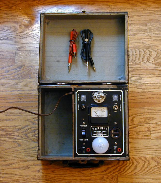
The $15 price was reasonable, so I picked it up. Here is a photo of my unit as found.
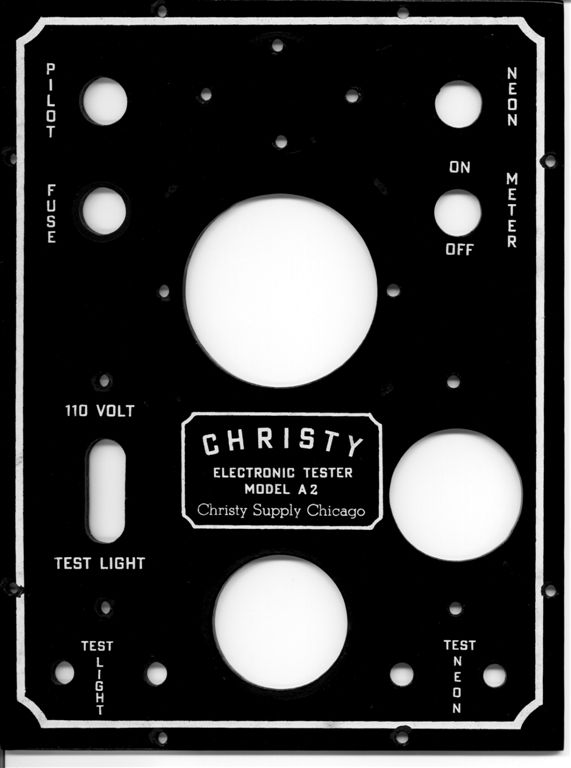
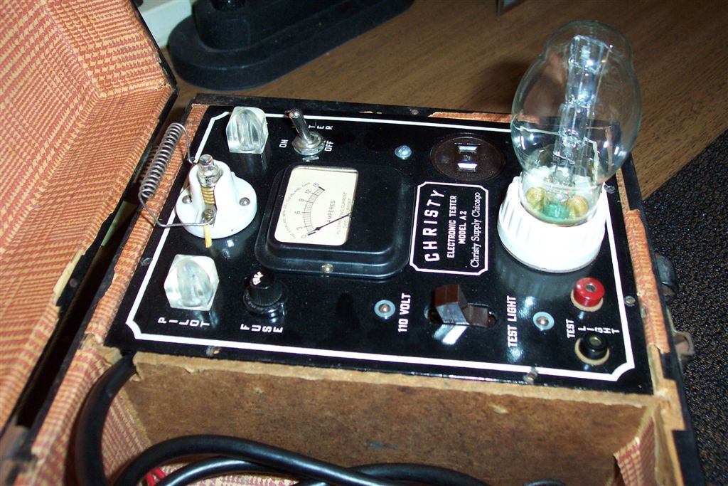
The next three photos show Gerry's unit after disassembly and restoration.
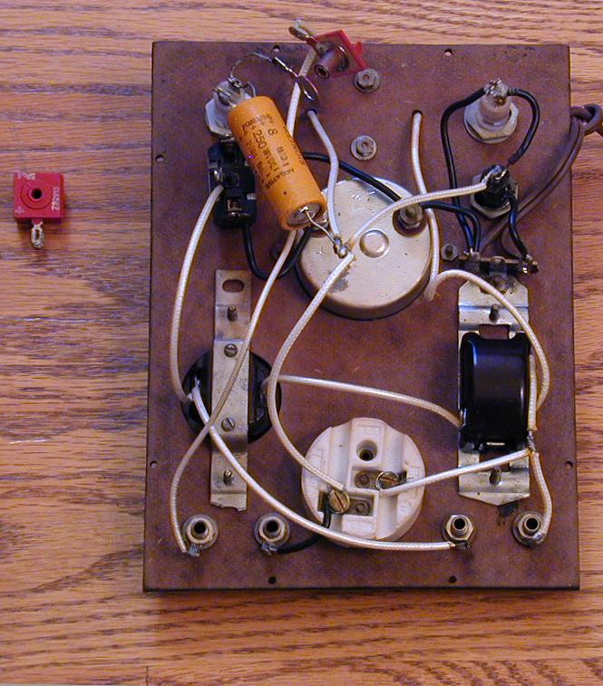
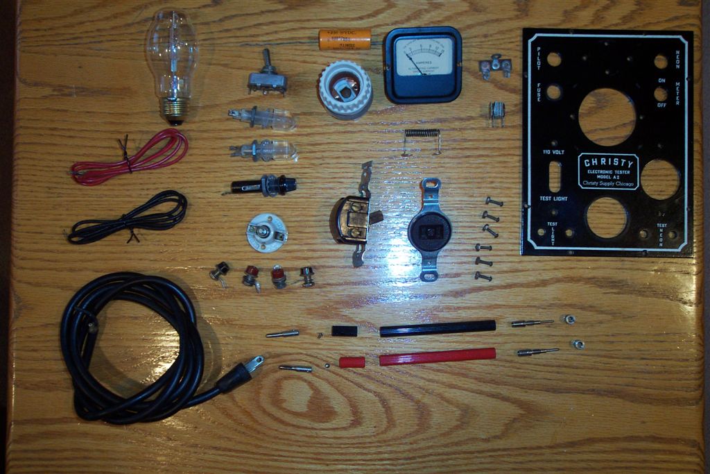
The next photo shows the innards of my tester. As you can see, it was a pretty simple kit to assemble.
The builder only needed to connect wires between the various controls and indicators shown on the
tester's front panel. Except, that is, for a small selenium rectifier and an 8-mfd electrolytic capacitor.
As you can see from the above photo, the little red rectifier fell apart at some moment during its service life,
and dropped all but one of its plates. I found them rattling around the bottom of the case when I opened it up.
In the storage compartment of the cabinet was an unused replacement rectifier, which you can see to the left
in this photo. I guess the previous owner
intended to repair the tester, but never got around to it.
Selenium rectifiers are unreliable, so I'll replace the old one with a modern silicon diode rather than take my
chances on the spare selenium unit, even though it appears unused. Inside the cabinet near the rectifier location
is a big black burned spot, indicating that it gave off a lot of heat when it failed!
A type 1N4005 diode costs about $1 and should be more than adequate.
The same goes for the electrolytic capacitor. Even if it hadn't been used all these years, the capacitor
probably has dried out and become unreliable, if it works at all. You can obtain an 8-mfd electrolytic
capacitor from Just Radios.
A 10-mfd capacitor will also work.
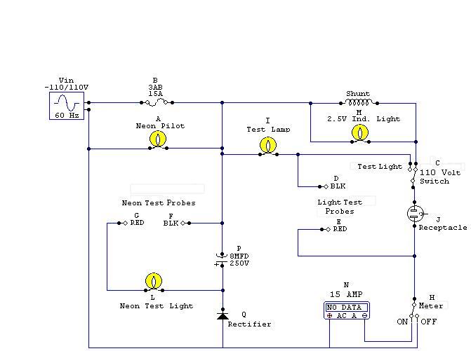
Gerry traced the circuit and created a schematic diagram for the Christy, for anyone who is curious. Click
on the image below to view the schematic.
This tester was apparently sold as a kit. If you find one, you might want to carefully check the connections
against the schematic, to ensure that everything was wired correctly and that the builder did not leave
any cold solder joints, etc.
Below are links to the Christy manual, which includes operating instructions as well as building
instructions. The final link contains a sketch with specifications for building a carrying
case just like the original, should you wish to do so.
Page 1
Page 2
Page 3
Page 4
Page 5
Page 6
Case
An advantage of this tester over my home-made dim-bulb unit is that it includes an ammeter to
show the power consumption of the unit under test. If you're an enterprising builder, you
could follow the schematic and manual instructions to make one of these for yourself. Or, if
you run across one at a flea market, this article may help you learn how to restore and use it.
Safety First
Like many vintage devices, including countless "All
American Five" AC/DC radios, the Christy was not built
to current safety standards. If you restore one, or build a replica,
use common sense and precautions.
A couple of years after I first wrote this article, I received the following
safety notes from Lee Whitehead.
I was looking for a Christy T-3 tester when I came across your
pages about a different model. The schematic shows a neon lamp
across a stiff voltage supply, which would blow the instant it
fires. I suspect the lampholder has a built-in current-limiting
resistor. If it is built in, then that should be noted, else a
beginner might try it exactly as shown, leading to disappointment,
not to mention smoke. The same thing could be said of lampholder A,
should the fuse open. BTW, those two lamp symbols should be changed
from incandescent to neon.


I also note that the test receptacle J is shown with an equipment
ground contact (highly unlikely if it's from the days of that line
voltage). It should be deleted for accuracy and it's never a good
idea to leave a three-prong outlet with no grounding conductor to
earth. Speaking of safety, you should have a prominent warning
that the probes of this device work directly off the line and
therefore any contact with them is dangerous and the equipment
under test may be energized with dangerous voltage, possibly
including the EUT chassis.


A good name for this thing is "the widow maker." In these days of
cheap DVMs, there's no excuse for using the probes at all. A box
with just receptacle J and its associated parts is less likely
to fry someone or startle into injury. It's fun to reminisce,
but who knows who might try to build it.
|