Midwest Model DD-18 (18-36) Console Radio (1936)


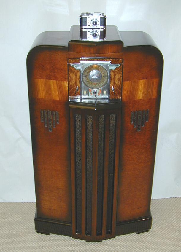
This large Midwest DD-18 console is a thrilling example of 1930s design. The dramatic coloring and wild chrome-plated dial make it a favorite of collectors. There are various definitions of what constitutes Art Deco, but this qualifies in my book. With its streamlined cabinet, geometric designs, and chrome ornamentation, it would have looked perfectly at home in a glamorous movie setting from the 1930s.
Description
The following photos show the Midwest after I finished restoring it. The outdoor photo gives a truer idea of the cabinet colors.
The cabinet face is finished with a burl veneer and the sides and front have a contrasting panel of tiger-stripe veneer. The bottom trim pieces, strong vertical grille, and rounded shoulders are colored with dark toning lacquer. The two small speaker openings on each side add a decorative touch, but do not contain separate speakers. As we'll see however, they include metal vanes that form part of the radio's speaker system.
This cabinet is super-sized, standing 48 inches tall, compared to an average of 41 or 42 inches for most consoles of the time. The extra height accentuates the bold vertical design of the cabinet front.
Below are the pages from the 1936 Midwest catalog for model DD-18. The two-letter prefix (AA, BB, and so on) identifies the cabinet and the number denotes the number of tubes. The 18-tube 1936 chassis is known as the 18-36. It was used in a few different cabinets that year, thus you have model numbers such as CC-18 and DD-18, but when looking for a schematic, you'll want to use the number 18-36.
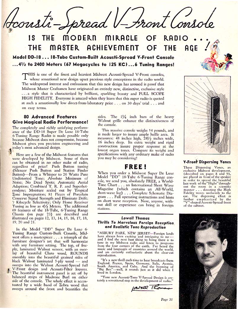
The rather breathless ad copy describes this as an "Acousti-Spread V-front console," referring to the V-shaped vertical grille bars. Metal "dispersing vanes" inside the speaker openings purport to spread the sound for better fidelity. The second page also includes an endorsement from Lowell Thomas, a leading broadcaster of the day.
Below is the back-cover Midwest ad from the January, 1936
issue of Short Wave Craft magazine. The price was $59.50 and the ad includes a testimonial
from Ginger Rogers.
Midwest sold its radios only through mail order, so catalogs and magazine advertisements such as this were the company's main marketing vehicle. We'll say more about the Midwest company in a later section.
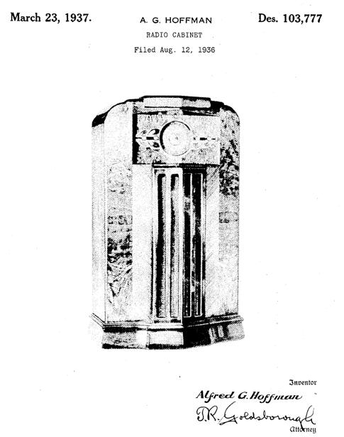
Here is the U.S. design patent (D103,777) for this cabinet. It shows a different dial style,
but it's clearly the DD-18 cabinet. Midwest also recorded the "Acousti-spread"
aspect of the speaker grille in design patent D96,750.
Dial and Controls
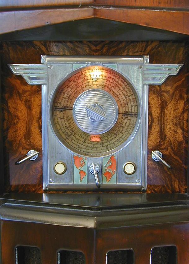
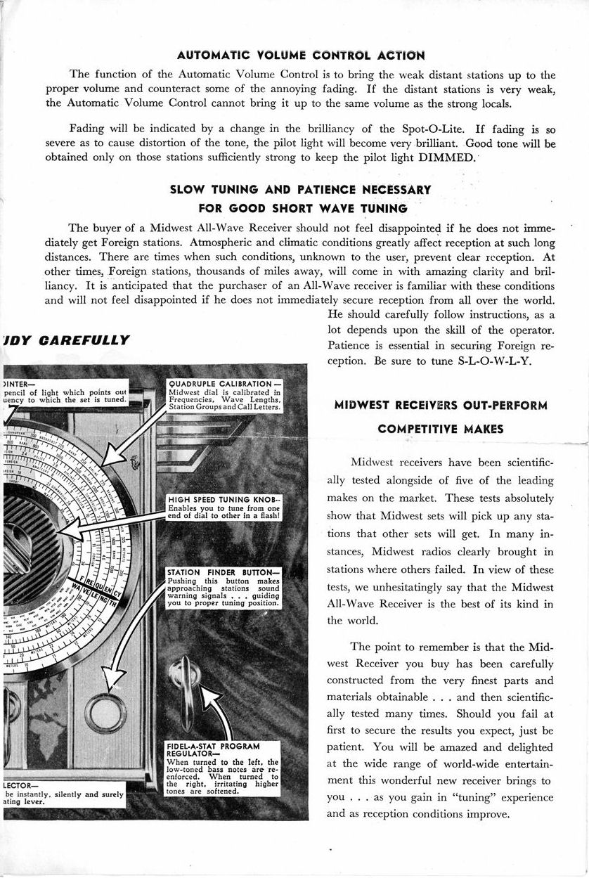
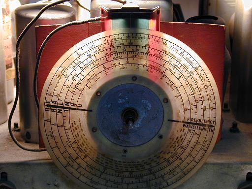
The centerpiece of this radio is its gorgeous dial, which combines bright plating, paint, and colored lights for a theatrical effect. Below are two views of the dial, illustrating the Midwest Tunalite tuning indicator.
In the left photo, the radio is tuned in to a strong station, in which case the pilot lamp behind the dial darkens. In the right photo, the radio is tuned to a no-signal spot between stations. The pilot lamp then brightens, making it easier to read a large portion of the dial. In the Restoration section below, we'll get a closer view of how this all works.
The above photos illustrate the two tuning knobs and five other controls. In the center of the dial are two chrome-plated knobs: a large main tuner, and a smaller vernier knob which makes it easier to zero in on shortwave stations.
The dial is airplane-like, with geometric "wings" on each side and strongly patterned rotating knobs in the center. Light green paint provides a contrast in the wings and center portions. Below the dial is a stylized map of the world, with the continents colored red, highlighting the radio's world-wide reception abilities.
Below the dial are three chrome paddle controls and two pushbuttons faced in mother-of-pearl. The leftmost paddle control is the power/volume switch. The center paddle is the bandswitch, and the right paddle is the tone control.
The left button is for "silent tuning." It cuts off the audio if you wish to eliminate all sound while tuning in a new station. The right button is the heterodyne, or "whistle," control. It is a fine tuning aid, useful for pulling in distant stations. When you hold this button down while tuning, the radio emits a high-frequency hiss or whistle. In the lower bands, the whistle control is a soft hiss that grows louder as you dial in the station. In higher, shortwave, bands, it's a high whistle that lowers in pitch to a growl or silence as you zero in. Like the Tunalite lamp, or a signal meter on a communications receiver, this does work, although I don't find it as useful as a conventional signal meter. In any case, Midwest chose to add a separate "heterodyne" tube, transformer, and associated circuitry to make this work.
The dial assembly is backed by a metal plate painted with a wood-grain pattern. If you refinish one of these radios, don't mistake that backing plate for wood and apply stripper. You will find yourself with a bare piece of steel!
Frequency Coverage
The Midwest DD-18 is a six-band radio, covering the standard broadcast band, the "low wave" band then used for aircraft and police communications, and four shortwave bands ranging as high as 60 megahertz. Although many consumer radios of the time included low-wave and shortwave bands, few radios other than communications receivers attempted to cover the highest bands used for ham transmissions.
The plastic dial scale is divided into two sections. The upper Frequency portion contains the familiar frequency markings. The bottom Wavelength portion portrays the same bands marked in meters, which are more often used in shortwave and ham broadcasting.
Midwest chose to label the six bands E-A-L-M-H-U. The E stands for European. In Europe to this day, "low wave" bands below our standard broadcast band are used for general broadcasting. In the U.S., these bands were formerly used for police and aircraft broadcasts; nowadays, they are largely silent. The A stands for American, I guess. In any case, it includes our standard broadcast band, from 550 to 1600 megahertz. The remaining bands are what we now call shortwave, L meaning low, M meaning medium, H meaning high, and U meaning ultra-high.
Midwest 18-36 Owner Manual and Service Manual
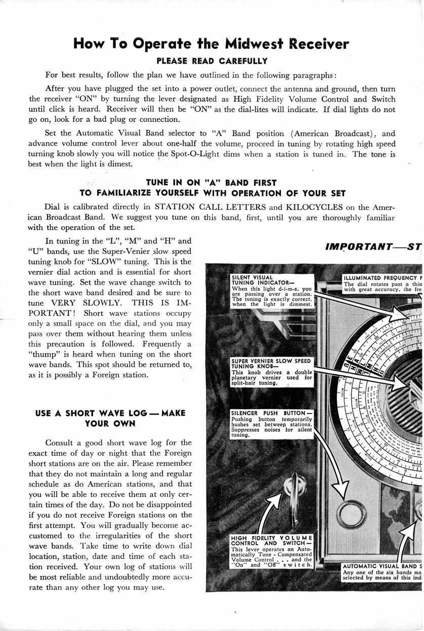
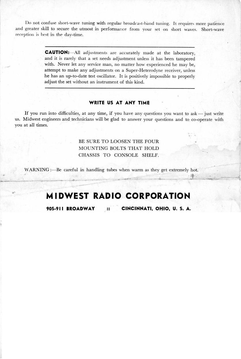
Below is the owner manual shipped with Midwest radios using the 18-36 chassis.
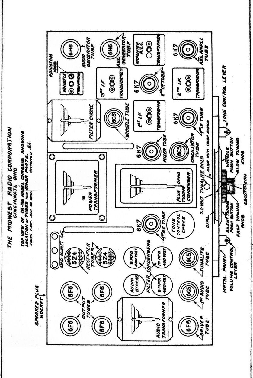
It includes operating instructions, a layout diagram, and schematic diagram.

Thanks to Robert Larsen for sharing this document. To print the manual pages,
first save each page to your computer (right-click on each thumbnail
image and choose Save Picture As...), and then print using a program
such as Photoshop or Microsoft Paint.
You can obtain the Rider's 18-36 service manual from this
page
at the Nostalgia Air website.
Chassis and Tubes
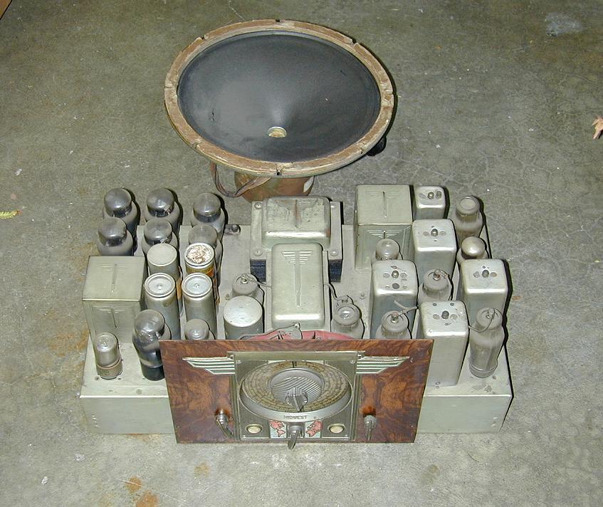
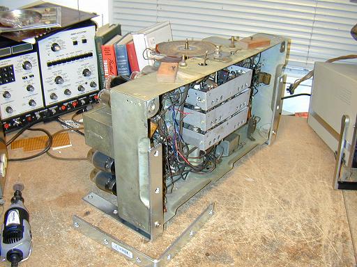
The next two photos show the massive 18-36 chassis from front and back. In these photos the dial backing plate and decorative bezel have been removed.

Midwest continued the decorative wings theme by stamping stylized designs into the cases of the transformers and the RF cage. These items, as well as the chassis, are plated with a shiny metal that I believe to be cadmium. Other things, such as the IF transformer cases and cylindrical electrolytic cans, are made of aluminum, which nevertheless shines up well if you have patience. The large 6K7 tubes in the RF and IF sections have two-piece metal "goat" type shields, which look pretty attractive, now that I have given them a coat of aluminum paint.
Here is a description of the radio's 18 tubes.
|
Tube |
Type |
Function |
|
V1 |
6K7 |
RF amplifier |
|
V2 |
6C5 |
Oscillator |
|
V3 |
6K7 |
1st detector |
|
V4 |
6K7 |
1st IF amplifier |
|
V5 |
6K7 |
2nd IF amplifier |
|
V6 |
6H6 |
2nd detector |
|
V7 |
6C5 |
1st audio amplifier |
|
V8 |
6F6 |
Audio driver |
|
V9 |
6F6 |
Audio output |
|
V10 |
6F6 |
Audio output |
|
V11 |
6F6 |
Audio output |
|
V12 |
6F6 |
Audio output |
|
V13 |
6K7 |
AVC amplifier |
|
V14 |
6H6 |
AVC Rectifier |
|
V15 |
6C5 |
Heterodyne oscillator |
|
V16 |
6C5 |
Tunalite |
|
V17 |
5Z4 |
Power rectifier |
|
V18 |
5Z4 |
Power rectifier |
In the 1930s and 1940s, radio manufacturers strove to equate the number of tubes with a radio's overall quality. In a general sense, that's true. The average 10-tube radio performs better than the average 5-tube radio. Like other manufacturers, however, Midwest chose to inflate its "tube count" by sometimes using two tubes where one would do. You could build this radio with one rectifier tube rather than two, for instance, or two audio output tubes rather than four.
In any case, the 18-36 works well as designed, with excellent sensitivity and audio performance, not to mention its extra features such as the Tunalite and heterodyne circuit. If I were designing a high-performance communications receiver with the same number of tubes, I might have added a second RF stage and skipped something like the heterodyne circuit, but it's hard to fault Midwest for their choices, given that they were targeting a consumer market.
The Midwest Company
With 18 tubes and a shiny plated chassis, the Midwest DD-18 is certainly impressive to look at. In that sense, it competed directly with expensive luxury radios such as E.H. Scott, and high-end models made by mainstream manufacturers such as Zenith and Philco.
Midwest took a different marketing approach, however. Its products were sold only through mail order, thus eliminating the expense of showrooms and salespeople. Relying on elaborate color catalogs and magazine advertisements, Midwest was a "direct marketer" of its time. That approach, combined with manufacturing economies, allowed Midwest to sell its radios for a fraction of the price of the major brands.
What were these economies? Well, the cabinet of my Midwest console is put together with nails and glue, not screws, and for such a large cabinet, the wood is rather thin. That being said, Midwest did not cheap out everywhere in the cabinet. The front panels are genuine burl veneer, something which other manufacturers occasionally replicated with cheap "photo finish," which is a paper decal printed with a colored grain pattern. The contrasting zebra-stripe panels on the front and sides are also real veneer.
In the chassis, the metal plating is rather thin and easily scratched. The sockets are the inexpensive wafer type rather than heavier (and more reliable) molded type. On the other hand, the coil forms are not cardboard, but ceramic, a costlier material usually found in communications receivers and luxury radios.
The Tunalite indicator also requires complicated mechanics and extra circuitry to achieve its unique effects. So it wouldn't be fair to call this a cheap radio, although at a price of $106.95, the DD-18 was much less expensive than radios with similar features.
To learn more about the company, visit Mike Simpson's
Midwest website. Mike is an expert in these radios, and he was generous with advice during this project. He also graciously provided images of the Midwest catalog pages for this model. (If anyone has a 1936 Midwest catalog for sale, please contact me by
email.)
Restoration
I purchased this console for $200 in December, 2003. The cabinet was in poor condition, having spent many years in an unheated, leaky storage building attached to a very large home in New Jersey.
Large areas of finish on the cabinet top had weathered away. The wood had cracked from moisture damage, and portions of the veneer had separated and even flaked off. The speaker grille cloth was in rags. The cabinet feet were loose, and one was missing.
The chassis was in much better shape. Everything was present and accounted for, only requiring cleanup and (I hoped!) routine electronic restoration. The speaker cone had a medium-sized tear, but otherwise was intact.
Cabinet Restoration
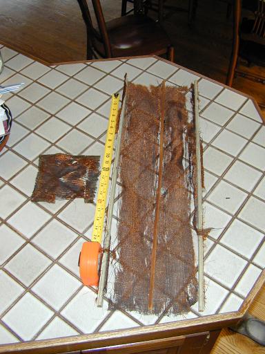
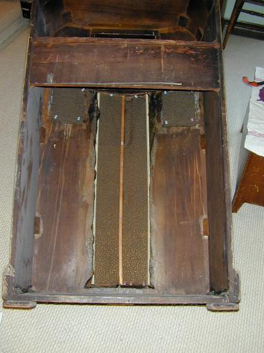
I prefer not to strip radio cabinets, but this one left me no choice. Before stripping, I had to remove the speaker board, grille cloths, and miniature sound vanes. The next photo shows the radio's speaker board with metal vane assembly.
I doubt that the metal dispersing vanes appreciably improve the radio's audio, but they probably can't hurt, either, and their inclusion allowed Midwest to make another marketing claim. Other radio makers of the time used gimmicky speaker schemes, including slanted sound boards (Philco) and enclosed speaker systems with internal channels (Stromberg-Carlson). In any case, small metal vanes similar to this are mounted behind the small openings in the cabinet face.
The chevron-like shape of the Acousti-spread grille requires that the grille cloth be fastened with thin wooden slats, in addition to glue. Here is old cloth after removal.
Stripping the Cabinet and Gluing Veneer
Stripping a large console is a laborious task. Here is the partly stripped cabinet.
I often use orange Citri-Strip stripper, but partway through the process, I found that it was simply taking too long, so I resorted to old-fashioned, heavy-duty stripper.
When you are stripping a cabinet, there will be nooks and crannies that tend to retain old color and stripping sludge. Wooden toothpicks can come in handy. An old toothbrush is also useful when cleaning those areas of used stripper. If you use a water-rinsable stripper, avoid soaking the cabinet too much; that can loosen the veneer.
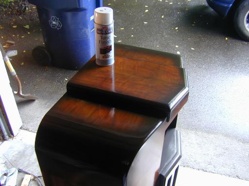
The next photo shows how I glued the bad veneer on top of the cabinet. Although I have a variety of woodworking clamps, none was able to reach from the back of the cabinet to clamp the glued areas near the front, so I used books and a full gas can as weights. I put waxed paper under the weights to avoid gluing them to the cabinet.
While we're at this photo, notice the strip of light-colored wood along the top of the beveled part of the cabinet top. Under the veneers on the top and front is cheaper wood of a different type. This practice was almost universal in radio manufacturing. It would be a mistake to use stain to re-color this cabinet after stripping, because the different kinds of base wood wouldn't accept stain equally, and you would end up with a peculiar, non-original color scheme. This part of the cabinet was colored with very dark toning lacquer at the factory, so that's what I'll use. The toner covers whatever is underneath, rather than soaking into the wood.
Sanding and Grain Filling
Stripping raises the grain of the wood, so you always need to sand it afterwards. Sanding also removes any leftover remnants of original finish or stripper residue. This process took a few hours, starting with lower grade paper (300 to 400) depending on the smoothness of the wood where I began, and finishing with very fine 600 paper.
After sanding, the cabinet felt uniformly smooth everywhere that I felt it. Your fingers are a more accurate indicator of smoothness than your eyes.
If you have stripped a cabinet down to bare wood, the next step is to apply grain filler. Wood has pores, just like your skin. If you skip this step, your finish will have that tell-tale "antique mall" appearance, with zillions of tiny holes and depressions that show the wood grain. You can't fill those holes by spraying on more and more lacquer. The depressions will remain even while the surrounding area is built up.
Grain filling is an art unto itself and I'm still not very good at it. Following the instructions on the can, I brushed liquid filler onto the cabinet one section at a time, waited what I thought was the right number of minutes, then briskly rubbed off the excess with rough burlap cloth. The idea is that the rough cloth will remove excess filler from the surface without lifting it out of the pores.
Simple in theory, but tricky in practice. In some cases, I ended up leaving too much sealer on the surface, requiring a re-sanding of that area. In others, I rubbed too hard (or was it too soon?), lifting filler from the pores and requiring a reapplication.
Eventually, the wood seemed to have a uniformly smooth surface. In any case, I was tired of this phase and began to apply lacquer.
In hindsight, I wish I had followed the advice of fellow restorer Bill Meacham, who says that he removes excess filler by scraping with an old credit card rather than rubbing with burlap. I'll try that method next time. Some folks also recommend spraying on a sealer coat of shellac before lacquering.
Lacquering
This phase of refinishing took a long, long time! Since the original finish appeared to have been glossy, I wanted to replicate that effect, even though I generally prefer a satin lacquer finish for radio cabinets. In achieving this, I got a lot of great advice from members of the rec.antiques.radio+phono newsgroup on USENET.
After spraying on a couple of base coats of clear lacquer, I gave the entire cabinet a coat or two of Van Dyke brown toning lacquer. This restored the original color to the lighter areas of the cabinet.
Some parts, however, had a contrasting darker color. These were the bottom trim pieces and vertical grille, the borders between the front and side panels, and around the cabinet shoulders and borders of the topmost trim piece.
I colored these areas by masking off the rest of the cabinet with tape and newspaper, then spraying on dark brown toning lacquer. Several coats were needed to get the color right.
When masking a cabinet, you can use light painter's plastic, a couple of thicknesses of newspaper, or anything else that won't let the lacquer soak through. I use green or blue colored painter's masking tape, which doesn't adhere as strongly as light tan masking tape. Don't stick the tape on too hard. I remove the mask as soon as each coat has dried. Pull it off very slowly, and horizontal with the surface, rather than at a 90-degree angle. If you stick the tape on too strongly, leave it on too long, or rip it off too fiercely, you may tear away the underlying finish.
Once the color looked correct, I applied many coats of clear lacquer to get a deep, lustrous finish. Between each clear coat, I gave the new coat a light sanding with very fine paper and then a careful cleaning with a tack rag. As I built up successive layers of clear lacquer, I went to finer and finer paper grades: 800, 1000, 1500, and finally 2000. You can find this extremely fine paper in the body shop section of many auto part stores. If you own spray equipment and you're a better spray-meister than I am, you may not need to use such fine grades of paper.
A useful tip for such fine sanding is to lubricate your paper. The lubricant carries particles away from your paper and prevents it from clogging. I found that paint thinner (mineral spirits) worked very well, although some people use water with a drop or two of soap.
Eventually, the cabinet began to shape up. Compare this view with an earlier photo.
Fighting Lacquer Blush
I don't own spray equipment, so the entire cabinet was done using Mohawk brand spray cans. Since I have to spray outdoors, and live in a humid climate, lacquer "blush" was an occasional problem. Blush occurs when you spray in high humidity and moisture is trapped underneath the fresh lacquer, giving it a whitish appearance.
A mild case of blush will sometimes cure itself if you wait a few hours or days. Bad cases will never go away, and that's what happened when I was applying one of the many lacquer coats to the top and shoulders of this cabinet. The beautiful dark finish that I had worked hours to achieve was now spoiled by whitish areas under the new lacquer.
As I learned from the r.a.r+p group, there are various ways to combat blush. One is to leave the freshly lacquered cabinet out in the sun for a while. Another method is to gently warm the fresh lacquer with a lamp. In both cases, the heat helps the moisture to dissipate. It also helps to apply a few light coats of lacquer, rather than hose the cabinet with a single heavy coat.
If you leave your cabinet out in the sun, don't let it overheat. On two different occasions, I left it in the sun too long and the lacquer finish developed a bunch of little bubbles. When I tried to sand those bubbles smooth, the upper part disappeared completely, revealing that the bubble had lifted up the underlying lacquer, all the way down to bare wood!
Repairing these bubble disasters required several more rounds of re-toning and re-lacquering, with careful sanding in between each fresh coat. To level out the holes, I dipped a toothpick or fine artist's brush in brushing lacquer and dropped little blobs into each hole. Eventually, the blemishes disappeared.
The refinisher's secret weapon against blush is "blush eraser," a combination of lacquer thinner and retardant which dissolves the upper coats of lacquer and allows the moisture to escape. After suffering through the sun-bubble disasters, I got a spray can of Behlen brand blush eraser and it worked like a dream.
In the final phases of refinishing, our September weather turned cool and rainy. On those days, I gave the garage door a lot of exercise. For each new coat of lacquer, I would open the door and quickly trundle the cabinet out under the roof overhang, then spray on the next coat. Then I would trundle the cabinet back into the heated garage, close the door, and wand a flood lamp slowly back and forth over the fresh lacquer, warming it just enough to prevent blush. This method was tedious, but effective.
Achieving the Final Gloss
I don't advocate using a high-gloss finish on most radios. This set is special, however. It's a real looker, one that I intend to keep as a highlight of my collection. The dramatic styling also lends itself to glossy, rather than satin, finish.
When I asked r.a.r+p what to do at this point, I got a variety of answers, not always in agreement. Some folks advocated putting on a coat of high-grade wax. Others described how to use rottenstone, the French Polish technique, or even very fine rubbing compounds. In the end, I used what was available: Novus Plastic Polish #2, a compound that I have used to polish many Bakelite and plastic radios. I didn't use it on the entire radio, however, only on the parts of the top and front near the dial, where a little extra gloss might be appreciated. The rest of the cabinet is exactly as it was left after spraying on the final gloss coat and rubbing it with a soft cloth.
Replacing Grille Cloth and Speaker Vanes
Having completed the cabinet finish, I gladly turned to other tasks. The original grille cloth was unsalvageable, and I had been advised that you can get a good replacement pattern from John Okolowicz at Antique Radio Grille Cloth, so I ordered a swatch of his #31 "whiskey rayon" cloth and installed it.
This cabinet requires three pieces of grille cloth: a large
rectangle for the center grille and two small squares for the side openings. Ironing the cloth with spray starch will stiffen it and help to avoid wrinkles. I used household glue to fasten the cloth to the cabinet and pushpins to hold it in place while the glue dried. This cabinet also uses thin wooden strips to secure the fabric inside the V-front grille.
The metal speaker vanes were corroded, so I cleaned them and gave them a coat of black lacquer before screwing them back into the cabinet. Be careful when inserting screws through grille cloth. It's best to poke a starting hole first with an awl. Then it's less likely that the screw will catch the cloth and twist it.
After all that work, the cabinet was ready to accept the restored chassis. In case you are wondering, I didn't do all of the cabinet work before starting the electronic work. I alternated between the two, but it makes more sense to describe them separately.
Electronic Restoration
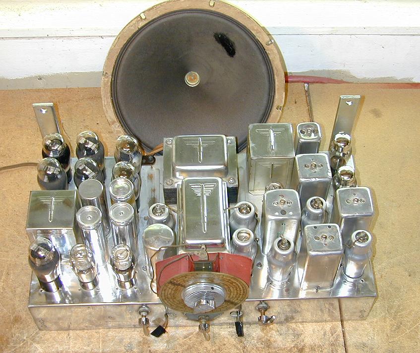
The next two photos show the 18-tube chassis before and after restoration.
Looks about the same, you might say, except for a little polishing up, but this was a major restoration project.
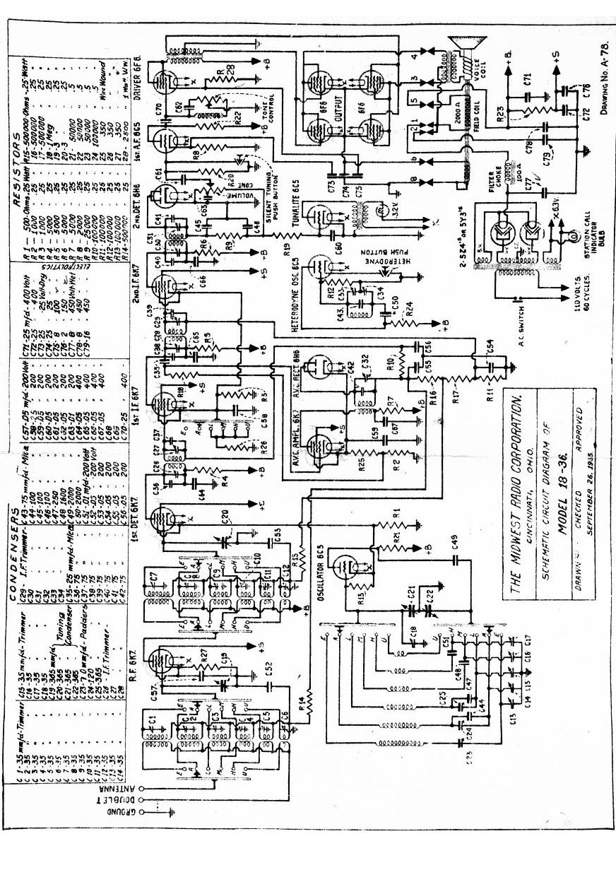
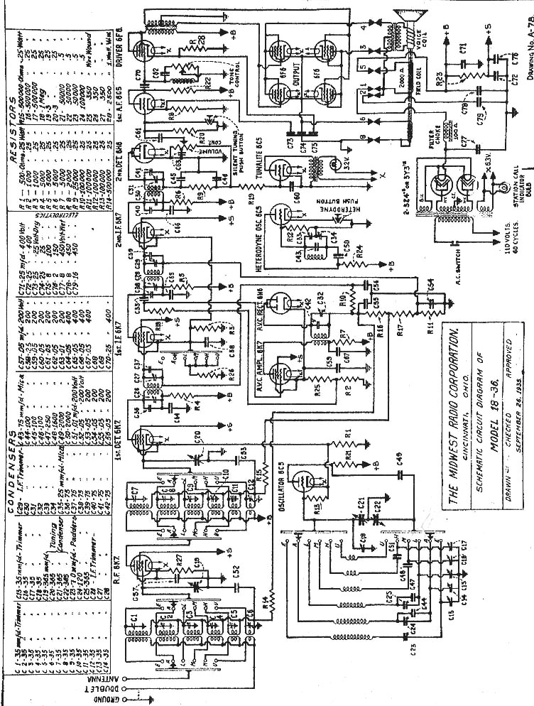
You can view the 18-36 schematic and parts list by clicking the image below. It has been sized to print on a single 8.5 x 11 sheet of paper if you print in portrait mode. You will get better results if you save this image and print it from a paint program such as Photoshop rather than from your web browser. To save it in Windows, right-click the mouse anywhere on the full-size image, then choose Save Picture As . . .
Dial and Controls
The dial and controls were in good shape, needing only cleaning and polish. The painted backing plate had been covered with a sloppy coat of hand-brushed lacquer or shellac, making it look rough. I removed that and applied a couple of coats of clear lacquer, to improve the appearance.

In the next photo, the knobs, dial bezel, and backing plate have been removed. If you look at the upper right corner of the plated bezel, you can see that a little preliminary cleaning and polishing removed quite a bit of grime. Be careful when polishing this bezel. The plating will not stand up to harsh abrasives.

You must unsolder the leads to the two pushbutton switches in order to remove the bezel and backing plate. It's not absolutely necessary to remove all this stuff, if the switches still work and you're satisfied to polish the bezel and backing plate in place.
The following close-up of the dial gives an idea how the Tunalite tuning indicator works. I would recommend that you not remove this assembly unless necessary. You can lubricate everything, and replace the pilot lamps if needed, without disturbing the original registration of the dial on the tuning shaft. Fiddling with these gizmos might also cause the upper and lower lamps to illuminate the wrong areas when you change bands.

The dial scale is made of plastic with printed markings. Since the radio has no dial cover, it's normal for the scale to show some wear. This one was quite presentable, so I gave it a careful cleanup with distilled water and a soft baby diaper. Use caution when cleaning old dial scales. Some of them (not this one, however) use fragile water-based paint that will wipe off at a touch. When in doubt, test your cleaning materials on a part of the dial that won't show when the radio is reassembled.
In the above photo, you can see part of the Tunalite mechanism. The 3.2-volt pilot lamp is mounted behind a red-and-green colored plastic shade, in front of a red cardboard backing. This assembly is connected to the bandswitch shaft with a rack and pinion gear. When you move the bandswitch, the whole apparatus moves up or down, so this pilot lamp illuminates the chosen band in the top, or Frequency, part of the dial.
The bottom, or Wavelength, portion of the dial is illuminated by a second, stationary, pilot lamp, which shines through a hole in the chassis. A rotating metal mask between the lamp and the dial illuminates succeeding portions of the dial as you move up the frequency bands. This photo gives an idea how both dial lamps work in practice.
The tuning knobs and paddle control knobs are chrome plated and quite robust. They attach to their shafts with hex screws. The vernier tuning mechanism on my DD-18 was inoperative when I purchased the radio. With the chassis lying on its back, I carefully introduced some WD-40 solvent down the shaft and let it work for a while. Then I re-lubricated the shafts with light oil, and both tuners worked just fine.
Cleaning and polishing the chassis took hours. The next photo shows what a difference a little polish can make.

The plating on the transformer cases, RF cage, and chassis looks like cadmium to me. It is soft, easily scratched, and rather thin. Cadmium is a poisonous metal, so if this is indeed a cadmium-plated chassis, use precautions while polishing. Wear rubber gloves if you hand-polish, as I did. Since the plating is so soft, I would avoid using harsh measures such as steel wool or a power tool to buff it up. I used metal polish and a soft cloth.
A Cheap and Simple Chassis Holder
While working on this chassis, I often needed to turn it on its back or side. With smaller radios, it's usually not hard to turn the chassis on the workbench and find something to prop it up and keep it stable. Not so with this large, top-heavy chassis. My solution was to buy four sturdy metal "L" braces. Screwed into the mounting holes on the bottom of the chassis, they allowed me to flip the chassis any direction that I wanted, without risking falls or damage to connections on the chassis front or back. In this view, only two braces are in use.

In the photo above, I have fixed braces to the back mounting holes on the chassis, allowing me to securely set it on its back. At other times, as you'll see later, I attached braces to the front of the chassis, or moved them to the sides, as needed, making it possible to turn the chassis in any direction and work securely on the bench without fear of tipping. During most phases of the project, I had braces attached to all four mounting points, which allows one to turn the chassis completely upside down, as long as you turn the bandswitch to higher shortwave bands so that the Tunalite shade doesn't project far enough to hit your workbench.
Replacing Capacitors
Like most old tube radios, this one had a number of old electrolytic and paper capacitors that needed replacing. You can read about this general process in
Replacing Capacitors in Old Radios.
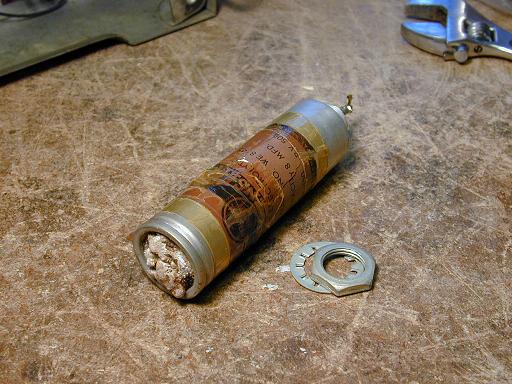
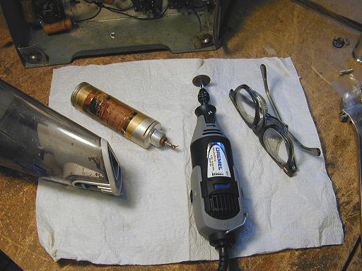
I don't always take such pains, but in this case I spent the extra time to "restuff" the original electrolytic capacitors, which are mounted in aluminum cylinders above the chassis. The following photos illustrate the process, which basically amounts to cutting open the old can, removing its innards, replacing them with one or more new capacitors, and sealing the can back up with epoxy.


Incidentally, the stuff on top of the old can that looks like bird poop is dried residue from inside the can. This capacitor was a "wet" type that used a weak boric acid solution as its electrolyte. Over time, the solution invariably evaporates, often leaving residue like this on the top of the can, where there are vent holes, or on the bottom, where it may have leaked past a gasket. Don't be scared of this stuff. It can easily be scraped off and washed away with water.
In the next photo, two of the four electrolytic cans have been removed for restuffing, and I have taken that opportunity to clean and polish that area of the chassis.

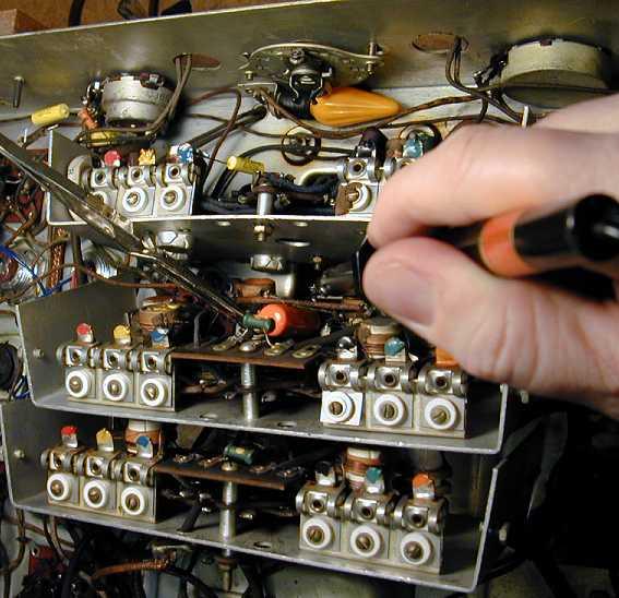
There are three small paper capacitors inside the RF, Mixer, and Oscillator cages under the chassis. After you remove the cage covers, you can see them. In the following photo, one near the top has already been replaced with a tiny yellow substitute. The other two are marked with red arrows.

To reach these buried capacitors, you need to remove the bandswitch shaft, shown running vertically in the previous photo, and remove the cage mounting screws from above the chassis. This allows you to gently nudge the cages far enough apart to reach in with a thin soldering iron.
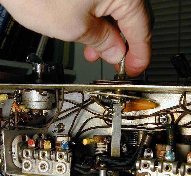
The flat bandshaft is held onto the bandswitch with a tight spring clip. I wasn't able to free it from the clip until I loosened the bandswitch mounting outside the chassis and rocked the assembly to one side, as shown below. Once that's done, you can draw out the bandshaft from below. Note: While the bandshaft is out, be careful not to move the bandswitch connection or the switch wafers, which could disturb the tuning and goof up a lot of circuit connections.

After the cages were loose, there was barely enough room to squeeze in my thinnest tools and replace the paper capacitors with new "orange drops." Needless to say, you want to be careful working in these tight quarters. There are coils with hair-thin wires, small trimmer capacitors, and other things that you don't want to break or fry.

This radio also has a few paper capacitors hidden inside the aluminum cans holding the IF transformers and AVC transformer. These capacitors have a flat, rectangular plastic case, rather than a cardboard cylinder, so that they can fit into the meager space under the transformer plate. The next two photos show one of the suspect capacitors, and the way in which I loosened a transformer can enough to replace it.


Although its flat case resembles that of a (usually) reliable mica capacitor, this one is actually the unreliable paper type. Look at the value: .01 mfd, larger than what you would find for micas, which always have smaller values. This is a "micamold" type paper capacitor, made infamous by the Micamold company. Despite the name, it contains paper, not mica. And these caps are not always made by Micamold. This one was manufactured by the Solar company.
Looking back at the previous photo, if you remove the mounting nuts at top and bottom of the transformer can, there may be enough slack in the connecting wires to let you replace the hidden capacitor without unsoldering and reconnecting all of the transformer leads. Keep your leads short and solder carefully. You don't want to inadvertently mount the new capacitor so that its lead shorts out to the chassis after you screw the can back down.
One of these cans also contains a 1-megohm resistor. In my experience, resistors of 1 megohm and higher frequently drift so far out of tolerance (usually higher) that they should be replaced. In this case, the 1-meg resistor had changed more than 200% in value! As long as you have the can open, you should at least check the resistor's value.
Later in the restoration, I needed to remove the can completely and check the values of small mica capacitors mounted high up in the transformer assembly. If you need to do that, unsolder the metal caps that go from the transformer leads to the grid terminals of the nearby 6K7 tubes. The unsoldered cap should slide right off the connecting wire. Resoldering those caps afterwards is a simpler business than cutting the grid lead to remove the can, then replacing the lead later on.
Aligning the Receiver
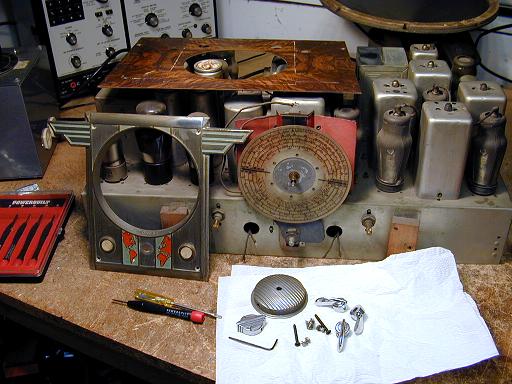
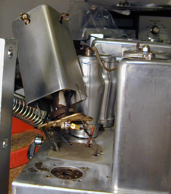
Next, I aligned the receiver for the first time. The next photo shows the basic setup.
Here, I have attached the L braces so that I can securely stand the chassis on end. Alignment requires access both above and below the chassis. The transformer adjusters are on the top of the cans, while the trimmer and padder adjusters are underneath, reached through little holes in the RF, Oscillator, and Mixer cage covers.
Next to the radio chassis is an analog multimeter, used to measure the receiver's output during alignment. The grey instrument is my trusty old EICO 324 signal generator. The small black radio under the signal generator is a Grundig Yacht Boy 400.
Because it has a digital readout, I use the YB400 to make sure the signal generator is set to the right frequency. (The EICO is stable enough for this work, but its dial is not very accurate.) If the radio doesn't receive the needed frequency, you can use a multiple (i.e., harmonic). For instance, to set the generator to 456 kHz, I set the radio to receive at 912 kHz, twice that frequency, and listen for the generated tone as I move the generator's dial.
Shakedown Cruise
After the alignment was finished, the radio seemed to work well on all bands, with good sensitivity and audio. The Tunalite worked fine, as well. I played the radio on the workbench for a couple of hours and congratulated myself on an easy restoration.
When I turned the radio back on the next day, a couple of problems emerged. For starters, there was no audio output! My first reaction was to gently push and wiggle each of the audio tubes in turn. Pushing the 6F6 driver tube produced explosive static sounds and intermittent audio. Clearly, the tube pins and socket needed further cleaning.
Although I had previously cleaned them, I took this opportunity to repeat the cleaning regime for all 18 tubes and sockets. Every pin of every tube was lightly rubbed with very fine sandpaper. Then I sprayed a little DeOxit cleaner into the socket and inserted and re-inserted the tube several times, until I could feel the pins grabbing.
After this treatment, the audio returned, and I gave the radio another shakedown cruise of a couple of hours. Again, everything seemed fine.
Intermittent Tunalite and AVC Problems
When I tried the radio on the following day, another puzzling symptom appeared. The Tunalite seemed to be inactive. Instead of dimming when you tuned in a station, the upper pilot lamp remained bright at all times.
I hadn't paid much attention to the Tunalite circuit up to that point, but it seemed like an obvious place to start. I replaced a couple of previously-overlooked 3-megohm resistors, but that didn't improve the Tunalite response. When I queried the rec.antiques.radio+phono newsgroup, Jeffrey Angus provided this useful analysis of how the Tunalite circuit works.
Phil Nelson wrote:
> I have already recapped the radio and replaced R19 and R20 (both 3 meg). All
> tubes test fine, needless to say. Perhaps I don't completely grok the
> Tunalite circuit, but it appears to take grid voltage for the 6C5
> Tunalite tube via one leg of the volume control and the transformer
> feeding signal to the 2nd detector.

Yes, the audio is derived off of the bottom of the last IF
transformer. (Between the 6K7 and 6H6 tubes) It goes through
a low pass filter, C45, R9 & C44 to the volume control and R19.
Note: This low pass filter is to get rid of any 455 kHz ripple
on the detected audio.

From R19, it gets a little strange. ;-)

They are using the filament voltage, to feed a small
transformer, and then progressively shorting the output
of it with the 6C5 "tunalite" amplifier.

From what I can discern, R19 and C60 form another low pass filter.
Probably set below normal audio rates. This feeds the average
detected audio level to the grid of the 6C5 tube.

In essence, you have a triode with AC on the plate, and the
control voltage causes a varying load on the transformer.

The more signal you have, the more negative the voltage at the
grid of the 6C5 is. As a result, it conducts less, and the higher
an impedance it looks like. This makes the bulb get dim.

If the grid voltage goes near to zero, the triode will conduct,
rectifying the filament voltage and making the transformer
reflect a lower impedance in series with the tuning lamp,
causing it to get brighter.

Definitely a different method for a tuning indicator.

Jeff
This began a long period of debugging and testing. Irritatingly, the problem seemed to come and go. Since it had appeared after I had done the first alignment, I wondered whether a flaky trimmer capacitor in an IF transformer might be the cause. Mike Simpson also suggested checking the small mica capacitors in those transformers.
This meant opening up the IF and AVC transformer cans. Each of the trimmers was cleaned and exercised. The little 75pf mica capacitors were replaced. (Not all of them were bad, but it's about the same amount of work to replace one as it is to disconnect one leg, test it, and reconnect it if it's good.) I also replaced a 1-megohm resistor that I had previously overlooked.
Cleaning the trimmers meant that their adjustment had been lost, so I did another complete alignment. All of the trimmers worked smoothly and peaked nicely on the meter, so I crossed them off the list of potential troublemakers.
After all that labor, the radio worked fine . . . for a while. During the next bench test, I was listening when, in front of my eyes, the signal suddenly faded lower and the Tunalite indicator brightened to its low-signal point.
Hmmm . . . perhaps the problem was caused by low gain somewhere earlier in the signal path, not by a Tunalite defect per se. This occasioned a long round of testing voltages, etc., in the RF and IF stages, as well as the AVC circuit, since the AVC circuit controls the gain in those stages.
I didn't find any obvious problems, which was reassuring in the sense that many components were working correctly, yet troubling because the problem still came and went unpredictably.
Intermittent problems can be extremely hard to solve. They can be caused by anything from a dirty switch contact or tube pin, to a broken or "cold" solder joint, which connects at some times and not at others. They can even result from a little stray blob of solder that becomes lodged between two connections.
I went through all of the circuitry for the RF, IF, AVC, and Tunalite, carefully prodding components and wires with the eraser end of a pencil and listening for any change in the receiver. I also re-cleaned the multi-stage bandswitch, spraying its contacts with DeOxit and working it back and forth through all bands a number of times.
Tube sockets also get extra attention. The wafer sockets used in this radio are prone to bad connections. A molded type socket has cylindrical contacts into which each tube pin slips. A wafer socket, on the other hand, has a set of four toothed tangs which grab the pin. As long as the springy tangs are bent inward sufficiently, they make good contact with the pin. Over time, however, their grip tends to relax. The open construction also invites corrosion and dirt buildup over time.
To cross sockets off my list, I gave them a thorough cleaning and touchup. For every hole in every socket, I ran a round needle file through the hole to eliminate all corrosion and dirt inside the tangs. Then, from the underside of the chassis, I carefully squeezed the tangs together to guarantee a secure connection to the pin. With 18 tubes, and 8 pins per tube, this meant repeating the procedure 144 times!
I also found several resistors in the AVC circuit that had drifted far out of tolerance, which could affect the gain. After replacing them, I measured reasonable voltages in the main AVC line, ranging from negative (-) 10 volts when tuned into a strong local station, to around 0 volts when tuned to no signal.
Following the next bench test, the radio seemed to be performing normally. Just to make sure, I played it off and on for a few hours at a stretch. At long last, I had conquered the Tunalite demon and the radio was ready to use.
So, what was the answer? I think there wasn't a single answer to this puzzle. Instead, there were a number of little causes, such as dirty contacts, drifting resistors, cruddy trimmers, out-of-tolerance micas, which together prevented the radio from reaching peak performance.
In any case, since the radio was working normally, I finished by giving it yet another alignment, in case replacement of components in the RF and following stages had set things a bit off.
I call this sort of restoration "death by a thousand cuts." A simpler, or newer, radio won't normally need such thorough treatment.
The newsgroup discussions of the AVC and Tunalite problems were interesting, but too long to include in their entirety. Here are links that you can follow, in case you're interested:
Tunalite
Discussion ,
AVC
Discussion.
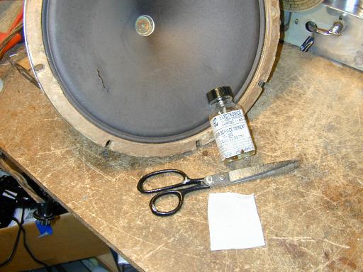
Repairing the Speaker Cone
Tears and small holes in a speaker cone are easy to fix. I cut a piece of paper from a tea bag and used that to reinforce the glue repair. You can use flexible fabric glue, although I use a special glue called service cement, specially designed for speaker repair.

After that photo was taken, I trimmed the piece of tea bag paper to shape before gluing it into place. For smaller tears, you can dispense with the paper reinforcement and simply hold the edges together with your fingers until the glue dries.
Fixing a Broken Tube Grid Cap
While I was working on the electronics, one of the grid caps on a 6K7 tube popped loose. It's possible, in fact, that this grid cap had been loose for a while, contributing to the intermittent gain problems. In any case, I learned from the r.a.r+p group that you can repair the cap rather than throw away the tube.
When the cap comes off, you'll see a wire protruding from the glass top of the tube. If you're lucky, this wire is still long enough to reach the top of the cap, as it did originally. The cap was soldered onto that wire, so your first task is to heat the cap and remove the old solder, exposing the hole. I also gently scraped the wire and "retinned" it with a small amount of solder.
Then you can apply clear epoxy to the underside of the cap and glue it back onto the tube, making sure that the wire comes up through the hole. (If it's too short, you'll need to splice on a tiny bit more wire before gluing the cap.) After the glue dries, you can resolder the connection at the top of the cap. The next photo shows the tube after a successful repair.
Final Thoughts
Restoring this handsome console took a lot of labor, and considerable advice from others, but the results were definitely worth it. It's a centerpiece of my collection, and it has been placed where visitors can see it as soon as they enter our front door.
A project this big can tire you out, however. After finishing this one, I decided to take a vacation from consoles and work on smaller radios for a while!
|