RCA Model WV-97A Senior VoltOhmyst Meter (1953)


This RCA model WV-97A is a typical 1950s service-grade meter for measuring
resistance and AC/DC voltage. Service grade means that it's accurate enough
for everyday radio/TV repair work but not suited to a laboratory.
Old test instruments like this are easy to find and usually inexpensive.
I don't really need another tester, but it would be fun to use a vintage
meter occasionally while restoring old radios and TVs. Like every
1950s tube device, it will need routine reconditioning, of course.
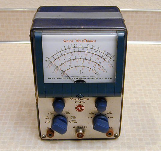
The front view shows its simple controls and large, easy to read dial.
The two round knobs let you adjust the needle to zero before making a measurement.
In some cases, it's also useful to set it in the middle of the dial, to
watch the needle swing back and forth between positive and negative values.
The lower left knob selects measurement ranges for both voltage and resistance.
The lower right knob turns on the power and selects the meter's functions: negative
DC voltage, positive DC voltage, AC voltage, and resistance.
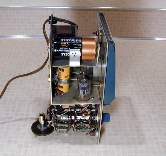
From the left side, we see the internal battery and one 12AU7 tube.
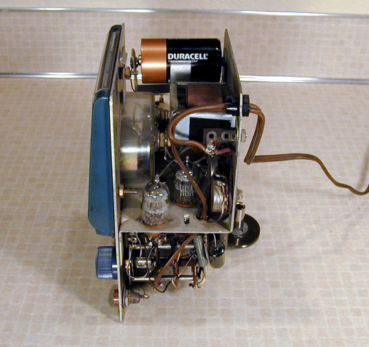
On the right, we see two 6AL5 tubes.
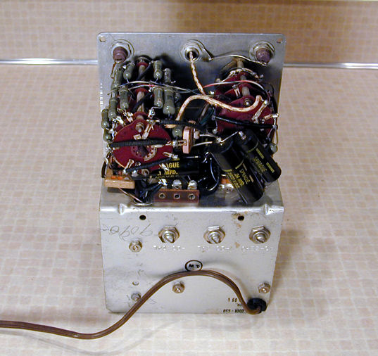
A rear view shows the range selector, with banks of high-accuracy resistors
that are switched in and out of circuit for different ranges. The function
selector connects the components used for each kind of test.
My WV-97A came without its original probes. For the time being, I am
using other probes from a modern meter.
This instrument has been serviced before. A previous owner replaced
its original paper capacitors with black molded paper caps.
Notice how two of these "black beauties"
are connected in parallel. Here, the schematic calls for a
.047-mfd capacitor rated for 1000 volts. Lacking the correct part,
the serviceman piggybacked together one .04-mfd and one .007-mfd cap, each with
a 1600-volt rating. As you can learn in my
capacitor replacement article, connecting
caps in parallel combines their capacitance value. If the voltage
ratings are equal, that's the resulting voltage rating. If one is lower,
the combined cap has that lower rating.
Black beauties are bad news no matter when they were installed, since they
dry out with age whether or not they're used. I'll replace the piggybacked pair with one .047 cap rated for 1000 volts, as specified.
In the previous photo, you can see the ends of a second piggybacked pair,
stuffed deeper inside the chassis. It was quite a trial to replace those.
Another routine step is to clean all of the switch contacts and potentiometers with DeOxit.
Accuracy is the goal and we can't allow any intermittent or funky connections.
I also tested the resistance and range of this unit's zero-adjust potentiometers,
using a newer multimeter.
Following rehab, I tried out my VoltOhmyst, with mixed results. The voltage
functions worked fine, but the resistance function did not.
The WV-97A manual tells you to check the battery if the resistance function is
faulty. Since I had just installed a fresh battery, that cause was easily ruled out.
However, following the advice of a fellow restorer, I carefully checked the battery
wiring and found a broken lead.
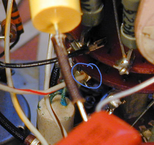
The broken lead is circled in blue. Although it appears to be connected,
it is simply resting on the terminal without making electrical contact.
Who knows, perhaps I knocked the connection loose when straining to reach
the innermost ends of those buried capacitors.
The resistance function worked after I resoldered that connection,
but the meter was far from accurate. If you look
back at the previous photo, you'll see a white cylindrical resistor with
dual leads that are turning green with corrosion. This is part of the
network of resistors mounted on the range switch. Different resistors
are selected when you choose different measurement ranges.
The white resistor has no markings and it's a different type than the green
"dogbone" type wirewound resistors used everywhere else in the
range switch. I suppose it's another replacement by the same repairman.
It measures at slightly over 20 ohms,
more than twice the specified value of 9.75 ohms.
Don't ask me why the previous owner replaced a 1% precision resistor
with one so far off the right value, since there's no hope of the meter
working correctly in this state.
Reaching that resistor will mean disconnecting several leads and
removing the range switch completely. After I install the
right part, I'll try to recalibrate the meter according to the factory
manual.
|