|

Rebuilding the Hallicrafters SX-28 Gearbox
By Doug Moore KB9TMY


Anyone who has labored through the restoration of a Hallicrafters SX-28 or SX-28A communications receiver knows that this fine old band cruiser is somewhat of a challenge to properly restore. Fortunately, thanks to the Internet, we have today at our fingertips the knowledge of those that have traveled this road before, and documented their journey. The restoration of my first SX-28 was greatly aided by the information found on the web by A.B. Bonds, Phil Nelson and Jim's SX-28 page. A.B. Bonds pioneered the techniques for rebuilding the RF sections, and Phil Nelson showed us how to restore the front panel, as well as providing an excellent photo pictorial of the entire restoration process.
With all this data available, and having already successfully restored one SX-28, you would think that a second one would offer no challenges. But, when I began the restoration of the second receiver, I discovered that the old Hallicrafters SX-28 still had a lot of secrets that no one had yet revealed.
My second SX-28 was found in a damp garage, where it had been stored and ignored for many years. All the metal parts showed ample rust and corrosion, and generally it looked pretty hopeless. Only true love could inspire someone to tackle this kind of project. When I finally got the monster out of its case and on the workbench, things looked even bleaker. All the shafts on the tuning mechanism were rusted solid and several of the potentiometers on the panel as well. Since the front panel had to be removed anyway, I decided early to pull out the tuning mechanism and see what needed to be done. If I couldn't restore the tuning mechanism, this radio would probably end up as a parts donor.
The remainder of this article describes what I found, and how I solved the various problems I encountered. It should be noted that the procedure I developed is not for the faint of heart, but I personally feel it is worth it. I do not claim that this is the only method that will work, only that this method does work, and has been repeated a number of times by different people. (See the comments at the end of the article.)
Gearbox Overview
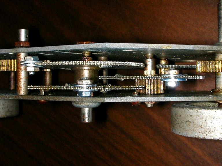
The tuning mechanism on the SX-28 is a marvel of engineering.
It is essentially a gearbox, consisting of two heavy metal plates, a number of shafts and bearings, and some unique gears. Four shafts protrude from the front, and four protrude from the rear. Two of the rear shafts contain heavy flywheels, one for the main tuning and one for the bandspread. These two shafts go clear through, and have the large, "steering wheel" knobs affixed to the front side. The remaining two shafts protruding from the rear are coupled to the tuning capacitors by a separate short shaft and two flexible couplings. The gears that drive these shafts have a bent-up tab that intercepts a pair of screws, thus limiting the rotation to 180 degrees.
The last two protruding shafts in the front hold the dial scales. There are two intermediate shafts for the main tuning that do not exit the mechanism. The main tuning shaft is concentric, the inner shaft carrying the knob on one end and the flywheel on the other, while the outer shaft carries the metal logging scale behind the tuning knob, and actually drives the gearbox. There is a clutch between these shafts, which allows the main tuning to be locked. More will be said about this clutch later. The bandspread shaft uses a dial cord and pulley to operate a single conventional gear set. Bear in mind that for tuning, the variable capacitor rotates 180 degrees through its travel, while the dial scales rotate through approximately 355 degrees, making some kind of gearing necessary. It takes 15.5 turns on the main tuning knob to get from one end to the other, while the bandspread knob requires 5.5 turns.
The ratios used and the method of construction was carefully thought out by the Hallicrafters engineers. If you ever use an SX-28 in good condition, you quickly realize how smooth and effortless the tuning actually is. With a flip of either tuning knob, you can send the dial from one end to the other just on the momentum of the flywheel. Doing this will not harm the mechanism, as the torque allowed on the main tuning is limited by the clutch, and on the bandspread tuning by the "slip" of the dial cord at the extremes of travel. This feature is one of the things that give the SX-28 its character. The smooth tuning is the result of the use of ball bearings for the main tuning shaft, and anti-backlash gears.
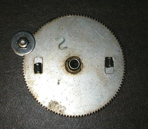
And just what are "anti-backlash" gears? Any ordinary meshing gears have some "slop" in their action, which becomes worse as they wear. To eliminate this effect, on anti-backlash gears, the larger gear on a meshed pair is split into two thin gears. One of these gears is anchored to the driven shaft, while the other has a clearance fit. The two gears are placed adjacent to each other, and coupled together by one or more springs.
Before meshing the gear set, the spring-loaded gears are pre-tensioned so that when engaged, the teeth are in constant contact with the mating gear. Consider that the SX-28 main tuning shaft goes through three sets of gears on its way to the tuning capacitor. Any "slop" here would add up and cause a real problem.
How to Begin?
So now that we have a rough idea of how the gearbox is supposed to work, just how do we go about getting a rusted one to work again like it did when it was new? Yes, we could give it a bath in WD-40, or soak it in a pan of penetrating oil for a few days, but at best, these techniques will yield marginal results. Any solvent will dissolve the existing grease, which is almost impossible to replace from the outside. You might free up the mechanism, but it will never be silky smooth as it should be, and most of the corrosion will be difficult or impossible to remove. It would seem that the only way to properly restore the action of a gearbox in this condition would be to disassemble it, thoroughly clean it up, and reassemble it with some fresh lubricant.
But wait! If we take it apart, those anti-backlash gears that we know and love are going to lose their tension, and how in the world are we going to get it back together? While we might wrestle the gears with protruding shafts into place somehow, what about the intermediate ones whose shaft ends do not exit the housing? The bandspread dial cord is not a problem as it is easy to re-string, and should be re-strung anyway, but those darn gears are a puzzle. The more I thought about it, the more I wondered how this mechanism was put together in the Hallicrafters factory back in the early 40's.
I made an attempt to locate an ex-Hallicrafters employee who might know how the gearbox was put together. This search was possible because the company I work for had started its life in the old Hallicrafters Plant #1, and some Hallicrafters employees had joined the new company. Many of these are now retired or deceased, but a few remained. I asked them all, including the retirees, but none had been with the company when the SX-28's were made. My last lead was one of the former engineers, but by the time I found where he had been living, he was already deceased.
I was forced to conclude that there was no one still living that knew how the gearbox was originally assembled, or how it could be serviced, so I was on my own. I sat down with the rusted gearbox and brainstormed schemes for taking it apart and putting it back together.
My first scheme was to take it apart in a plastic bag, ignoring the unloading of the anti-backlash gears, but being certain to catch the loose ball bearings, springs and any other parts that might fall out. I would then take each anti-backlash gear pair, replace the springs if necessary, twist the pair until the springs were compressed slightly, clamp the pair together with the teeth aligned, then drill a small hole straight through both gears. This hole would then be fitted with a pin, which would hold the gears tensioned until they were reassembled, at which point I could reach in with a pair of needle nose pliers and pull the pins out.
It seemed like such a good idea, I looked for such holes that might already be in these gears, thinking I might have discovered the secret. But, I found no pin holes in any of the gears. When I discussed the idea with a mechanical engineer, he pointed out that the anti-backlash gears were probably hardened steel, since they meshed with a brass gear, and this combination was common to minimize wear on both. He thought I might have considerable difficulty drilling holes in these hardened gears, so I looked for a different solution.
The basic problem was to find some simple way of holding the spring-loaded gears from releasing their tension during disassembly and reassembly. I tried some readily available devices like heavy paper clips, but was not confident that these would hold. Eventually, I came up with the idea of using a "clamp" made up of a hex-head screw, a pair of washers, and a nut. These clamps could be put on the readily accessible gears with a pair of nut drivers, and on the harder to reach internal gears with a pair of needle nose pliers and an ignition wrench. Once in place and tightened, the primary problem would be solved and disassembly could proceed. It would also be possible to put more than one clamp on each gear should I feel this was necessary for safety. Once I tried putting the clamps in place, I found they were quite secure and that one on each gear would probably be sufficient.
Disassembling the Gearbox
If you have followed this far, and you have decided to disassemble your gearbox, start by labeling the shafts that have the anti-backlash gears.
Use stick-on labels for the gears that match these numbers. (You can remove these labels and number the gears themselves after you get them out.) At this point, get a jar in which to place small parts. Make a sketch of the stringing of the bandspread cord, and then remove the cord, putting the spring in the jar. Put a temporary knob on the front of the bandspread shaft, back out the two setscrews on the flywheel, and work the flywheel off the shaft. The back of the shaft, where the flywheel was attached, should be smoothed with sandpaper or a fine file to remove burrs left by the setscrews. This will allow it to slide easily through the bearing hole in the steel plate.
Remove the main tuning flywheel by backing out the setscrews, then unscrewing the flywheel from the back of the shaft. Again, a knob placed temporarily on the front of the shaft may help. The "clutch" washer is now removed, and usually some shim washers underneath. Make a note of the order of this assembly. Put the parts in the jar. When the two large plates are separated, the shafts driving both tuning dials, and the bandspread tuning shaft will remain captive to the front plate, due to the use of "C" washers on the shafts, which should not be removed at this time. The shaft driving the bandspread tuning capacitor will remain captive to the rear plate for the same reason.
Now we come to the moment of truth. Before going any further, be sure you have labeled the idler gear shafts and the gears themselves. It is wise to be confident you can reassemble the gearbox before you take it apart! If you have doubts, read through this entire procedure several times. If you still have doubts, perhaps the WD-40 approach would be safer.
Be aware that there are 47 ball bearings that will become loose when you separate the plates. Lose any of these, and you could be in serious trouble. Depending on the condition of your gearbox, some of these loose bearings may remain stuck in the grease, or on the ends of the idler shafts, but don't count on it.
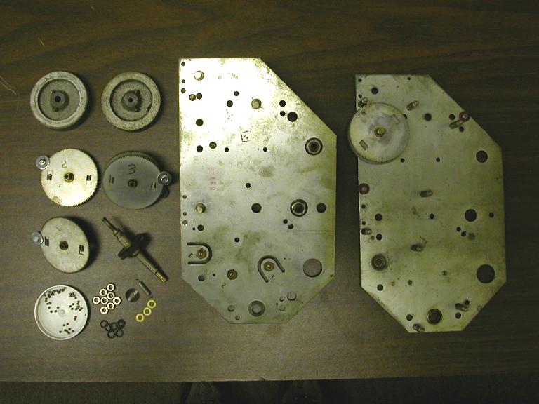
To separate the plates, set the unit down in a plastic bag or baking pan with the front side up. Remove eight 5/16" nuts and their associated lockwashers. Put them in the jar. Be very careful not to disturb the nuts that serve to adjust the bearings for the main tuning intermediate shafts. If you use a 5/16" nut driver or box wrench, it will only fit the nuts you want to remove. Very carefully begin separating the two plates. The two intermediate gears will come out first, followed by the main dial drive gear. The intermediate gears (Shafts 1 and 2) have a larger .125" ball bearing at both ends, which will probably stick to the end of the gear shaft. Remove these and put them in the jar. The main tuning capacitor drive gear (Shaft 3) will have one larger bearing on the end, remove this and put it in the jar.
As you continue to separate the plates, the main tuning shaft will become loose, and eventually the plates will come apart. There are 14 small .0937" ball bearings at the front and rear of the main tuning shaft and 14 of the same bearings at the front of the main tuning capacitor drive shaft. Collect all these bearings carefully and put them in the jar. You should have 42 small bearings and 5 larger bearings. (If you have one or two less small bearings, look around carefully, but don't panic, it will work OK without a couple.) You should now have a collection of parts that resembles this.
Cleaning Gearbox Components
Next step is to clean everything as best as possible. Leave the four shafts captive on the two plates unless you absolutely have to remove them. You can free them with WD-40, clean them and lube them adequately even though they are captive. If they are rusted in solid, then you may have to remove them to properly clean them. I have no easy procedure for removing the "C" washer. I've had success with a pair of needle nose pliers, but it's tricky. If you break a C washer, you can steal one from an old potentiometer or rotary switch. If you have to remove the captive shafts to free them, reattach them before proceeding. Use fine sandpaper to polish the opposite ends of the captive shafts, as these will have to slide back in smoothly during reassembly. Carefully clean off any sandpaper residue.
Use your choice of rust and corrosion remover on the plates. I start with Naval Jelly to dissolve the rust, then use carburetor cleaner to remove the residue. Using carburetor cleaner or some similar grease remover, (but NOT gasoline) completely clean out the bearing races, the bushings screwed on to the front plate and the gears and shafts. The concentric main tuning shaft should be separated and both pieces thoroughly cleaned. All the small parts in your jar should be cleaned. A dilute solution of Naval Jelly seems to work well for the bearings, followed by a rinse and thorough drying. If your bearings are really rusted and don't respond to this treatment, you may be able to find replacements at large hardware stores or hobby shops. If your replacements are close but not exactly the same diameter, the difference can be taken up by adjustments.
If the flywheels are rusty, try Naval Jelly, but if you are not happy with the results, consider just painting them with gray primer. Plug the shaft holes with tissue, and mask off a 3/4" circle on the backside of the flywheel with the smaller threaded center hole, so the clutch washer does not ride on the paint.
If you suspect that one or more of the anti-backlash gear sets are rusted together, you will have to remove the clamp and springs, and work some penetrating oil into the gears to free them. Once this is done, replace the springs then rotate the two gears in the direction to compress the springs until they are offset by two gear teeth from the unloaded position and in exact alignment. At this point, the clamp needs to be put back in place. You may find this operation is easier using a small bench vice or even "vise-grip" pliers to hold the gears while you reattach the clamp. I've found a very thin coat of DeOxIt on all the metal parts will keep them from rusting further. Just spray a little on, then wipe it down with an old rag.
You can get more elaborate with the cleaning if that is your personal preference, but what we are after here is just a relatively acceptable looking gearbox that works as well as it did when it was new. Extreme approaches like re-plating or painting require a lot of prep work, and a lot of work after the process. I have not personally tried this, but will be glad to consult with anyone who wishes to take the plunge.
Reassembling the Gearbox
Now that you have all the pieces cleaned to your satisfaction, it's time to put the beast back together. Since we probably don't want to go through this operation again, it's important to select a proper lubricant for reassembly. We need something with sufficient body to hold the ball bearings in place while we replace the shafts, but not so heavy as to cause any drag. Two lubricants I have used are Dow #4 compound, which is a silicone grease, or Texaco Molytex #2. The Dow grease is translucent, so on places like shaft exits it is inoffensive. In addition, it is stable at the higher temperatures found inside tube rigs. The Molytex is messy, but seems to work OK. It is possible there is no single lubricant that is best for all parts of the mechanism, but the Dow compound comes close. You might want to consider something like 80 weight oil for the non ball bearing shafts.
Start by applying lubricant to the captive shafts. You will have 3 captive shafts on the front plate and one on the back plate. If using the grease, work it into the spot where the shaft passes through the plate, rotating the shaft to insure grease gets into the bearing. Wipe off excess. If using heavy oil lubricant, put a few drops on the shaft in the gap of the C washer and work it in. Wipe off the excess. There are two small pulleys on the rear plate that carry the dial cord for the band select mechanisms. These need a drop of oil each.
Now it is time to reassemble the gearbox. If you are not using the original ball bearings and your replacements are sized differently, the numbers called out may be too many or too few. You may need to experiment with one of the shafts, such as the tuning shaft, to determine the optimum number. Put the rear plate up on a couple of blocks with the studs facing upwards. Locate the bearing pivots for shafts #1 and #2 and apply a dab of grease in the recess of the adjusting screw.
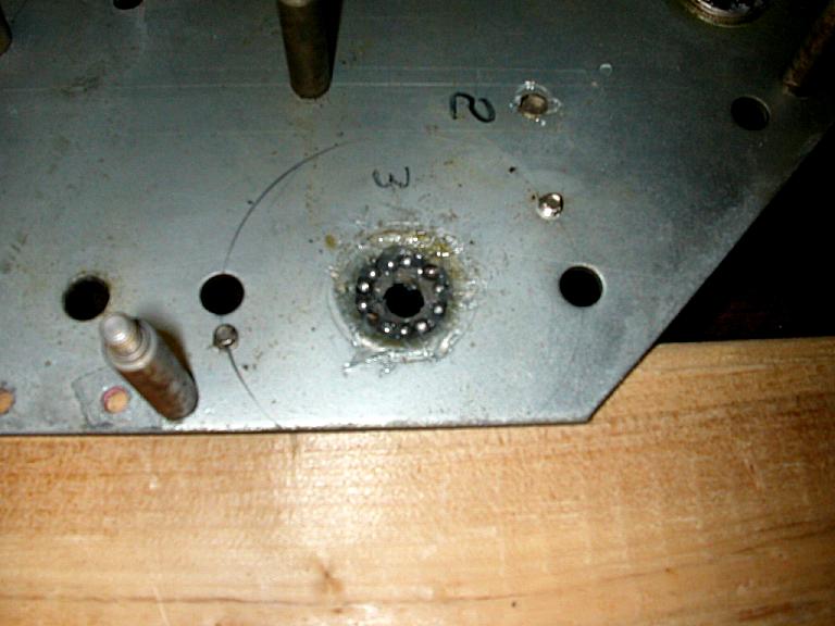
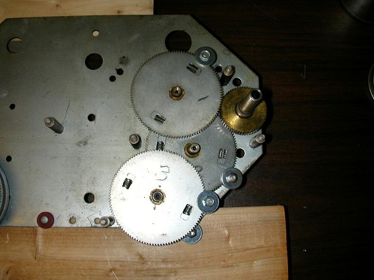
Apply a generous coating of grease around the bearing cup where the main tuning capacitor drive shaft exits, (Marked #3 on photos.) and around the cup where the main tuning shaft exits. Using a toothpick, get small glob of grease on the end then "pick up" a small bearing and carefully place 14 of the small ball bearings into the grease around the tuning capacitor shaft exit cup.
Using the same technique, place 14 small ball bearings around the cup where the main tuning shaft exits. Next, identify gears 1, 2 and 3.
Gear #3 is the double gear with the shaft that exits and drives the tuning capacitor. On the end with the shaft that exits, apply some grease around the spot on the shaft where the diameter increases. You may see a wear line where the ball bearings rode, this is the area you want to grease. Look at this gear from the end with the shaft and note the bent-up tab that is the end stop. Orient the gear so the tab is toward the outside edge of the plate, and carefully set this gear in place with the shaft going through the hole in which the bearings have been placed. Be careful not to dislodge any of the bearings.
Next identify gear #2. This is the gear where the small brass gear is even with the end of the shaft. At the shaft end with the brass gear, put some grease on the end of the shaft and stick one of the larger ball bearings into the recess. Turn the gear over, rotate it so that the "clamp" is near the edge of the back plate, and slip it in place so that the large gear goes in between the two large gears on shaft #3, and the single ball bearing sits in the adjustment screw.
The remaining gear should be gear #1. Put a glob of grease on the end of the shaft that exits from the smaller brass gear, and stick one of the larger ball bearings on to the grease and into the indent on the shaft.
Turn the gear over so the bearing is down and rotate it so that the clamp is near the edge of the plate opposite where gear #3 exits. Place the gear into position so that the brass gear engages gear #2 and the bearing sits in the adjustment screw. The gears will not necessarily hold their positions at this time.
Now locate the main tuning outer shaft, the one that carries the brass gear. It will be installed by itself, and the inner shaft will be added after the gearbox is assembled. On the end with the shorter shaft, put some grease around the shaft where the first diameter change takes place—you will see a wear line where the ball bearings ride. Now carefully put the main tuning shaft in place with the long part of the shaft facing up. It goes in the remaining bearing cup located between two studs at the edge of the plate. The brass gear on the main tuning shaft will eventually engage gear #1. Be sure all the small ball bearings remain in place.
At this point your mechanism should look like this.
Carefully inspect the areas where the shafts pass through the bearing cups and make sure there are no ball bearings out of place. If there are, retrieve them, lift the shaft slightly, and poke them into place.
Next step is to reattach the front plate. This operation is a bit tricky, but if you are careful and follow instructions it should be relatively painless.
If you have not already polished the free ends of the captive shafts do so now, as things have to go together smoothly. Turn the front plate so the free ends of the captive shafts are facing up, and put a dab of grease on the bearing adjustment screws for shafts 1, 2 and 3.
Next, put a generous amount of grease in the main tuning bearing cup, and place 14 ball bearings in the grease as you did in the previous steps. These bearings need to be placed a bit deeper in the cup than the others, but not so deep as to reduce the diameter of the hole through which the tuning shaft passes.
On the front plate, put a little grease around the main tuning shaft where the diameter enlarges, holding the shaft in place while applying the grease. Put a dab of grease on the ends of shafts 1, 2 and 3, and stick the remaining larger ball bearings into the recess on the ends of these shafts.
Now position the front plate over the back plate so the shapes match. The bandspread tuning shaft will pass through the rear plate first. Line it up and slowly start lowering the top plate. Carefully guide the tuning shaft through the bearing hole, being careful not to dislodge any bearings from the grease. You will need to align the two other captive shaft ends into their holes in the rear plate, and guide all three gears with the single ball bearing ends into their respective sockets. (Shafts 1, 2 and 3.) A pair of needle nose pliers will help here. Work from the bandspread shaft towards the main tuning shaft. Watch carefully to see that all shaft ends go where they should, and that no small ball bearings are displaced on the main tuning shaft. When you get the threaded studs started through their holes, you are almost there. Put a nut loosely on the stud near the bandspread shaft when you can see the threads.
When you have worked everything into place, put a couple more nuts on just finger tight so you can inspect things. Make sure all the shafts are in their bearings, and that no small bearings have escaped from the main shaft. If all looks well, and you are using the original bearings of the correct size, place a lock washer and nut on the remaining studs and tighten slightly. Remove the previous finger tight nuts, put a lock washer under them, and tighten them slightly. At this point, all the shafts should have some movement, though it will be restricted on the main tuning by the clamps. If all goes well, tighten the eight nuts securing the plates together.
If you have substituted the bearings, you may have some binding or some slop in the mechanism after the first tightening of the eight nuts. In this case, you will need to adjust the play in the bearings. The large tuning shaft is adjusted by loosening the 3/4" nut holding the bearing cup on the back plate, then adjusting the clearance by turning the inner, slotted boss. You can use the tips of needle nose pliers for this. Adjust until there is no binding, but save final adjustment for after all the securing nuts are tightened. The adjustments for shafts 1, 2 and 3 are on the opposite side, right next to the numbers for these shafts put on earlier. (See photo 4.) To adjust the clearance, you need to loosen the 3/8" nut, adjust the screw, and tighten the nut while holding the screw from turning. Once you have clearances roughly set, tighten the eight nuts.
If you have problems getting the plates together using the above procedures, here is an alternate that also works. Follow the procedure as outlined above but leave out gears 1 and 2. You still need to put a dab of grease on the shaft pivots. After you have the plates screwed together, remove the pivots labeled 1 and 2 on the front plate. Grease the shaft ends and place the bearings on gear #2 and carefully slide it into place with the orientation described earlier. You can do this using needle nose pliers, being careful not to lose either ball bearing on the shaft ends. Line up the shaft by looking through the hole where you removed the #2 gear pivot. Once lined up, you can replace the pivot. Tighten down the screw until it stops, then back it off about 1/8 turn and tighten the nut. Check to be sure the gear does not bind. Repeat this procedure with gear #1. Be careful the ball bearings don't get caught in one of the many holes in the plate as you are positioning the gear.
Once you have everything in place, and the eight mounting nuts tightened, turn the assembly over and lubricate the captive shaft ends. This would be the bandspread tuning shaft, and the two shafts near the top that drive the dials on their opposite ends. Once this is done, you can remove the clamps on the anti-backlash gears. For final clearance adjustments and gear lubrication, you might find it handy to back out the screws that limit the rotation of the main tuning capacitor shaft. These screws are found on the back plate, on each side of shaft #3. They are the only screw heads on the back plate that don't hold anything.
With these backed out, the gears will rotate freely without stopping, making final adjustments on bearing clearances and lubrication easier. There should be no binding, nor should there be any slop. If you try to wiggle gears 1 and 2 and see any movement at the ends, there is too much clearance. The gear teeth are lubricated by putting a little grease on the end of a flat blade screwdriver and touching the gear teeth while rotating the main shaft. You need only grease the anti-backlash gear teeth; the lubricant will transfer to the smaller brass gears. We don't need a lot of lubricant here, so wipe off the excess. Use the same procedure for the bandspread gears. After lubrication, turn the main shaft until the bent up pin on gear #3 is visible, then run the limit screws back in.
Restringing the Bandspread Dial
Congratulations! The hard part is over. The bandspread dial cord is next.
For the bandspread cord, I use 45-pound test woven Dacron fishing line. If you have had success with something else, feel free to substitute, but remember it is not easy to get to this cord once the gearbox is back in the receiver. A stiff wire with a hook on the end, a pair of needle nose pliers or a hemostat will aid in fishing the cord through the mechanism.
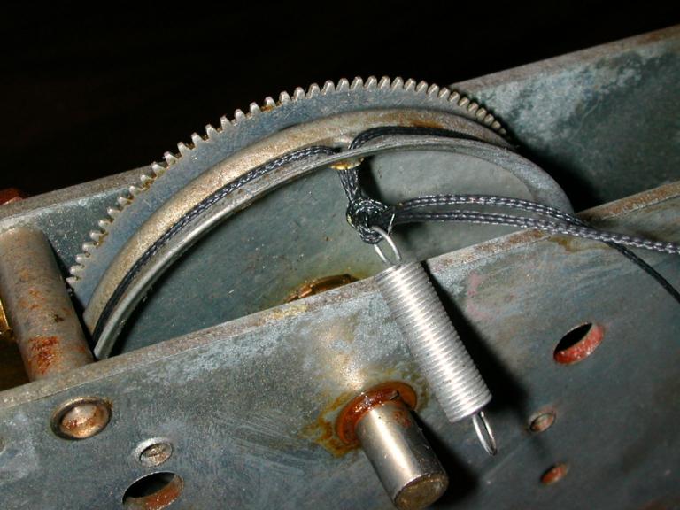
To begin, set the gearbox up on its side with the bandspread pulley at the top. Moisten a cotton swab with alcohol, then reach in and clean any grease or oil off of the narrow portion of the bandspread tuning shaft. This is to insure a clean surface for the dial cord. Cut a piece of dial cord about 14" long. Rotate the bandspread pulley to place the cord hole at the top. Poke one end of the dial cord through the hole, bring it out the back of the pulley about 3", lay it against the back plate and loosely tape it in place. Take the free end and drop it down towards the bandspread shaft, being careful to keep it toward the inside of the two fixed studs. The cord needs to go past the side of the bandspread shaft towards the INSIDE of the gearbox.
Working from the open side of the gearbox, bring the free end up to the bandspread shaft, over the top and away from you, winding towards the rear of the gearbox. In other words, you are making a clockwise turn around the shaft as viewed from the rear. Drop the end down and fish it through one more time in the same manner as before. Now bring the end of the cord around the bottom of the bandspread shaft in the same direction and fish it up along the right side of the bandspread pulley, poke it through the hole, and carefully take up the slack. To review, the cord should now come out the hole in the pulley, go to the left, or counter clockwise around the large pulley, go down to the bandspread shaft, make two and a half turns around the shaft in a clockwise direction as viewed from the rear, then come up the opposite side of the pulley and go back through the hole.
The cord should not touch anything on its way to or from the bandspread shaft. Locate the dial cord spring that was removed in the beginning. Remove the piece of tape holding the end of the cord and pass both ends of the cord through the loop on the end of the spring. Tie a loose plain old granny knot, working the knot up as close to the dial pulley as possible before tightening.
Put a drop of Duco cement or Elmer's glue on the knot and let it dry. Don't cut the excess string yet.
Attach the opposite end of the spring to the hook on the bandspread pulley. You may need to rotate the pulley slightly to easily reach the hook. Once you have the spring hooked, try out the action. The cord should not loop over itself around the shaft, and there should be no rubbing or binding anywhere. Tension on the cord should be consistent.
If there is inadequate tension, you can undo the knot with a pin and tie it closer to the pulley, or you can take a few turns off the spring, bending the last turn to form a new loop. If you have a loop crossing around the shaft, take the spring loose and straighten out the cord path, then hook the spring again. Verify that turning the shaft clockwise from the front results in counter clockwise movement of the pulley that drives the tuning capacitor. The shaft that drives the dial will turn the same direction as the bandspread shaft. Once you are happy with the operation of the bandspread, trim off the excess cord ends. The bandspread stringing is now complete.
Final Touches
All that is left at this point is to attach the flywheels. Locate the inner tuning shaft, put a knob temporarily on the end, and apply a thin coat of grease to the narrower part of the shaft, stopping at the screw threads. Insert the inner shaft into the outer shaft as far as it will go. Wipe off any excess grease. Take the shim washers and place these over the protruding threaded end of the shaft. Follow this with the bent "clutch" washer. Take the flywheel with the smaller threaded hole, and back off the setscrews slightly. Screw the flywheel onto the shaft until there is some compression of the clutch washer. Temporarily tighten one setscrew. Turn the main shaft via the knob counter-clockwise until the tuning gear pin hits the limit screw. Continue turning the knob to get a "feel" for the clutch tension. You need enough tension to turn the tuning capacitor, but not so much that gear #3 is stressed at the end of travel.
The clutch tension is determined by how far the flywheel is screwed onto the shaft, so you can adjust it after everything is put back together if you need to. Once you are happy with the setting, tighten the setscrews on the flywheel and remove the temporary knob. Place the other flywheel on the back end of the bandspread tuning shaft, position it to leave about 1/8" clearance between the back plate and the back of the flywheel, and then tighten the setscrews. This completes the rebuild of the gearbox.
Epilogue, Acknowledgements, References and Comments
Shortly after starting this project, I realized I was entering the area "where no one had been before." I saw an opportunity to contribute something significant to the pool of knowledge from which I drank freely in the past. I strove to provide sufficient detail to insure anyone with the courage to start down this road would end up at their desired destination. Some may think I got carried away, and that is certainly possible. In the course of writing this article, I completely disassembled and reassembled my gearbox five times, each time discovering something I missed, or that needed clarification. I'm sure there is still room for improvement, and I would be interested in hearing from anyone who has suggestions or comments. We are also searching for sources for replacement precision steel balls in small quantities. This article does not address the stringing of the band indicator pointers, which has been covered elsewhere. If you can't find this information, drop me an E-Mail.
I was greatly encouraged, inspired or assisted by a number of people in the course of developing this article, and I would like to acknowledge them at this time.
- My wife June, who has put up with a crazy person for over 30 years.
- My old High School teacher, Jack Brown, who first encouraged me to write.
- Duane Fischer and Fred Mooney, who are making this available on the web.
- Phil Nelson, for his excellent website and fine documentation on the SX-28.
- Eiichi Tamura, who took all the photographs.
References
Precision stainless steel .0937" balls can be purchased online from
Flexbar. The .125 balls are available at larger Ace Hardware stores.
Comments on preliminary draft
"The article is outstanding. You'll be the first fellow I've seen in all the years since my SX-28 and I were built to publish this vital, almost mystical information. The screw clamp for holding the split gears at tension is elegantly brilliant!" (Gerry—W4YMF)
"Thanks for your help. The procedure of clamping the backlash gears worked like a charm. The gear assembly seems to be working smoothly. Good luck with your document." (Charlie—K4GBM)
Revisions
- 10/04 - Minor text revisions and corrections.
- 12/04 - Bandspread stringing instructions revised.
Copyright Information
This article is reproduced here by permission of Hallicrafters Collectors International
(http://www.w9wze.org/). You may print the article
for your personal use, but no part may be reproduced or distributed for other purposes
without the express permission of the author, Doug Moore.
This radio construction project, including all descriptions, diagrams, photos, and the underlying electronic design, is published here for the noncommercial use of radio hobbyists. You may print and reproduce these project instructions for your personal use. Commercial use of this material is strictly forbidden.
|