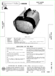
Sony Model 8-301W Portable Television (1961)


The Sony 8-301W transistor television was introduced
in 1961 and it sold well, considering its hefty price of $249.95.
The distinctive profile makes it a favorite of collectors.
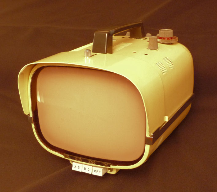
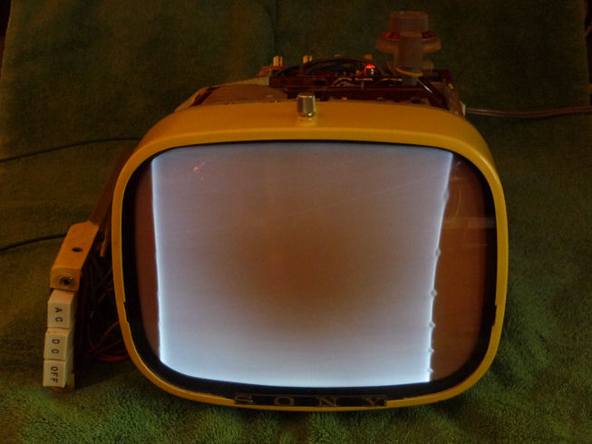
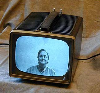
Here's a photo of my 8-301W after restoration:
The World's First . . . Something
Urban Legend #1. Sony advertised this TV as "all
transistorized," which stretched
the truth a mite. Although the 8-301W has many transistors, it uses two
small 1DK1
tubes as high voltage rectifiers. That's three tubes if you count
the picture tube.
Urban Legend #2. Some people call this the first transistorized TV, but that's wrong,
too. The
Philco Safari
was introduced in 1959, two years before this set. Like this one, the Safari uses two
rectifier tubes in addition to many transistors.
Urban Legend #3. Another mistaken claim is that the 8-301W was
the first portable direct-view TV. (Direct view means you view the picture
tube directly, rather than in a mirror as with the Safari.) Portable direct-view
TVs were sold in the 1940s by
Sentinel and
other companies.
A more truthful description of the 8-301W might be, "the first mostly-transistorized
portable TV that Sony sold in the United States."
Catchphrases aside, this is an interesting example of early transistor TV technology,
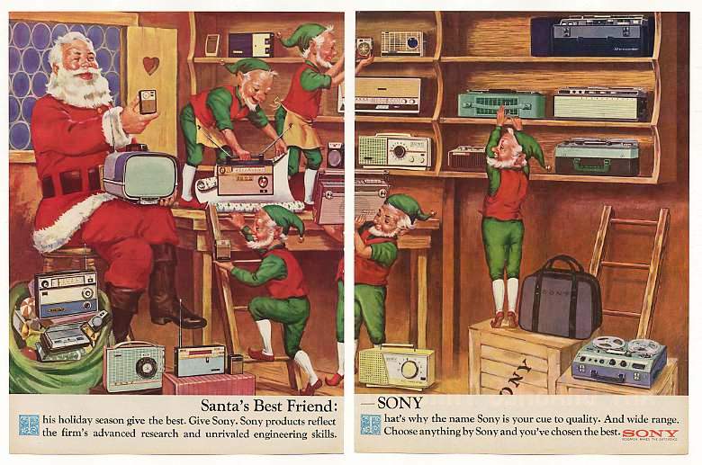
and I was curious to see how well it would work, once restored. In this whimsical
magazine ad, Santa holds an 8-301W on his lap while elves busily stock the shelves
with other Sony products.

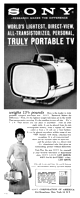
This ad from the October, 1961 issue of Ebony magazine gives more
details. The list price was $249.95 and the optional rechargeable battery
cost another $29.95.
Description
The 8-301W has an all-metal case with an adjustable hood. It's a true
portable, using either AC power or a 12-volt DC source.
Surprisingly heavy for its size, it tips the scales at more than 13 pounds,
with another 4 pounds for the battery pack.
The factory paint is a textured gray that makes the TV look more
like a piece of test equipment than a snazzy portable. A previous owner
painted mine pale yellow, which I like better. Here is a view of the back.
As noted on the backplate, the TV uses 23 transistors, 18 diodes,
and two tube rectifiers. The power socket is at upper left.
Four small knobs on the back are labeled Gain, Brightness, Vertical,
and Horizontal. The 8-301W lacks a contrast control.
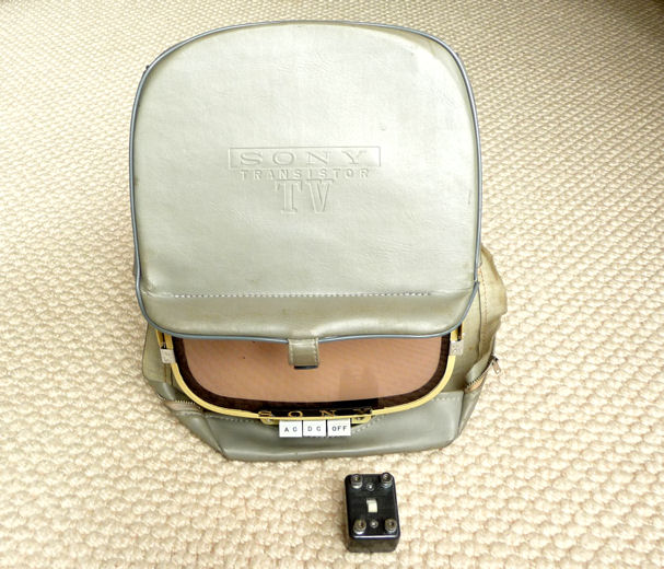
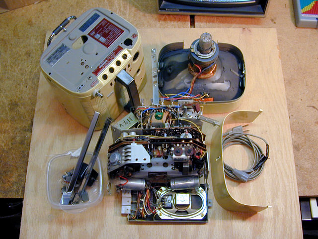
The TV came with a zippered vinyl carrying case. I also have a small
Sony adapter for connecting an external antenna.

The TV has an oddball power connector. If you see burn marks around
the connector, check the power supply carefully. Somebody might have
tried to hot-wire it with a homemade cable and guessed wrong about the
connections. Sony sold this television in Europe as the 8-301E,
using 220-volt rather than 120-volt AC power.
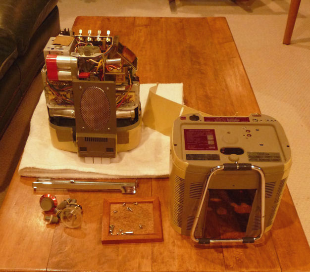
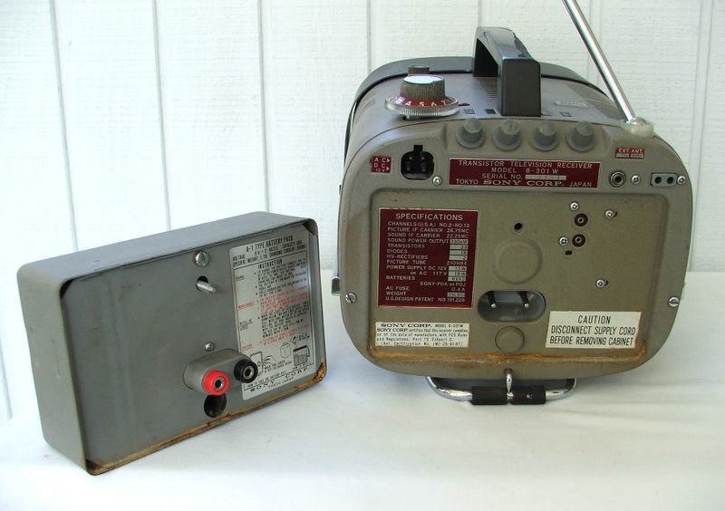
The large battery pack is seen in the following photo of someone else's
TV. Many of these batteries have been discarded by now, as they eventually
lose their ability to recharge.

The previous photo also shows the standard factory paint, a medium gray
with a slightly textured "wrinkle" finish.
Here is the 8-301W service manual; to download it, right-click on the
icon and choose Save Target As:
The 8-301W must have been very popular, since they are still plenty of them
floating around. If you pay much more than $100 for one, you're not shopping
very carefully. I have seen scruffy ones at swap meets priced as low as $20
with no takers.
Disassembly
Begin disassembly by removing the screen hood and chrome trim
strips. The strips pull off after you remove two screws in the
back. Then you lay the TV down on its face, pull the knobs, remove screws
from the back and sides, and slide the case up and off. The case may
be stuck on the front rather tightly. Don't damage things by prying
it off carelessly.
The speaker and power switches remain attached to the chassis
by a set of wires and needn't be removed from the speaker plate.
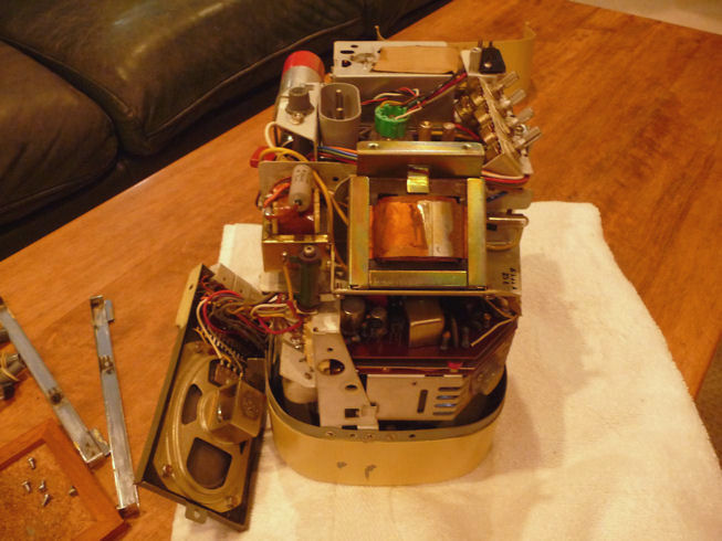
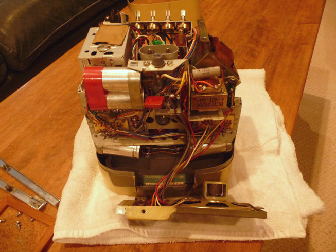
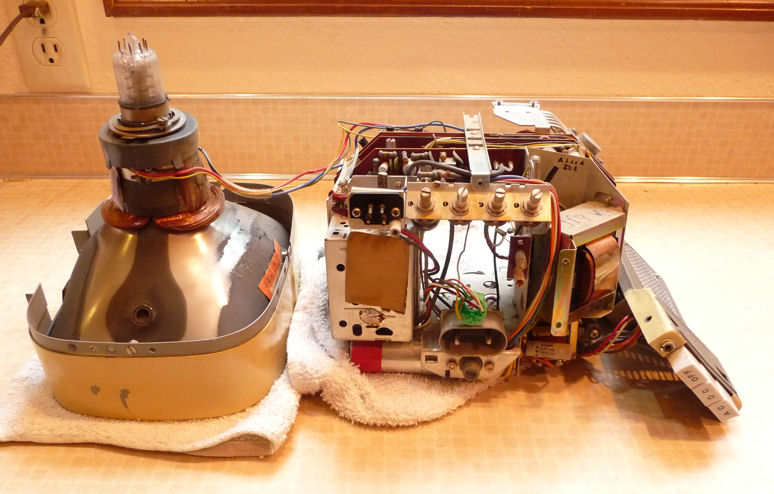
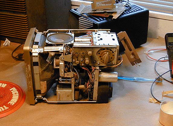
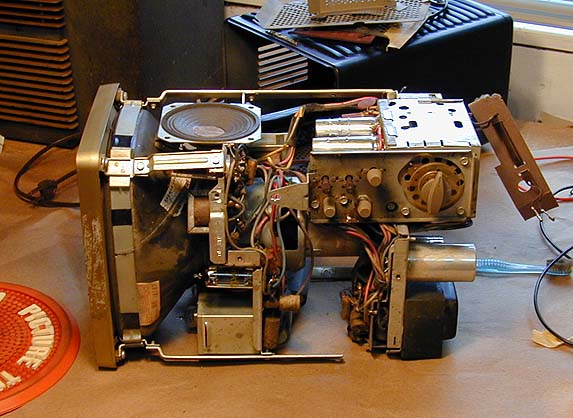
Here is the chassis from each side after I removed the case.


The second photo shows four fat capacitors used in the power
supply. The picture tube socket is bright green. This
TV uses dozens of small electrolytic capacitors, and you can see several
of them clustered on the tightly-packed circuit boards.
Even using miniature (for the time) components, it was quite a trick
to cram an entire television into the space around the neck of the
picture tube. A customer's dream . . . and a serviceman's nightmare!
First Power-Up
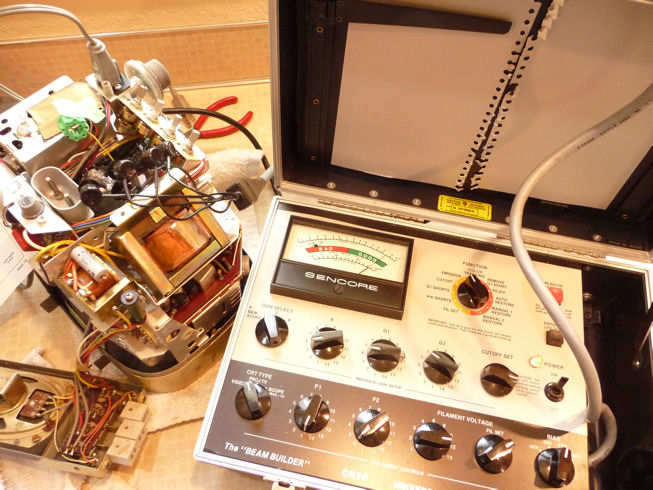
Before getting too carried away, I tested the type 210HB4 picture tube.
If the CRT is dead, this TV may not be worth restoring. My Sencore CR-70
tester doesn't have a socket for this tube, so I used the universal
adapter, which has little probes that clip to the CRT pins.
The test showed strong emission, a welcome sign. The needle moved well
up into the green Good zone. When I powered up the
television, here's what I saw:
The audio came through loud and clear, indicating that the tuner and
audio circuits are working, at least marginally. The raster was dim, with no sign
of the broadcast image, as if the video signal simply wasn't getting through.
It's not surprising that the TV needs work. Early solid-state
televisions use lots of little electrolytic capacitors, and after 50 years,
one would expect some of them to fail from drying out over the decades.
Cleanup and Further Investigation
The next step, routine in all restorations, is to
clean the controls and anything else that needs it.
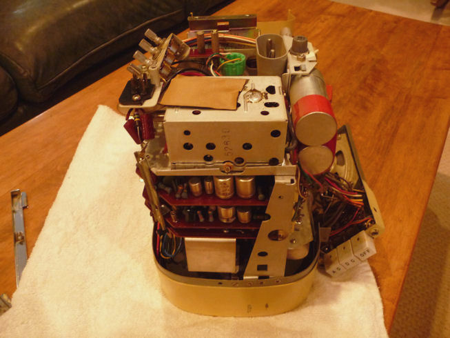
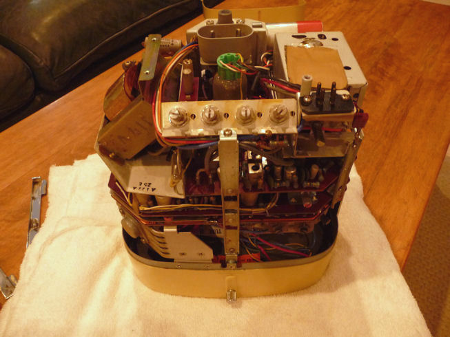
The chassis lifts off the picture tube as a unit after
you remove several screws and free the yoke and CRT socket.
Don't forget to pop out the CRT anode, whose lead is very short.

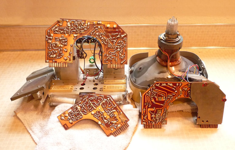
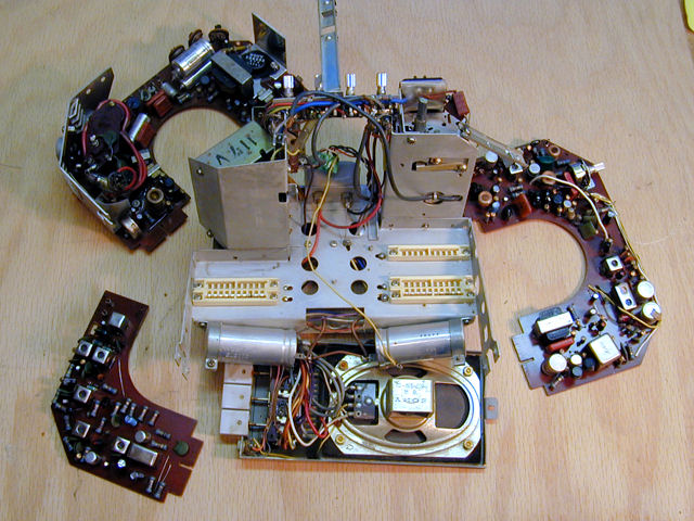
The three circuit boards unplug from the chassis after you remove
a couple of clips. They comprise functional modules for
vertical/horizontal sweep; video IF; and
video output, sound, sync, and horizontal AFC.
This modular design speeded up factory service. The technician
could quickly identify which board contained the problem, plug in a new
one, and pitch the old board into a bin to be reconditioned
(or perhaps just discarded).
Modular design makes this TV tricky for a hobbyist restorer,
compared to an older tube set. When the boards are plugged in, they're
so close together that you can't reach anything to test voltage or check
waveforms on an oscilloscope. With the boards unplugged, it's impossible
to power up the TV for diagnostics unless you have a set of extension cables
with matching sockets and plugs to hook everything together on the workbench.
Sony factory techs must have used special cables like that. I'm not about to build a set
of custom cables that I'll never use again, so I'll do the best I can, testing
components passively on the detached boards and putting the TV back together when
I want to see it play.
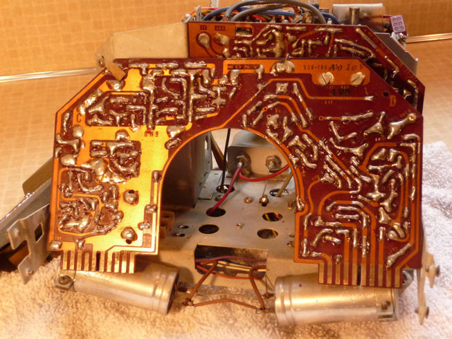
Mediocre Construction Quality
My first look at the boards did not impress me with
Sony's construction quality.
This circuit board has big, sloppy globs of solder and the board's
contact fingers are dark with corrosion:

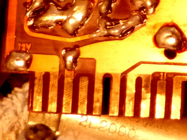
A close-up identifies the culprit. Check out these
greasy fingerprints left behind by a careless assembler.
Hadn't gloves been invented by the 1960s?
Although these prints began as grime, they eventually
corroded the contact metal. Chemical cleaning didn't touch
this hard corrosion. I gently burnished it with a Dremel power tool.

I normally don't use such methods on contacts, which are often
plated with a thin layer of precious metal. These contacts are plain
old copper, however.
I then cleaned the controls and reassembled
the TV. It showed no dramatic improvement, but cleaning did eliminate slight
scratchiness in the Volume and Gain controls.
Replacing Electrolytic Capacitors
Replacing capacitors is a common procedure, so if you're unfamiliar with
the process, refer to my recapping article for
basic how-to advice.
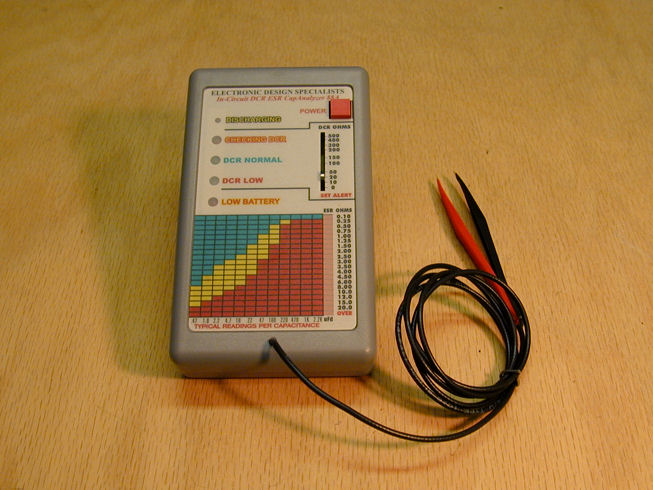
This TV sat around for about a year, until I acquired an instrument that
greatly simplifies restoring solid-state electronics. It is an EDS
88A capacitor analyzer:

Also known as an ESR tester, the 88A can test electrolytic capacitors
without disconnecting them from their circuits, a time saver when
a device contains dozens of electrolytics.
When I pulled the PC boards and started testing, around
twenty (!) of the old caps were clearly defective. No wonder the screen
showed only a blank raster. I'm surprised that the TV showed any signs
of life at all.
I marked the top of each bad cap with a red X and dove in. Just
as with tube electronics, the modern caps are smaller
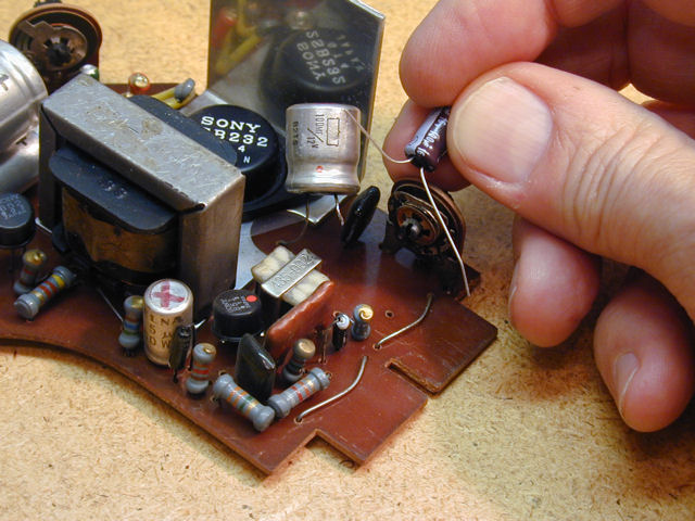
than the originals. Here, I have disconnected one leg from an original 100-mfd
capacitor, holding its replacement nearby.
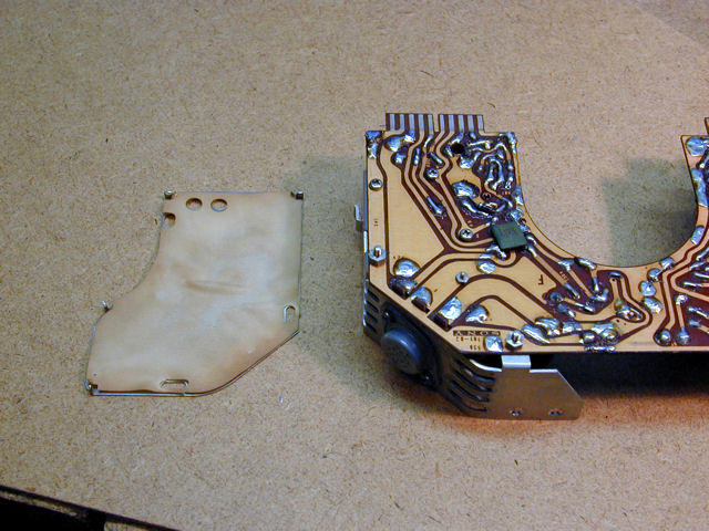
Access to a couple of the bad caps was blocked by this shield, located on the
foil side of the high-voltage section:

To remove the shield, you unsolder four lugs from the board and unscrew two
insulating spacers. Don't forget to reinstall the spacers when you're finished
here. They prevent the board from shorting against the shield.
Here are the PC boards after installing a number of new electrolytics:
Reassembling the 8-301W
I'm ready to reassemble the television for a tryout. The first step is to plug the boards
into the main chassis and connect a few cables. The smaller video
board goes behind the two larger boards.

The boards are installed and I have gathered the rest of the parts.

Final assembly is done with the CRT face-down on the workbench. The main
chassis is carefully lowered over the CRT neck and screwed onto the CRT frame.
Then the main housing is lowered and screwed in place. Lastly, the speaker
panel is screwed into the bottom.
First Picture
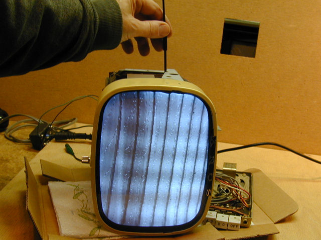
Enough messing around. Let's see how the TV works with fresh capacitors.

Not perfect, but not too bad, either. Yes, we're lacking horizontal
sync, but the picture has good brightness, contrast, and focus. The channel
selector and fine tuner are working well, and the audio is excellent.
The basic recapping made big improvements.
The blizzard of horizontal lines indicates that the horizontal frequency
is far off the mark, which is 15,750 cycles per second. In the next photo,
I am using a nonconductive tool to adjust the horizontal frequency control
on the sweep chassis (now, the picture tube is lying sideways):
If you compare the two previous photos, you'll see that the number of slanted
bands is fewer in the second shot, a sign that the adjuster is taking
us in the right direction. (Eventually, the picture would resolve into a single band and
the picture would straighten up.) The adjuster soon hit the end of its
travel, however, so adjustment alone won't solve this problem.
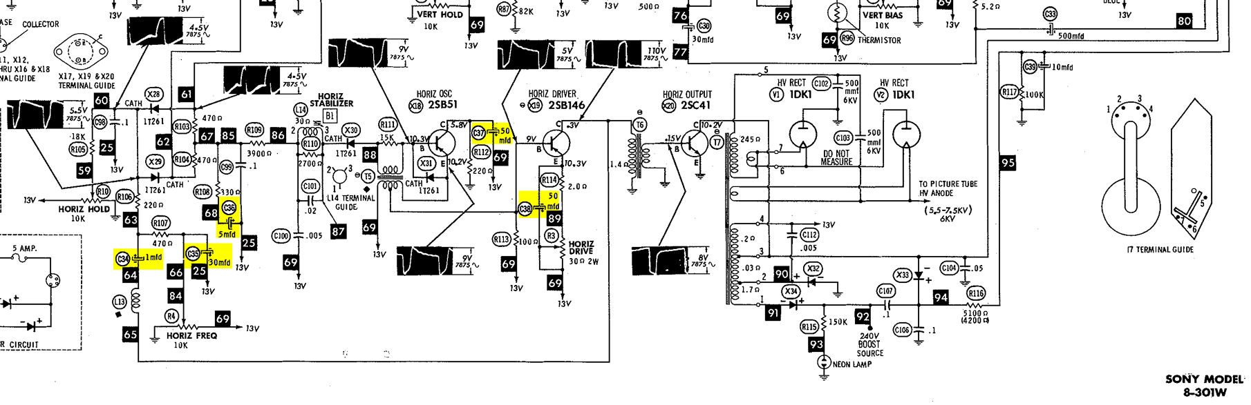
Then I remembered that I had replaced one electrolytic with a value different
than the original. It is capacitor C34, one of those shown with yellow highlighting
to indicate that they were replaced:

The original capacitor has a value of 1 mfd, rated for 12 volts. I couldn't find an
exact replacement at Mouser, so I had used a
slightly higher value, 3.3mfd/16v, hoping that this would work.
Looking at the schematic, you can see that C34 is near the horizontal
frequency control, and it's on a line bringing some sort of feedback from
the horizontal driver transistor (X19) back to this area where frequency
is determined. My replacement is more than three times the specified
value. Could this be messing up the frequency?
Generally speaking, where a capacitor performs a simple coupling function—passing
a signal from one circuit to another —its value isn't that critical.
However, if it's part of a tuned circuit, designed to resonate at a certain frequency,
the value is more important.
This capacitor acts as a coupler, passing a feedback signal from the drive transistor,
and it's also paired with L13, described as a peaking coil in the manual.
This type of horizontal circuit was unfamiliar to me, so I called on the VideoKarma
solid-state TV forum for advice. The discussion
suggested that the incorrect value might be causing the frequency problem, so I ordered
a 1mfd/25v capacitor.
Fixing the Horizontal
A couple of days later, I installed the new 1-mfd capacitor, but that alone
didn't cure the horizontal problem. A couple of forum members suggested looking at
non-polarized capacitors C98, C99, C100, and C101, all located in the horizontal
AFC section.
At the same time, I found out about a new electronics store in the area. Off I went
for a field trip, returning with a little sack of components.
First to go were C100 (.005) and C101 (.02). The store didn't have any .02 caps,
so I made one by wiring two .01 caps in parallel. The photos show the corner
of the sweep board before and after the replacement:


Bingo!
My doubled-up cap worked fine. With only a slight
turn of the horizontal frequency control R4, the picture snapped into place and
held stable.
The picture is snowy because I'm receiving a broadcast from the
transmitter on
the other side of the house, which is not strong at this range. Plus, there's plenty of RF interference in my workshop from sources like compact fluorescent light bulbs.
The signal from my test pattern generator is stronger, requiring that I turn
down the Gain control quite a bit. It also lets me judge the Sony's screen geometry:

The vertical centering and linearity are quite good. The center dot is
at the middle of the screen and the squares are about the same size at
top and bottom.
The horizontal linearity is fairly symmetrical, but when the dot is centered,
there are eight squares on the left side of the screen, and ten on the right.
You can see that squares near the left margin are stretched more than squares
in the center zone. This is common with old tube TVs, which, if they have
a linearity defect, invariably stretch the left side. This TV, however,
also shows stretching near the right margin, as well as slight warping of the rightmost
vertical lines.
In the VideoKarma discussion, Hugh, who had restored several of these little
TVs, remarked that their horizontal linearity simply isn't great. He also
offered advice on finding the best compromise by adjusting the Horizontal
Drive and related controls.
I did the best that I could, understanding that
perfect screen geometry might be unobtainable, given the TV's design limitations.
This TV has fewer adjusters than many old tube TVs (there is no Width control,
for instance). Its adjusters are also quite interactive, meaning that
adjusting one parameter changes another—not always in the way
that you would want. For example, the Gain control has a noticeable
effect on the vertical warping near the right screen margin.
Finishing the Recap
I had already ordered enough new electrolytics to completely recap
the TV. I re-checked all of the remaining caps with my ESR tester
and decided that my earlier tests had been a little too lenient. The closer I
looked, the more marginal caps I found, so I decided to finish the job.
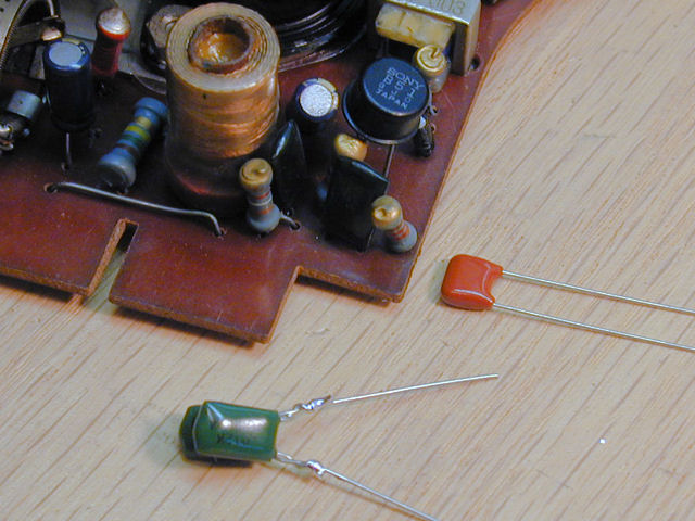
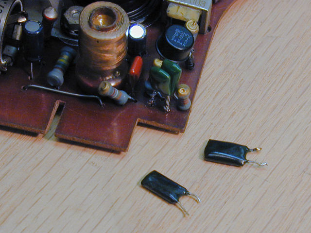
In the first photo, I have clipped the ends of three electrolytics, making it
easy to remove their clipped stubs from the foil side of the board.
The second photo shows the new parts in place.


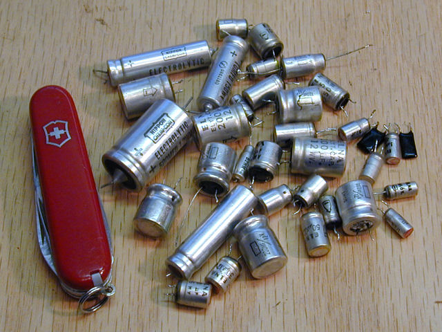
On we go, and the discard pile keeps growing. The Swiss army knife shows you how
small these electrolytics are. Their modern replacements are even tinier.
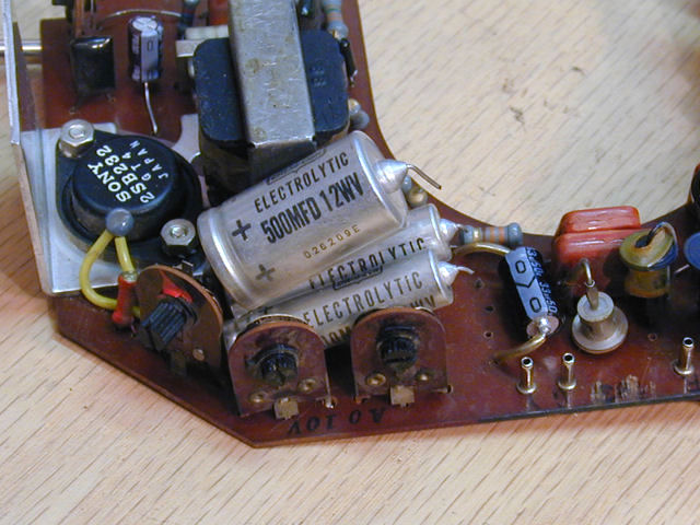
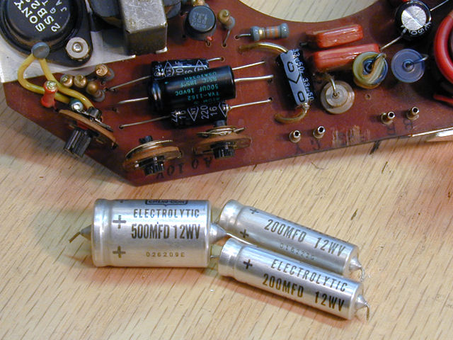
By the end, I had replaced more than 30 small electrolytics. I did not
replace the four big electrolytics in the power supply, however. My tester shows
they are in good shape and the power supply voltages are right on the money.
Final Thoughts
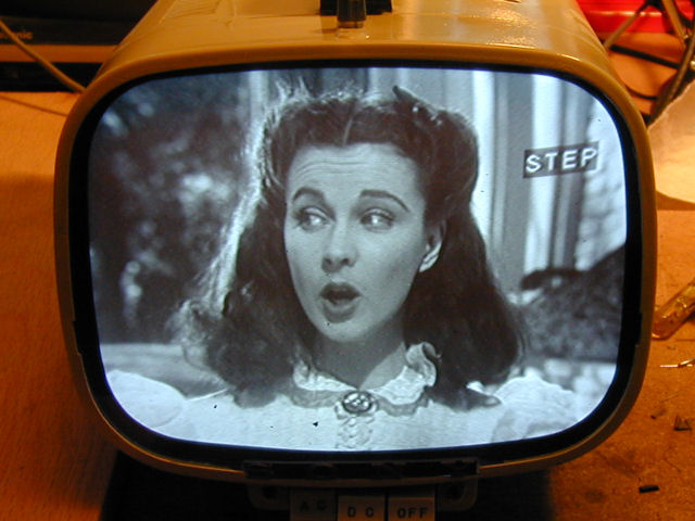
After reassembling the TV and making a few more adjustments, I was pretty
happy with this project. Here are a couple of unretouched screen shots
of the Sony at this stage.

It's interesting to compare the Sony 8-301W to the RCA 8-PT-7030, a
"miniature" tube TV from 1956.
The RCA was about as small as you could make a tube television at the time,
and, like the Sony, its electronics are carried on small subchassis
that wrap around the neck of the picture tube.


You can read more about that television in my
RCA 8-PT-7030 article.
Is the Sony 8-301W a great performer? Well, not really. Apart from substituting
transistors for tubes, the basic electronic design is conventional for 1961.
In a side-by-side comparison with the RCA 8-PT-7030, designed five years
earlier, you might find them pretty comparable in performance.
What set the Sony apart was the packaging, made possible by solid state components.
Few other companies offered such a compact, truly portable TV at the time, and this set helped blaze
a trail that mainstream TV makers would soon follow, into the transistor age where
"tummy TVs" and even hand-held sets would be commonplace.
Understood in that context, this little Sony was successful, despite certain
design restraints.
|