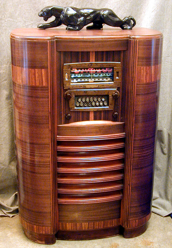
Stewart Warner Model 1865 Console Radio (1938)


This imposing model 1865 console was the top of the line for Stewart Warner in 1938.
With 14 tubes, a 15-station motorized tuner, and push-pull audio, it's hard to
ask more from a 1930s radio.
Description
These photos show the restored radio.
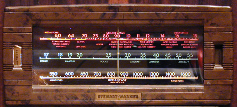
The 1865 is a three-band radio, covering the standard broadcast, police/aircraft, and shortwave bands.
I found this radio through craigslist and the seller told me,
"It doesn't work -- I'm not sure why." The original
owner lived on the Olympic Peninsula and the pushbuttons list the
following stations, some of which are still on the air:
- KEEN Seattle
- KFI Los Angeles
- KGH Spokane
- KIRO Seattle
- KJM Seattle
- KMO Tacoma
- KNX Los Angeles
- KOA Denver
- KOL Seattle
- KOMO Seattle
- KRSC Seattle
- KVI Tacoma
- KXA Seattle
Here's a list of the radio's 14 tubes and their functions:
|
Tube |
Type |
Function |
|
V1 |
6K7 |
RF amplifier |
|
V2 |
6L7 |
1st Detector |
|
V3 |
6C5 |
Oscillator |
|
V4 |
6J7 |
Control |
|
V5 |
6K7 |
1st IF Amplifier |
|
V6 |
6K7 |
2nd IF Amplifier |
|
V7 |
6H6 |
2nd Detector / AVC |
|
V8 |
6H6 |
Discriminator |
|
V9 |
6C5 |
1st Audio Amplifier |
|
V10 |
6C5 |
2nd Audio Amplifier |
|
V11 |
6V6 |
Audio Output |
|
V12 |
6V6 |
Audio Output |
|
V13 |
5W4 |
Power Rectifier |
|
V14 |
5W4 |
Power Rectifier |
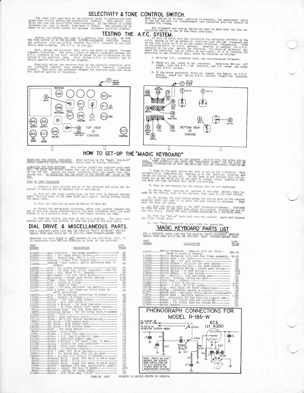
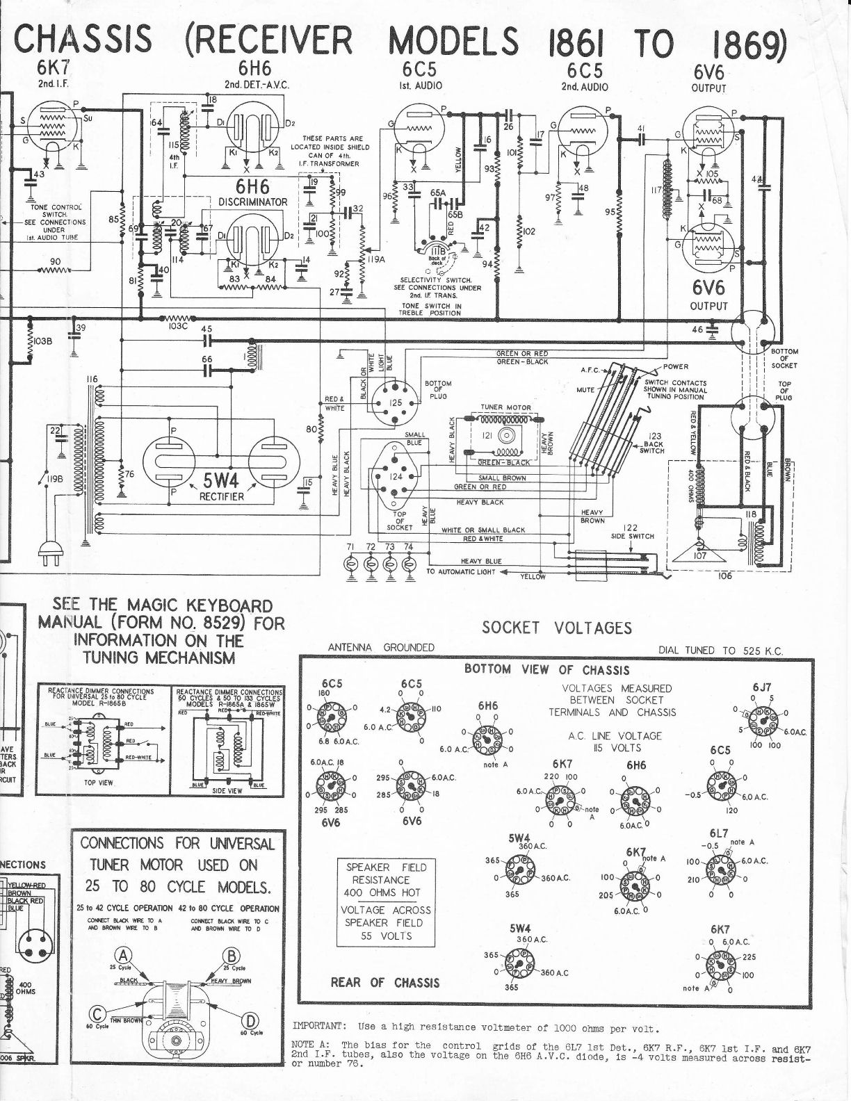
My 1865 has the R-186 chassis, which was used in a few 1938
Stewart Warner models. The basic Riders service manual consists of four pages. To save these documents
on your computer, right-click on each thumbnail and then choose Save Picture As...
The motorized tuner was used with at least two different chassis. Its manual is indexed
separately in Riders literature, under "Magic Keyboard."
The 1865's electronic design compares favorably with
other high-end 1930s radios, such as my Zenith 12-A-58.
In addition to push-pull audio, it has automatic frequency control (AFC), automatic
gain control (AGC), a tone control, and variable selectivity.
The AFC circuit helps to zero in on a station
when using the motorized tuner, a welcome addition since 1930s-vintage mechanized tuners
aren't terribly precise in the first place. The tone control is ganged with a selectivity
switch. In the Bass and Medium tone positions, the selectivity is sharp (narrow).
Choosing the Treble tone position switches in an additional IF stage and broadens
the tuning.
First Look
Here is the model 1865 cabinet as I found it, in excellent original condition.
Notice the louvered sound vents on the sides as well as the front.
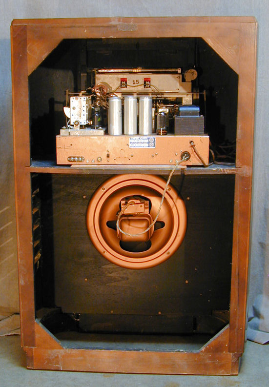
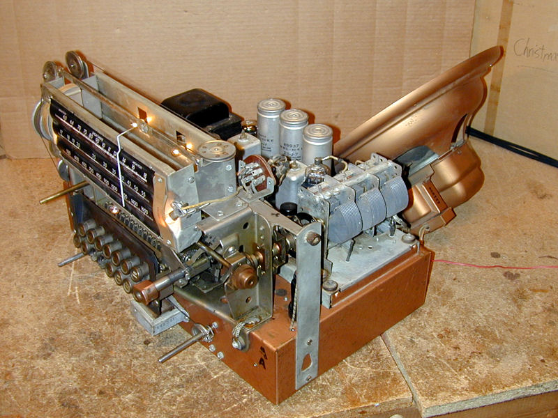
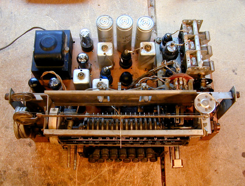
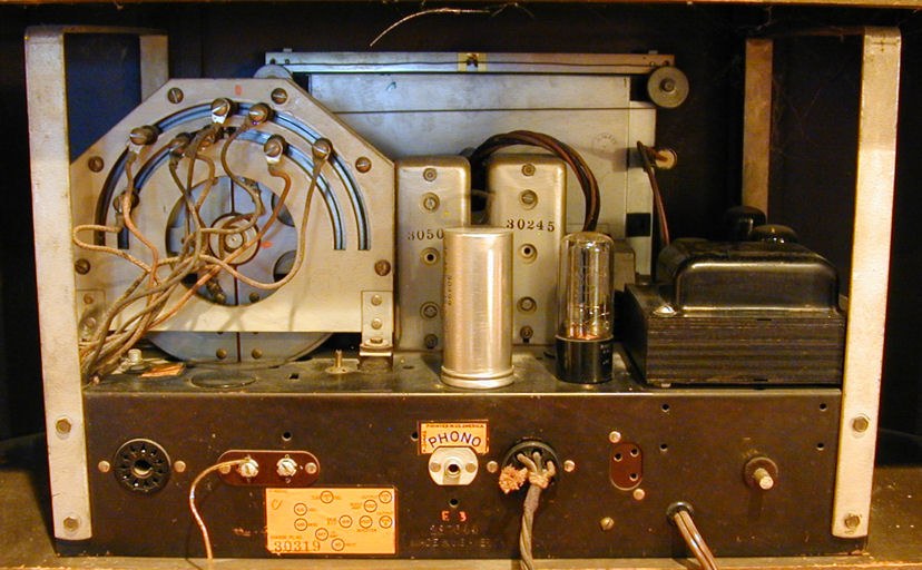
The next photo shows the unrestored chassis from above. Someone had recently
cleaned it up, although it had heavy dirt in the less accessible areas.
In that photo, the rear of the chassis contains the receiver and the front holds
the motorized tuner, dubbed the "Magic Keyboard" in Stewart Warner advertising.
From this angle you can see the 15 tuning pushbuttons and the row of 15 circular metal cams
behind them.
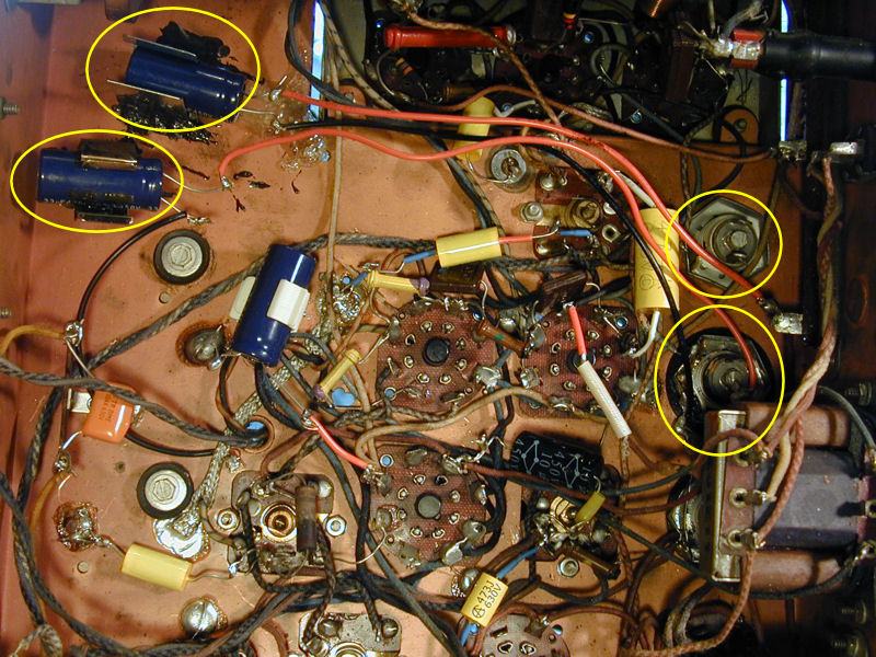
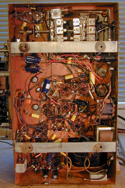
The next photo shows the chassis underside, which was both heartening and
dismaying. Someone had begun
to restore the electronics, replacing many of the paper and electrolytic
capacitors:
Alas, the restoration work was sloppy. Two of the electrolytic
capacitors had been relocated to the opposite side of the chassis, using
long, "lazy man" leads and sticking the cases on with gobs of hot glue.
In the next photo, I circled the relocated caps and the bottoms of the
metal cans in which the original electrolytics were installed.
If you read my capacitor replacement article, you'll
learn that there are various ways to replace capacitors inside cans. One is
to "restuff" the old cans, putting new caps inside. You can also
install the new caps under the chassis after disconnecting the old units.
When installing new caps under the chassis, you should keep them close
to the original location, and this photo shows why. The long red wires pass
next to the RF section of the radio (upper right, in the photo). The
current in those unshielded wires may create noisy interference, as I
learned when I made the same mistake as a rookie years ago.
There's room to locate these caps directly underneath the old cans,
so a first order of business will be to put them back there.
A Project Abandoned?
Further inspection revealed that the previous restorer hadn't
finished the job. Perhaps he gave up in frustration or simply lost interest.
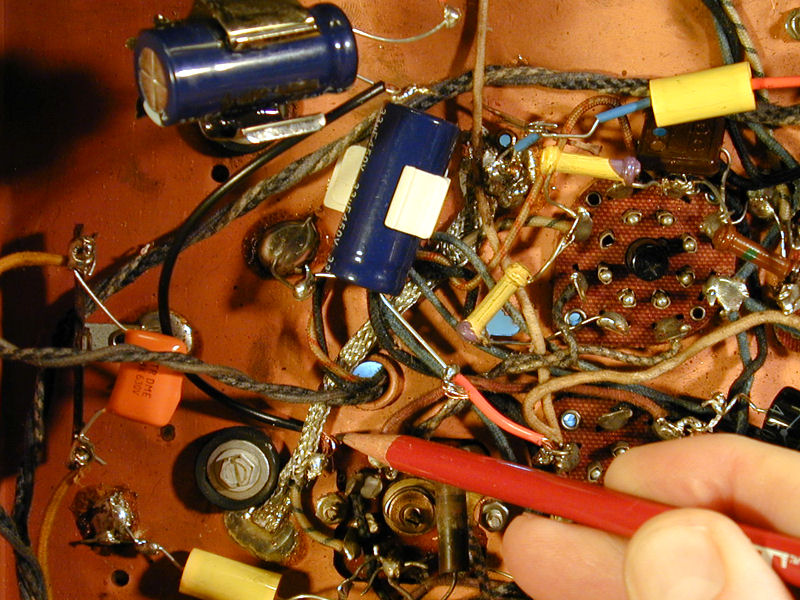
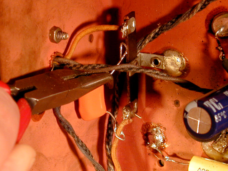
The following photo shows a wire that was disconnected and left
hanging loose. It leads to the speaker field coil, which acts as
a filter in the power supply. With the field coil out of commission,
the radio will have no B+ voltage and it can't possibly work,
although the tube filaments will glow.
My pliers is holding the original wire; tacked on its end are two
short pieces of wire, with different kinds of insulation. Who knows what this
guy was thinking? Perhaps he ran out of wire and was using
odd scraps. Or, possibly he wasn't sure where to
hook up the wire and was blindly trying different connections in the vicinity.
In the previous photo, I also circled some sloppy soldering work around the small
electrolytic capacitor. The best practice would be to remove
the old capacitor leads from the terminals and solder the
new leads there. Instead, the new leads were crudely attached to
pigtails of the original leads.
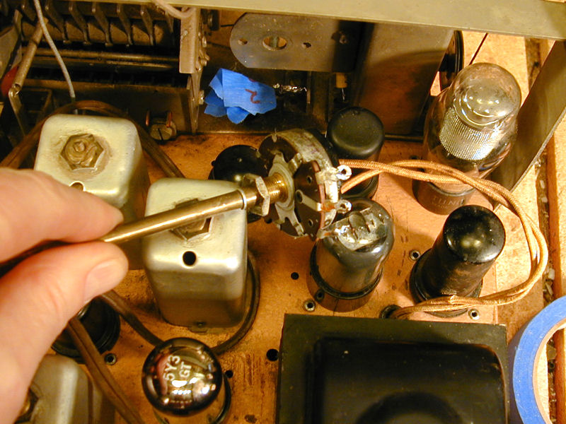
The closer I looked, the more problems I found. In this next photo,
I'm pointing to a cold solder joint. The intention was to connect the
negative lead of that electrolytic capacitor to chassis ground.

Not enough heat was used, and thus the new wire didn't stick to that
heavy braided ground strap. The capacitor lead is not electrically
connected to the strap. It merely hangs in midair next to it. No
circuit is made and the capacitor might as well not exist.
In the next photo, I have pulled out one of the "flying"
electrolytics, to move it back to a more sensible location.
The solder connections are sloppy and the
restorer tried to stick the cap to the chassis with a mess of hot glue.
Securing new capacitors is preferable to letting them dangle, but
hot glue is a bad choice. It adheres poorly and may fall off,
particularly if applied to a grimy surface.
A Bridge to No-No
Prior to relocating those caps, I noticed another electrolytic no-no. The positive
and negative leads for the new cap were wired in parallel with the original cap.

The new red lead connects to the original positive (center) terminal and
the black lead connects to the original ground. The electrolytic inside
that old can—very leaky or possibly shorted—is
still part of the circuit.
Do not permanently "bridge" or "jumper" a new capacitor
in parallel with an old one. That defeats the purpose of replacing the capacitor.
Take the old cap out of the circuit by disconnecting its positive lead.
Cold Solder Joints—Wrong!
The next photos show two more failed solder joints. Again, the intent was to
connect to chassis ground. Can you identify the problem?


Here, the restorer laid the capacitor leads next to screw heads
and simply globbed on some solder. This is a Bad Idea for three reasons:
- What if a future restorer needs to loosen those screws for some reason?
- There is no firm physical connection. The lead are not crimped or
otherwise secured to the bonding points.
- Not enough heat was used and thus the solder did not adhere. The
capacitor leads are really just lying next to the screw heads; any
slight vibration may make the connections intermittent, leading
to weird effects if the radio works at all.
To cure these problems, I removed the capacitors and installed new
ones using more sensible ground points.
By this time, I had lost faith in the previous restorer's work.
I decided to remove and reinstall all of the "new" caps.
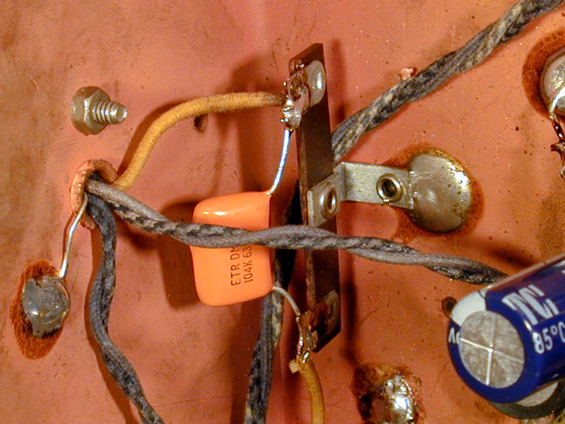
Here's another boo-boo that came to light a few minutes later.
In the next photo, I have unsoldered the orange cap's top connection, where the
capacitor lead had been loosely wound around the terminal and then
half covered with a solder blob. (That blob was removed by the time
I took the photo.)

As soon as I unsoldered the top connection, the bottom one fell
off completely! Again, there had never been a solid physical connection
and not enough heat was used to make a reliable solder joint.
I tested that orange cap to
make sure it was good and I also checked
the schematic to ensure that I had the right value in the right spot.
Then I installed the cap as should have been done in the first place.

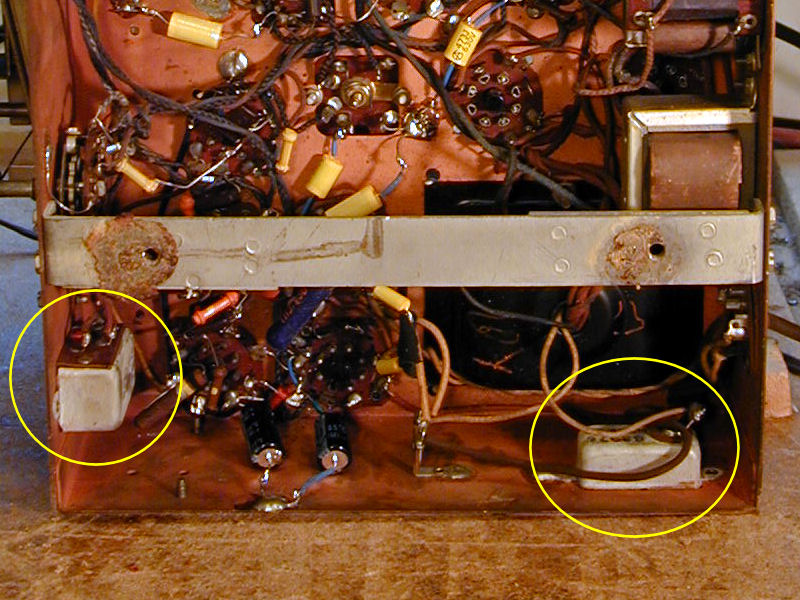
Replacing Bathtub Capacitors
This radio contains two "bathtub" style capacitors, so called because
they're encased in rectangular metal cases. They are circled in the following
photo:

The previous restorer had not touched them, possibly not recognizing what they were.
In military electronics, sometimes these caps are oil-filled and thus quite reliable.
In consumer radios, as I discovered when restoring my second
Scott 800-B, they are more often ordinary paper caps
in a metal shell, and usually unreliable.
The bathtub on the left contains two capacitors, used in the tone control circuit.
The one on the right, rated for 1,000 volts, acts as a line filter for the
AC power supply. I replaced both units with modern caps, disconnecting the
originals but leaving them in place.
You can read more about AC line bypass capacitors in this
article
from justradios.com.
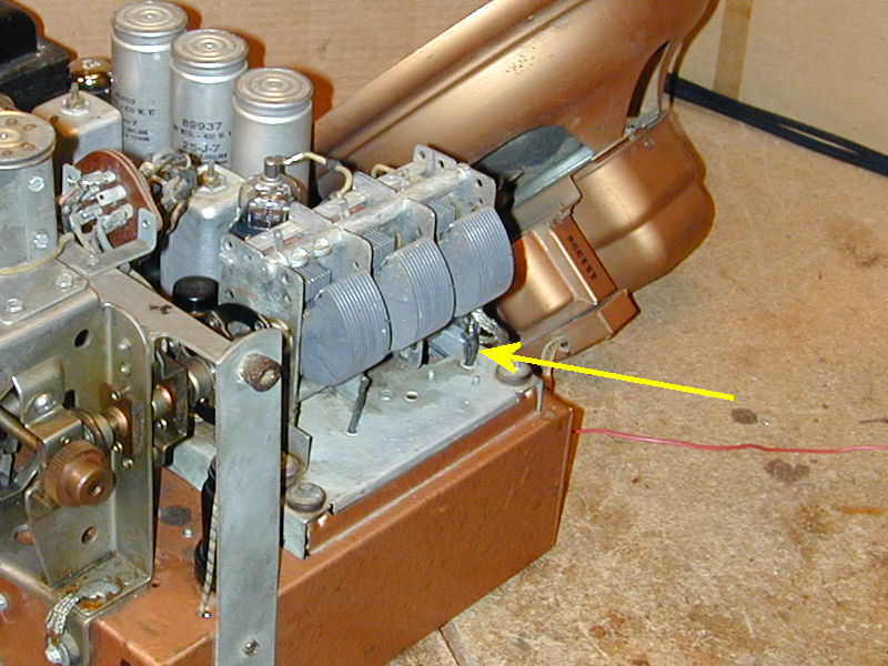
Disconnected RF Amplifier
Here's another mistake that would have been easy to overlook
had I not decided to redo everything.
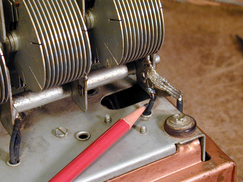
In the next photo, an arrow points to the trouble spot, where two
black insulated leads come up from the RF area through a hole in the
tuning capacitor base, to connect to the tuner frame.

To the casual eye, those leads look fine, but there's hidden
trouble inside one of them.
The area underneath that spot is crowded and not easily accessible. When
replacing a cap there, the restorer had been unable to reach both ends
of an old cap, so he snipped the nearest end and left the cap hanging from the
far end.
When I examined that old cap, I noticed that its remaining lead
came up through that hole to the tuner frame. By snipping that lead,
I was able to withdraw the old junk cap from the chassis.
After I did so, I noticed
that the second lead, right next to it, had already been snipped in
half! The soft cloth insulation had moved back together, so the cut
in the wire wouldn't have been evident unless you examined every inch
of the radio with a magnifying glass.
Perhaps the previous restorer cut the wrong lead by mistake
and forgot about it when he discovered that he couldn't pull
that old cap out.
Tracing things under the chassis, I discovered that the snipped lead
makes a connection to the grid of the 6K7 RF amplifier tube. At this stage,
I had finished the power supply and the radio was operational,
although I noticed that holding my hand near the tubes in the RF
section dramatically increased the signal. A weird effect, suggesting
that something might be amiss in that section.
Here is that disconnected lead, after I drew it back under the
chassis to attach a short extension.

And here is the same lead after I properly connected it on
top of the chassis.

After restoring that connection to the RF amplifier, the receiver portion
of the radio played normally at last. No more mysterious, Theremin-like changes
in volume when hands were waved near the radio.
Replacing a Flexible Resistor
Another damaged item, presumably snipped by mistake, appears below:
The component on top is a wirewound flexible resistor. When relocating the
filter capacitors in the power supply, I noticed that its insulation had
been cut all the way through. (The masked restorer strikes again!)
The wire inside, shown here partly uncoiled, was amazingly still intact.
I don't want my power supply to rely on half-ruined components. The specified
value for this resistor is 40 ohms. I'll replace it with two 82-ohm
resistors wired in parallel (82/2 = 41 and a difference of one ohm won't matter in this
application).
Flexible resistors are occasionally seen in radios from the 1920s-1940s, when
carbon composition resistors were not available in low-ohm values with
higher wattages. Their small size also made them useful in early auto radios.
There's no problem replacing a flexible resistor with a standard modern resistor
of the desired value as long as the wattage rating is sufficient. Flexibility was
incidental to the way these resistors were manufactured, not an essential
characteristic, and in fact some of them become quite brittle with age.
If you find a flexible resistor that's cut or broken, forget about soldering
it back together. The resistance wire inside is impossible to solder; that's
why the resistor's ends were crimped rather than soldered.
Cleaning Dendrites from the Volume Control
The radio was working, but its volume control was scratchy and
intermittent, a common ailment. On newer radios, the volume control
potentiometer often has an open slot next to its terminals, allowing you
to spray in a bit of DeOxit or similar electronic cleaner.
This older potentiometer has no such slot and must be opened up
for cleaning. Here, I have unsoldered the pot connections and removed the
control from the chassis front panel; there was no need to remove the
power connections in back, so I left them intact.

The case is easily removed by unbending five small metal tabs around
its perimeter:

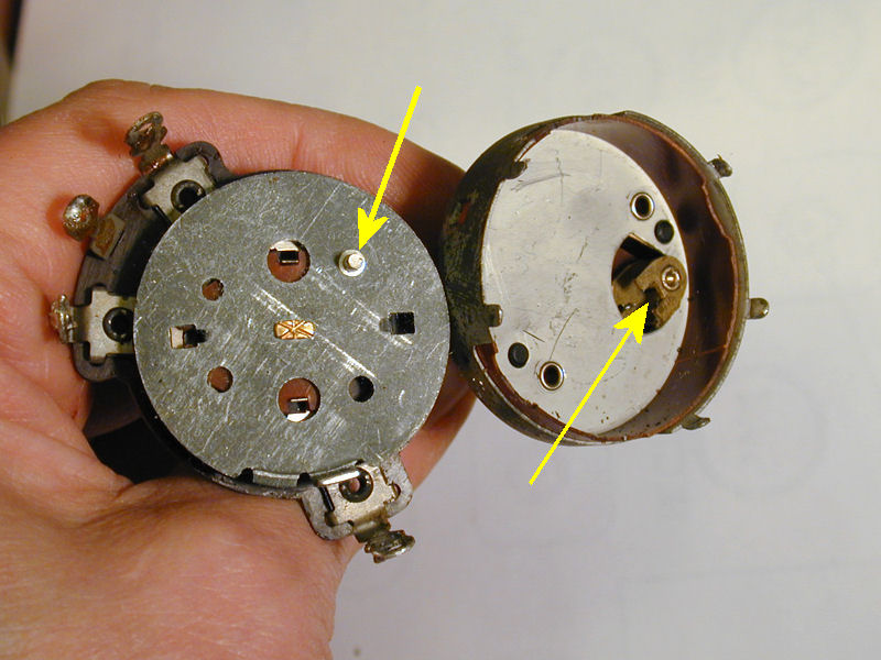
This pot includes an integral power switch. Notice the arrows in the
previous photo. One points to a little metal pin in the rotating
portion of the potentiometer. This engages a small slotted cam,
shown by the second arrow, which activates the switch.
When reassembling the control, you need to make sure that this pin
mates with the cam.
In some instances, a light cleaning with DeOxit is all that's needed to
remove gunk inside a potentiometer. This pot
has a different problem, however. Look at the tiny metal "dendrites"
growing down from the upper plate in the following photo. The intermittency
was caused by short circuits from these metal hairs.
Dendrites form on plated metals
in the presence of an electrical field and moisture.
In a process similar to electroplating, metal ions migrate from the plated material
and grow into hair like shapes.
Some people mistakenly call these "tin whiskers," but whiskers are a
different phenomenon, as noted in a NASA
paper that distinguishes the two.
Whatever you call them, they're simple to remove, using compressed air, a tiny brush, and your favorite
electronic cleaner. After I reassembled the control, it operated smoothly
with no scratchiness or intermittence.
Dendrites can form outside a control case as well as inside. Occasionally,
strange intermittency problems occur when a dendrite creates a short circuit
from a control case or terminal to the chassis or another component.
Aligning the Receiver
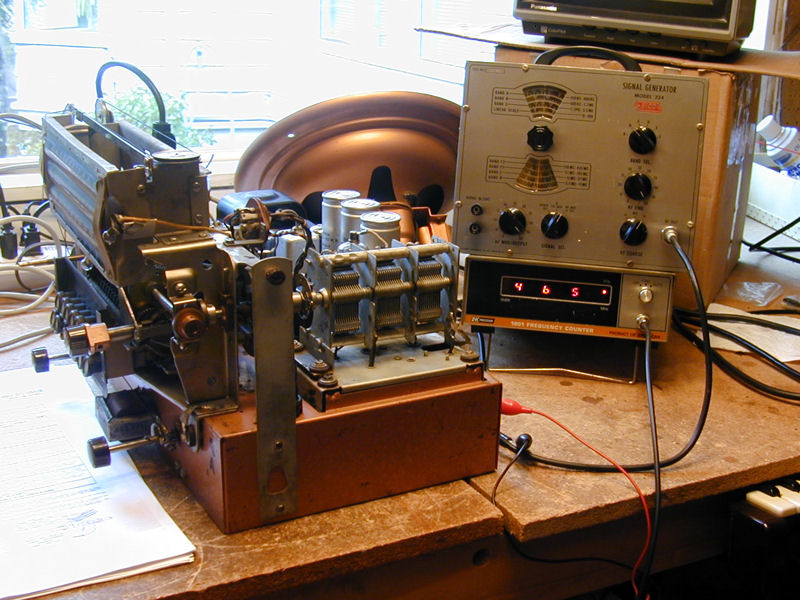
At last, the receiver portion of the radio was working normally. Before turning
to the motorized tuner, let's check the radio's alignment. In this photo, I
have powered up my trusty
EICO 324 signal generator, using my B & K Precision
1801 frequency counter to double-check its setting.

The frequency counter shows that the generator is set exactly to 465 KHz,
the 1865's IF frequency. After I finished aligning the radio, it was
receiving nicely on all bands.
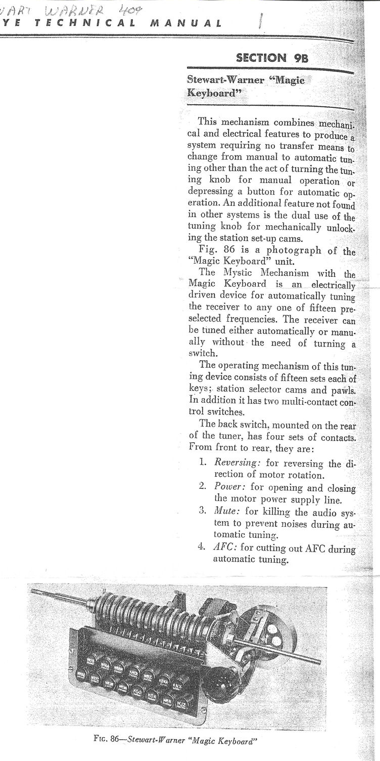
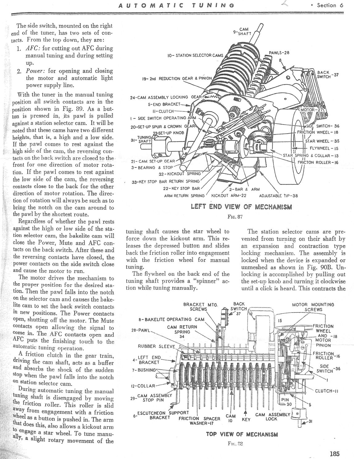
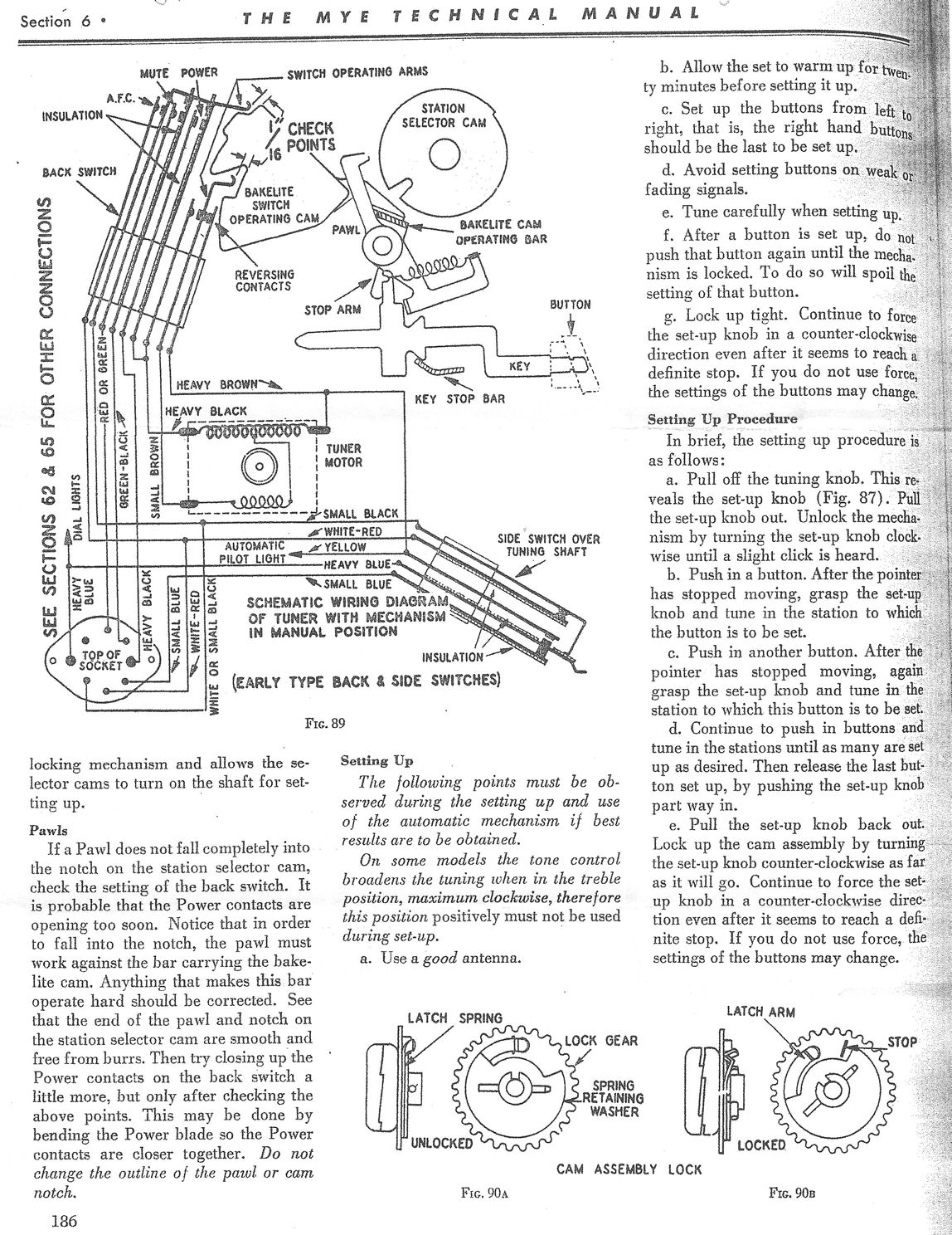
The "Magic Keyboard" Motorized Tuner
The motorized tuner on my Stewart Warner 1865 is a complex electromechanical
gizmo, with gears, cams, pawls, springs, drive wheels, switches, lights, levers,
buttons, pulleys, shock-absorbing clutch, flywheel, and a reversible motor.
This diagram shows the main assembly, which
Stewart Warner called the "Mystic Mechanism:"

With 14 buttons in two rows, the "Magic Keyboard" resembles a typewriter
keyboard and the similarity was probably not accidental. These diagrams from
the service manual provide more details:


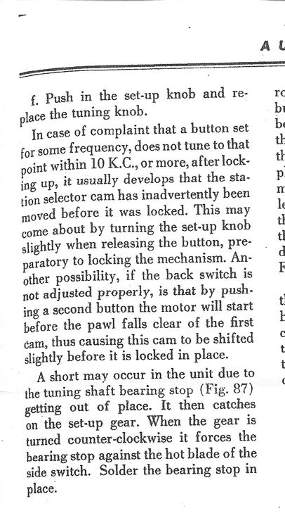
The Riders manual, strangely, doesn't provide a step-by-step explanation of how
the tuner works. From a fellow collector in Canada, however, I got a copy of
a Mye Technical Manual that describes its operation
(Page 1,
Page 2,
Page 3,
Page 4).
With that description in hand, the preceding diagrams will make a lot more sense.
Motorized vs. Electronic Auto-Tuning
In a motorized tuning system, an electric motor moves the whole tuning mechanism—tuning capacitor, dial pointer,
and so on—to a preselected station. In place of your fingers, a motor provides the driving force.
Motorized tuners make sense intuitively, but in practice these complex gizmos were
subject to breakdowns and also very expensive.
Electronic auto-tuning was much more common. This kind of system was employed in my
Zenith 12-S-471 and many other radios. In an electronic system,
the tuning capacitor doesn't move when you push a preset station button. Instead, the button switches out
the main (variable) tuner and switches in a little circuit—perhaps only a coil and trimmer capacitor—that
is pre-tuned to a single station.
Inaccuracy was another bugaboo of the motorized tuner. Over time, the tuner's many parts may
move out of adjustment, run out of lubricant, or simply wear out. That's the nature of the beast.
In the R-186 chassis, Stewart Warner added AFC (automatic frequency control) to compensate for the motorized
tuner's inherent inaccuracy. In automatic mode, the motor gets you pretty close to the desired station and
then the AFC kicks in to "touch up" the tuning as needed.
With almost no moving parts, electronic auto-tuners were both accurate and reliable, and
vastly cheaper than motorized systems. For the well-heeled buyer, however, there
was nothing quite as sexy as a motorized tuner, and so they were offered in a small
number of high-end radios.
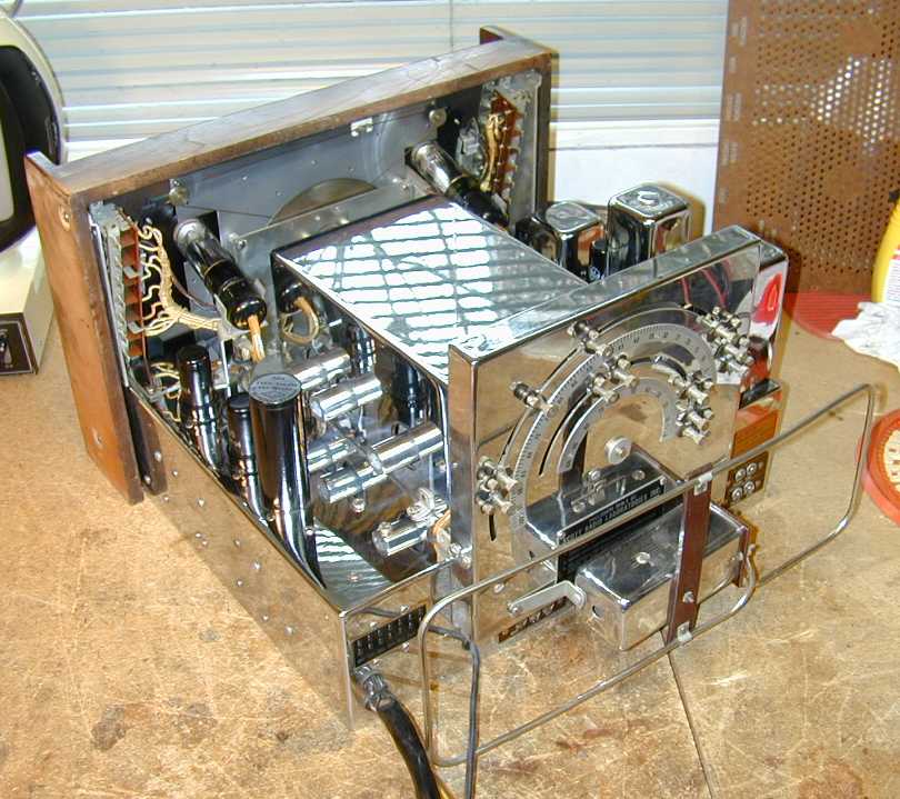
Other radios in my collection with motorized tuners include the
Stromberg-Carlson 440M
and the Scott 800B6. In these two photos,
showing the Stromberg-Carlson and Scott, respectively, the large
semicircular assembly forms the heart of the automatic tuner.

Servicing the Motorized Tuner
When I got my model 1865, the motorized tuner didn't work, but then nothing else did, either!
After reading the tuner service manual, I decided to restore the receiver first and worry
about the tuner later.
Eventually, I reached the stage where there was nothing left to fix except the
Mystic Mechanism.
The first order of business was to inspect, clean, and lubricate everything.
Much of the gear seemed operable, but nothing happened when I pushed a button.
The obvious culprits were the switch contacts. Referring back to the diagrams, you
can see that the mechanism has two groups of switches, the Back Switch and the
Side Switch. These control everything—supplying power to the motor and
the Automatic pilot lamp, muting the audio while the motor is turning the
mechanism, reversing the motor direction as needed, and activating the AFC
when a station has been approximately reached.
I began with what I'd normally consider a good cleaning, using
DeOxit and running strips of thin cardboard between the contacts under
slight pressure. No go.
To make a long story short, I cleaned the switch contacts again and again, over
a period of two days, using every method and type of cleaner I could lay my
hands on. Eventually, I got a few sparks from the power switch and then, as
I exercised all of the switches, they all started making normal contact. Sheesh!
I took the following brief video as soon as I got the tuner working:
The preset buttons were not set to current stations, so nothing except static
was heard, but at least you can see the tuner zip back and forth. At that time, I
was still powering the radio at reduced voltage on a variac. Later on, after I did
some more lubrication and ran it at normal line voltage, the auto-tuner was both quieter and faster.
I haven't tried to set up the auto-tuner for current radio stations.
The AM radio programming in this area is so awful that I'd be hard pressed to
come up with three favorite stations, much less fifteen. And, while I like
my motorized tuners to be functional, I never use them except to demonstrate
to visitors.
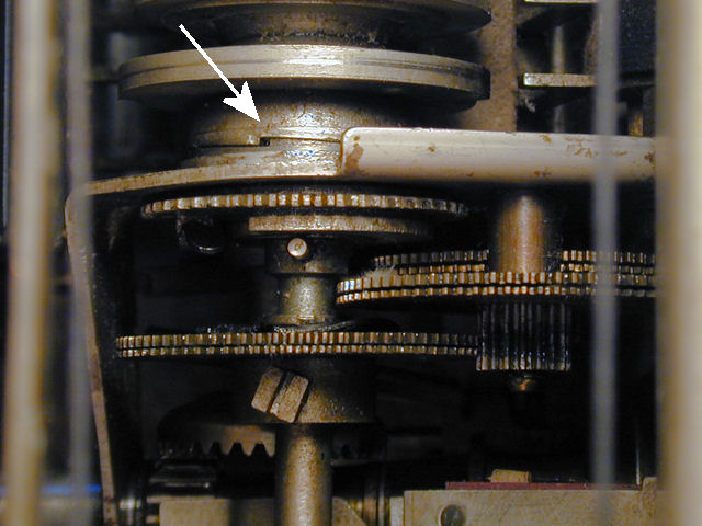
One balky part makes setting the stations tricky. In the next photo, I
arrow points to the "cam assembly lock," which I carefully
cleaned and lubricated:

To set the stations, you need to pull out the special setup knob, turn it all the way
to the end of its travel, and then turn it really hard to release the lock.
When setup is finished, you turn it in the opposite direction. I finally got the
lock to partly release, but only by gripping the knob with a big plier. So much force
was needed, that I was worried about stripping the teeth off the tuner
mechanism's bell-shaped gear. Since I don't care about the station settings
in the first place, I decided to quit while I was ahead rather than risk ruining
that "unobtanium" part.
Cosmetic Restoration
This radio's cabinet was in fine original condition and only needed minor
touch-ups here and there.
My radio was missing two large wooden knobs and two pushbutton covers.
I was able to obtain knobs from Mike Koste.
The button covers are a little problematical. They are constructed much
like old-fashioned typewriter key covers: thin metal circlets with a transparent
center, under which you place a paper with the station's call letters.
I don't have metalworking equipment, so fabricating reproductions is not
practical. Perhaps I'll look in second-hand stores for old typewriter
keys. Standard letter keys are too small, but the Shift keys are larger,
and possibly a couple of them could be adapted to fit.
With those little details, the restoration will be complete. Meanwhile,
the radio looks and sounds pretty great!
|


