|

Direct Video Adapter for RCA CT-100 Television


This article presents information about building a video adapter for the
RCA CT-100 color TV.
The adapter optimizes picture quality by injecting the signal directly at
the first video amplifier, thus bypassing the CT-100's tuner and IF circuits.
The adapter requires no hardwired connections to the CT-100 chassis and it
has a switch to toggle between direct input and the native signal from the antenna.
If you'd like to consult a CT-100 schematic in the course of reading this article,
you will find full service manuals in my article about CT-100 television design.
1956 RCA Design
This adapter is based on plans from a 1956 article in RCA Broadcast News.
(Thanks to John Folsom for providing scans of the article.)
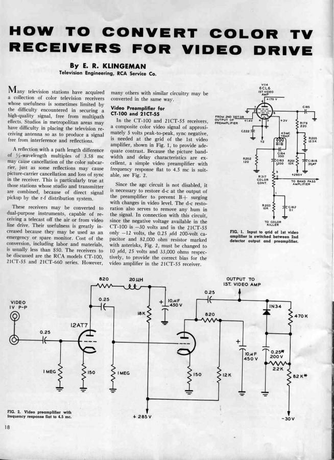
The article states that the CT-100 requires a video signal of approximately
5 volts peak-to-peak at the grid of its first video amplifier. Since a standard
video signal provides about 1 volt, the adapter includes a preamplifier
to boost the signal level.
The adapter needs two power sources: B+ voltage, obtained by tapping one
terminal of the contrast control, and negative bias voltage, available
from the -30V source inside the low-voltage supply cage. Both sources
are accessible above the chassis.
Improved Plug 'n Play Design
At the 2009 Early Television Foundation conference,
Pete Deksnis presented a revised adapter design. Click the following icon to read his
presentation, including the schematic and other details.
Rather than tap the TV's -30V source, Pete's adapter uses a voltage doubler
to produce bias voltage from the 6.3VAC filament source. (Note that -17V from
the doubler requires the 33K and 20K resistor combination to correctly bias
the DC restorer.) This eliminates one of the external connections.
Pete's design also modified four component values to improve the adapter's low-frequency response.
Among other things, this adapter was used in a demonstration
of a rebuilt 15GP22 CRT at the 2010 ETF convention.
Building a CT-100 Video Adapter
Back in 2010, I built an adapter as described in the Broadcast News article.
It worked, but then I got involved with other projects and it was shelved for a while.
In 2013, when I was building an A/V adapter
for a black and white TV, I ran across a reference to Pete's improved design. When I
contacted Pete, he gave permission to publish the above conference presentation,
and I decided to update my adapter.
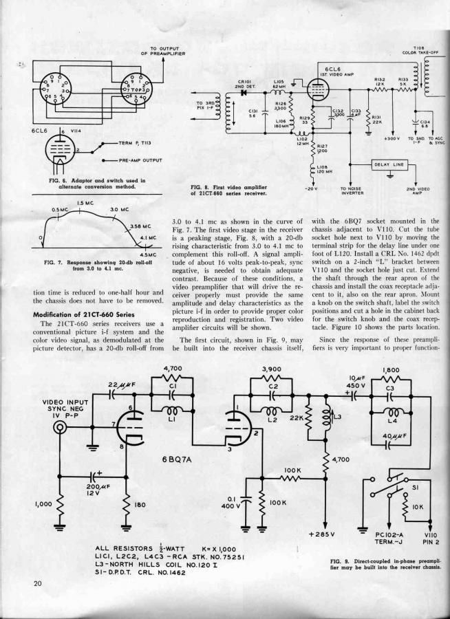
My old adapter had followed the original RCA design closely. For installation,
I chose the method shown in Figure 6 of the Broadcast News article, using a
switch and a 9-pin socket and base that allow you to plug the 6CL6 video amp tube
into the adapter and toggle the external signal in or out.
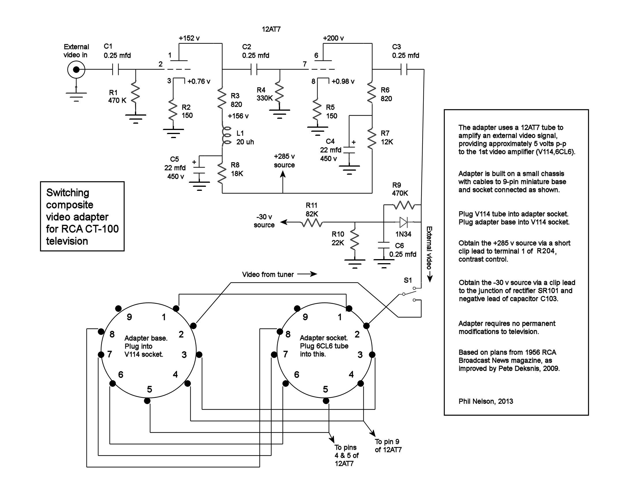
Pete's improvement called for changing two capacitors and two resistors in my adapter,
which worked better than ever after the update. Here is the schematic as modified:
The changed components are R1 and R4 (both originally specified as 1 megohm) and
C4 and C5 (originally specified as 10 mfd).
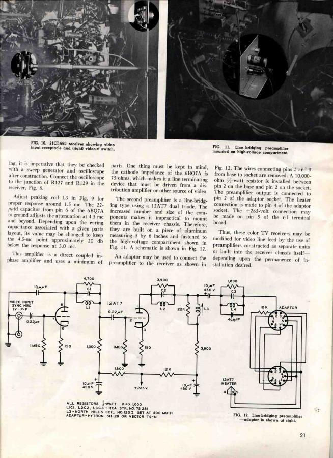
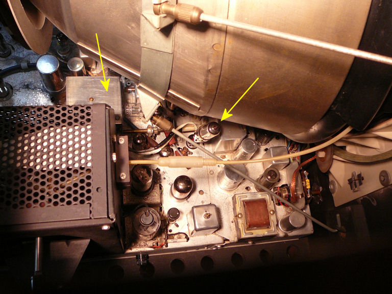
The next photos show my adapter. The 1956 article contemplated hanging the adapter
from the side of the high-voltage cage cover. Mine sits on the chassis
next to the cage, with a slot to clear the shaft of the contrast control.

You can also see the clip connectors used to tap into the CT-100's +285V and -30V power sources.
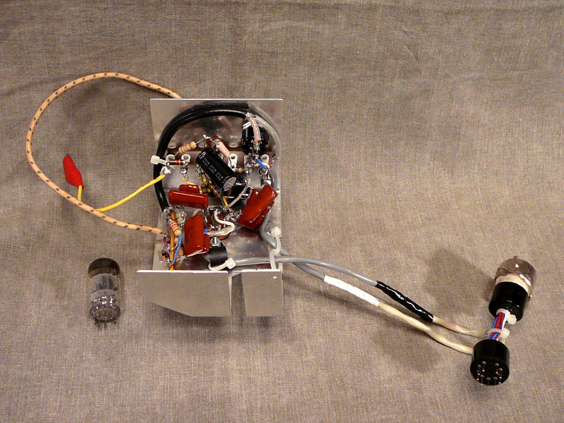
When installed, the adapter's 9-pin base plugs into the 6CL6 socket and
the 6CL6 tube plugs into the adapter socket. In this photo the arrows point to
the top of the adapter frame and to the 6CL6 video amplifier tube standing up on its short
extension:

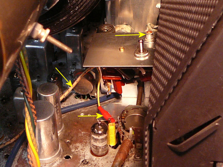
In the next photo, we are peering into the rear of the chassis, past
the CRT neck and HV cage. The yellow lead is clipped to the
contrast control terminal and the cloth insulated lead travels to
the -30V source off-camera at left. The jack on top of the adapter frame is where we'll
plug in a video cable.

Using the Adapter
When I built an A/V adapter for another (black and white) television, it was easy
to inject audio as well as video, although that required pulling the chassis to
access the audio connections underneath.
When I asked Pete about this, he said that he usually feeds the audio through the
antenna when using his video adapter. You could get optimal sound by injecting audio
directly, but even a less-than-perfect tuner and IF will pass audio well.
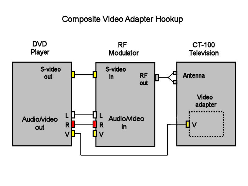
Here's a basic hookup that gives me video through the adapter and audio through the antenna:
The RF modulator that I'm using—an inexpensive Radio Shack number—wasn't happy when
I simply moved the composite video cable from the modulator input to the adapter. (The video
came through, but the audio dropped out.) After I added an S-video cable from the
DVD player to modulator, I had audio and video both ways.
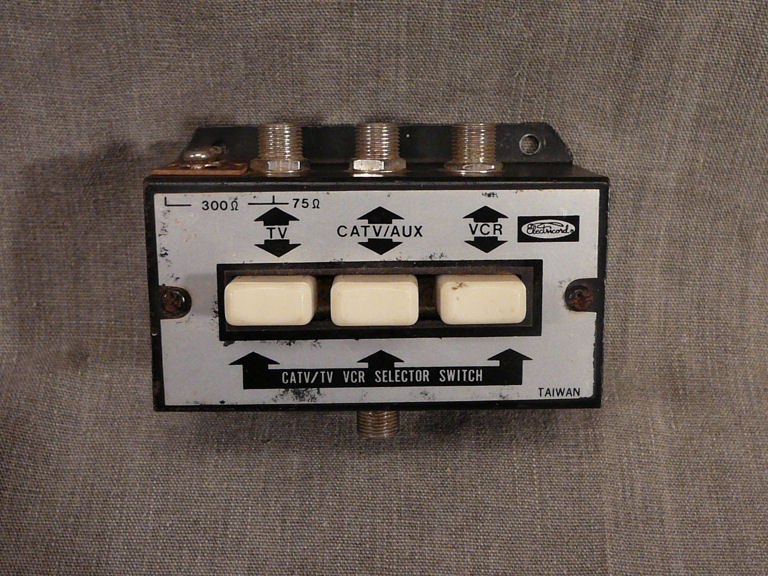
For daily use, I added a switch at the CT-100's antenna, using this old thrift store
item as an A-B switch:

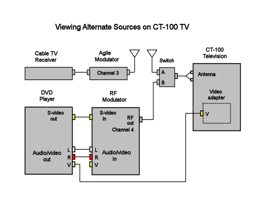
The following diagram shows how I have set up my CT-100 to view alternate sources,
either playing a DVD with the direct video adapter or watching cable television
via the antenna:
To watch cable programming broadcast through my home TV transmitter
on Channel 3, I switch the antenna to source A (for both audio and video), switch the
video adapter to Internal, and choose Channel 3 on the television. To watch a DVD
using direct video input, I switch the antenna to B (for audio), switch the
video adapter to External, and choose Channel 4 on the television. Of course, many
other hookups are possible.
Pete pointed out that the video adapter interrupts the CT-100's AGC loop. After a little
experimentation, I found it works best to set the AGC control for optimum picture and
sound with the antenna input. That setting also works fine with direct video input (in
direct mode, the AGC setting is much less critical).
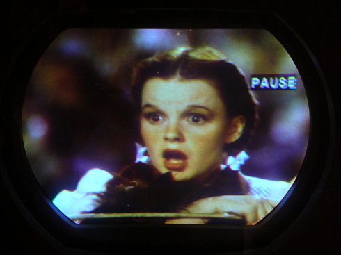
Here's a quick snapshot to show the adapter in action:
(Yes, I see that the edge convergence is less than perfect. Many things got twiddled in the
course of solving a color sync issue way back when, and my CT-100 hadn't gotten
much attention since then.)
Now that I've seen what a great picture this set is capable of,
I'll be motivated to redo the entire color setup. After that, I may
take some "Pepsi challenge" photos to compare the picture quality
between direct video and normal reception.
Final Thoughts
If I were to build a new adapter from scratch, I'd follow Pete's elegant plug 'n play
design, and I'd make it an A/V adapter that injects audio as well as video.
Sure, bypassing the tuner and IF is cheating in a sense, but if
you're going to bypass at all, why not go whole hog? The adapter has a switch, so
I can still use the television as designed, simply by flipping the toggle.
If you build a CT-100 adapter or you have any further thoughts,
send me an email.
Phil Nelson
This electronic construction project, including all descriptions, diagrams, photos, and the underlying electronic design, is published here for the noncommercial use of radio hobbyists. You may print and reproduce these project instructions for your personal use. Commercial use of this material is not authorized.
|