|

Powering Your Antique Battery Radio
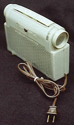
Many antique radios run on batteries. These include tube portables , such as the Zenith model K-401 shown below, and "farm" radios, which were used in rural areas where there was no other source of electrical power.
This article gives you some history on battery use in old radios and advice on how to power them with modern batteries. It also gives plans for two inexpensive battery eliminators that you can build, with additional suggestions and technical data.
History of Battery Development
All early radios used batteries—as many as three batteries in the earliest sets. These batteries were known as A, B, and C. Radio engineers soon designed circuits to eliminate the C battery in a typical radio circuit. That left two battery supplies, A and B.
Rechargeable nickel-cadmium battery packs didn't exist in the "good old"
days, but some owners of "farm" radios used rechargeable lead
acid batteries, of the type still used in cars. Often, the only available
battery was taken from the family truck or car. When the battery ran down,
the farmer could simply hook up the battery to a generator and recharge it.
For the portable radio user, the price of mobility was a large, heavy,
disposable zinc-carbon power pack.
Early battery sets had several drawbacks. A dead battery could leave you radio-less in the middle of a crucial broadcast. Lead acid cells could leak acid, which might drip out of the radio cabinet onto your lovely Persian rug. Worst of all, if you accidentally reversed the A and B battery connectors, you could fry your radio's precious tubes.
Recognizing these problems, radio makers, many of which also made and sold tubes, sought to develop battery-less radio sets. Perhaps more radio tubes could do part of the job of expensive disposable batteries.
Radio tubes offer two important features. A tube can act as an amplifier,
taking a tiny voltage, such as an incoming radio wave, and increasing it
sufficiently to be heard through a headphone or speaker. A tube also can
act as a diode, which changes alternating current (AC) into a series of
half-cycle pulses that approximate the direct current (DC) that flows from
a battery.
Alternating current became increasingly available in homes during the 1920s, and radio engineers soon developed new radio tubes, called rectifiers, which could convert AC to DC. Soon, the stores were filled with battery-less radio sets using rectifier tubes. Everyone loved these new radios, except the battery manufacturers.
Having recently lost their bid to develop electric cars for the auto industry, battery makers now faced another blow: the loss of the radio industry. Many manufacturers closed their doors. Others developed smaller zinc-carbon batteries to replace bulky lead acid cells. Smaller batteries made possible small hand-held flashlights, which became very popular. Everyone wanted one or two or three, and these new products used lots of batteries—flashlight batteries.
Soon, consumers were carrying flashlights to places where there was no electricity, such as a cabin in the woods or a treehouse in the backyard. When you got to such a destination, wouldn't it be nice to have a radio to listen to?
Radio manufacturers seized the opportunity to offer something new. On the technical side, new radio tubes were developed to operate on the lower voltages supplied by flashlight batteries. On the marketing side, stylists developed radios with a new appearance.
Many new portables were disguised as expensive luggage. Their cabinets were made of lightweight wood covered with colorful airplane cloth (see RCA 94BP1), canvas, leather, or leatherette (see TransOceanics). Others were made of metal, Bakelite, and other early plastics (see Tube Portables).
The results were spectacular. The new portable radios sold in great numbers, and many still exist today. To use a battery radio in the 1990s, of course, you need the right batteries, or some substitute for them.
Using Modern Batteries in Old Radios
Battery radios offer great bargains for modern collectors. Not everyone knows how to power them, so they often sell for less than their AC-powered counterparts. Many of them are still in amazingly good shape. Daunted by the expense and inconvenience of using large, costly, non-reusable batteries, many owners simply stored their radios in a closet or shelf, where they remained untouched for years.
Some times, you may find an original battery still inside an old radio. Although nice for display purposes, these batteries are invariably dead and cannot be recharged. This website shows a few examples of such old batteries.
Battery radios that use two batteries (A and B) rather than three usually have polarized connectors, which prevented users from making wrong connections. If you are powering such a radio with some other source, such as the battery eliminator described below, you may be fastening wires to the connector with alligator clips, or bypassing the connector entirely.
Understanding A and B
To avoid costly mistakes, work slowly and carefully when you power up a battery radio. It will help to understand a little about the difference between the A and B power supplies.
- The A supply provides low-voltage DC to heat the filaments inside the radio tubes. It can be as low as 1.5 volts.
- The B supply provides higher-voltage DC for the "plate" circuits of the radio. The B supply can be 22.5, 45, 67.5, or 90 volts.
Why the difference in voltage between A and B? The answer has to do with the way that tubes work.
When you connect the A battery, the filament of the tube is heated to
release negatively charged electrons. When the B battery is connected, it
puts a positive charge on the plate of the tube. Electrons travel through
the partial vacuum inside the tube, flowing from the filament to the
positively charged plate. Many tubes also have small structures, known as
grids, between the filament and the plate. The grid regulates the number of
electrons that strike the plate.
Thus, every radio tube must be supplied with two different voltages (A and
B), and most will need three (A, B, and C). The A voltage heats the
filament to release electrons. The B voltage gives the plate a positive
charge to attract electrons from the filament.
The C voltage lets the grid
regulate the flow of electrons from filament to plate. As noted earlier,
modern radio designs eliminate the need for a separate C battery. If your
antique radio requires a C battery, check out the building plans near the
end of this article.
The voltage required from the B battery depends on the size of the charge needed at the tube's plate. Circuit designers calculate the needed charge using formulas such as Ohm's law (V=I*R), which says that voltage pressure is equal to the product of the flow of electrons through a known amount of resistance.
The plate current of a tube is very small compared to its filament current.
That is why filament (A) batteries, despite their lower voltage ratings,
often are much larger than plate (B) batteries, which have higher voltage
ratings. As a result, the filament batteries are exhausted more frequently
than the plate batteries. If your battery portable quits working, try
replacing the A battery before the B battery.
Connecting an A Battery
Many battery-powered tube radios require only 1.5 volts for the A supply, which you can provide with ordinary 1.5-volt "D" cells (flashlight batteries). If more than 1.5 volts are needed, connect additional batteries in series. Two 1.5-volt batteries in series will provide 3 volts DC, and so on. Radio Shack and other retailers, sell inexpensive holders that simplify connecting multiple batteries.
If onboard space limits the size of your A battery, consider using smaller-sized "C" cells rather than "D" cells. "AA" cells can also be used, but you may be disappointed with their short operating life. They are too small to power a radio for more than a short test period.
Connecting a B Battery
Although you can still buy manufactured B batteries (see our Parts page), these large cells have several drawbacks. They are expensive, costing anywhere from $10 to $30 each, and they don't last long. Under normal conditions, you may get no more than four or five hours of service from a standard zinc-carbon B battery. Batteries also contain hazardous, corrosive chemicals that make safe disposal an environmental issue.
If you connect a new B battery to your radio, be sure to make the right positive and negative connections, especially if the battery terminals don't match the connectors in your radio.
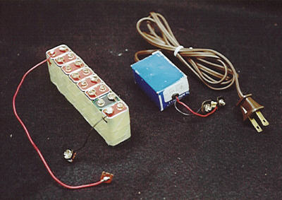
A simple substitute for the traditional 90-volt B supply is to connect ten 9-volt number 216 "transistor radio" batteries in series. These batteries are small and easily obtainable. Their low-current output is quite suitable for B supply applications. If purchased in bulk quantities, their operating cost can be less than buying two 45-volt batteries or one 90-volt battery. The first photo in the next section shows such a homebrew battery pack, with several 9-volt batteries taped together. Although simple to construct, this battery supply will not last long and you will still have the problem of disposal.
Building a B Battery Eliminator
For about $10, you can build a simple circuit that converts 120-volt AC household current into the DC current needed for a battery radio's B supply. This battery eliminator is friendlier to the environment than disposable cells and its cost of operation will be next to nothing. It is designed by Walter Heskes, who has contributed several radio projects and restoration articles to this website (see Building). Walter also supplied
all of the technical information for this article.


The following schematic diagram shows the circuit.
All needed parts are available from Antique Electronic Supply. If you order everything from AES, substitute a type 1N4005 diode for D1. AES doesn't offer a type 1N4003, but the 1N4005 works exactly the same. Or, you can buy a pack of several type 1N4003 diodes from Radio Shack for about one dollar.
The next photo shows the completed B power supply on the right and a homebrew battery pack on the left. As you can see, the B supply takes up less space, allowing it to fit inside many portable radios. (Click the thumbnail image to see a larger view.)
Parts placement for this simple circuit is not critical. Caution: this project requires basic electronic construction skills. Any project involving 120-volt household current holds the potential for dangerous shocks. If you are not comfortable in your ability to safely build this project, find a mentor who has the necessary expertise.
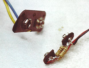
In addition to the parts listed in the schematic, you'll need an AC line cord and some kind of connectors to connect the supply to your radio's B battery terminals. As the next photo shows, you can salvage connectors from an expired battery. (Use extreme caution if you dismantle a battery. Battery chemicals can be toxic!)
If you don't have an expired battery with the right size connectors, you'll need to improvise some other sort of connectors, such as alligator clips. Using color-coded leads, red for positive (B+) and black for negative (B-), will help prevent confusion when connecting the supply to your radio. If you're in doubt about where to clip these leads, you'll need to get a copy of the schematic diagram for your radio. Antique Electronic Supply also sells schematics.
The following detail shows how Walter used the circuit's bleeder resistors to create the structure for his connector. On the right is the new connector and on the left is the original, matching connector from the radio.
Since the circuit connects to your house current, you should build it in a small plastic box or other suitable enclosure to eliminate shock hazards. Walter's prototype is enclosed in a small cardboard box that once held a Clarostat variable potentiometer. Ideally, your enclosure should be small enough that it, as well as the line cord, can be contained in the space where the original battery was stowed.
For additional protection while the battery eliminator is in use,
you can power it through an isolation transformer. Suitable transformers are available
from Antique Electronic Supply and other suppliers.
You'll need to find or make a small hole somewhere in the radio cabinet for
the power cord. Many battery-only portables have no such opening. If your
radio has the common "clamshell" design, one solution is to file a small
rectangular notch in the bottom of the rear cabinet piece, just large
enough to fit the line cord. The next photo shows the notch in Walter's radio.
This is a one-way modification, so keep in
mind that making any changes in a collectible radio may diminish its future
collector value to purists. Some collectors might appreciate the extra
convenience, of course. If you don't want to make an opening, you can
simply leave the cabinet open wide enough to admit the cord when in use,
and close it up at other times.
Using Your Battery Eliminator
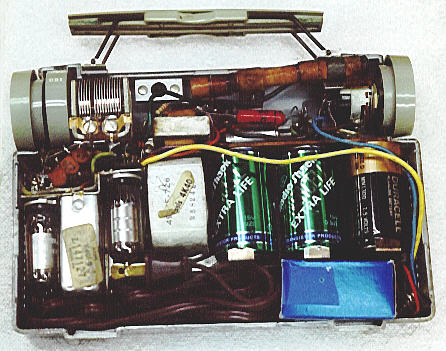
The next photo shows the completed battery eliminator tucked into the old battery compartment in Walter's radio. The B supply is housed in the small blue box at lower right. It's a snug fit, but the battery eliminator, including power cord, fits completely inside the case when not in use.
The final photo shows Walter's radio ready to plug in and use. This simple addition greatly increases the usability of this fine old radio without diminishing its portability.
When you power off your AC-powered battery set, always remove the plug from
the AC electrical outlet. The switch in the radio disconnects the A and B
supplies from the circuit, but it does not remove power to the silicon
diode and the filter capacitors, which can remain fully charged. Removing the
plug from the AC outlet removes all power to the battery eliminator.
Use an Isolation Transformer
Adding this battery eliminator introduces a risk of shocks that was not
present when the radio was powered only by batteries. Depending on which way you
plug the cord into the wall, the radio chassis may become "hot." If you
touch the bare metal chassis while touching a water pipe or other grounded object, you
can get a shock.
To eliminate this risk, you can plug the battery eliminator into
an isolation transformer.
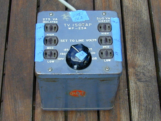
Ready made isolation transformers are readily available, although new ones may
be rather expensive. A cheaper solution is to find a used RCA Isotap, which was
designed for servicing radios and TVs. I got mine for a few dollars at a radio swap meet.

If you're able to add your own plug and socket, Triad makes an inexpensive
transformer
suitable for small radios. You can also build an isolation transformer from scratch,
a topic that has been discussed often in the
Antique Radios forum.
Incidentally, the same risk is present in old "AC/DC" ("series string")
tube radios that did not use a power transformer. Elsewhere in this website
is an article explaining how to modify those radios
for safer operation.
How the Battery Eliminator Works
This circuit is a solid-state version of the classic power supply used in
countless AC-powered tube radios. Here is a brief description of how it works.
Capacitor C3 provides a small amount of AC line filtering. It will prevent
line noise, such as that caused by AC motors in refrigerators, from
entering the B+ supply of the radio and interfering with radio signals.
Capacitor C3 can be omitted if line noise is not a problem in your house.
This was a bigger issue in the days before polarized plugs and grounded
outlets became common. Without this capacitor, if a user encountered line
noise, the common solution was to reverse the plug in the wall outlet.
Resistor R1 offers a small resistance equivalent to the internal resistance
of a selenium rectifier. (Selenium rectifiers are early solid-state
devices, used in many 1940s and 1950s radios). The extra resistance offers
a small margin of surge voltage protection to the capacitors in the R-C
circuit. The surge occurs when the power supply is first powered up. R1 can
be omitted, if desired.
The diode D1 acts as a rectifier, converting your household AC power into DC.
Resistor R2 is an essential part of the R-C network that filters the
incoming pulses of current from the diode. Electrons encounter resistance
as they try to enter R2 and most of them are forced into C1, which fills
with electrons until it reaches its capacity. Then, the remaining electrons
are forced through R2. The inertia of the R-C network absorbs the impact of
the pulsing current and produces a steadier voltage that has the properties
of DC.
Capacitors C1 and C2 eliminate ripple from the rectified DC voltage. C2 is
called the smoothing capacitor.
Resistor R3 is a bleeder resistor that places a load across the power supply, reducing the output voltage to the right amount.
Modifying the Eliminator for 22.5 or 45 Volts
The schematic shown above gives the values for a 90-volt or 67.5-volt
supply. Some radios require 45 or 22.5 volts of B+ current. To lower the
power supply voltage to the desired value, you'll need to make a voltage
divider. Adding a pair of 5-watt wirewound or carbon resistors in series
across the output from B+ to B- easily does this. You'll need to use a
multimeter to determine the correct values for these resistors.
First, build the circuit as shown in the schematic.
Next, follow these steps to determine the values of the two resistors:
- Power up the supply.
- Measure your actual output voltage. For example, you may read 160 volts.
- Divide the required B+ voltage by this voltage. Say, you want exactly
45 volts. 45/160 = .2813.
- Multiply the dividend by 10000. In this example, .2813 * 10000 = 2813.
- Find a 5-watt resistor as close to this value as possible. In this
example, find a 2800-ohm resistor. (Or, find a 2000-ohm resistor and an 800-ohm
resistor and wire them in series; both must be rated at 5 watts.) Call
this resistor R3.
- Subtract R3 from 10000. In this case, 10000 - 2800 = 7200.
- Find a 7200-ohm 5-watt resistor. (Or, find a 7000-ohm resistor and a
200-ohm resistor and wire them in series; both must be rated at 5 watts.).
Call this resistor R4.
- Connect R3 in series with R4.
- Attach the R3 and R4 resistor assembly across the output of the power supply (that is, wire them between the points labeled B+ and B- in the above schematic).
- Attach your DC voltmeter across resistor R3. You should read the desired voltage (in this example, 45 volts).
- If the voltage is correct, attach the leads for your power supply across resistor R3.
That's all there is to it!
Further Suggestions
After the first publication of this article, I got more suggestions
from members of the rec.antiques.radio+phono newsgroup.
Peter Weick offered several interesting ideas:
1. Put two heavier diodes in series. Then, if one fails, the other will act as
a back-up. Feeding AC to any battery radio is not so great an idea.

2. A polarity-indicating LED (the kind that is green in one direction, red in
the other, and yellow when seeing AC) would be very helpful at the output end
of this circuit as well.

3. A neon indicator lamp to let you know when there is current flowing is also
helpful.

4. An On/Off switch fed from a POLARIZED cord/plug helps.

5. A "fast" line-fuse would be helpful. It would not add any personal safety
margin, but it MIGHT protect the downline equipment against diode failure.

6. Running the whole shebang off of a small isolation transformer would be the
best personal safety precaution of all. My little local junk shop has a few
such rated at about 600 ma @ 125V (75 watts) for about $8. They are small
enough and cheap enough that even three of them in a box would not be too-too
much given the added safety.

BTW, my battery eliminator is made up of a box with two of these isolating a
similar series of dropping resistors. I have also added regulation and zeners
for the filament-string supply(s) as I use it on some older battery TRFs as
well. A couple of toggle-switches on top of the box to vary the output
voltages depending on the radio... and there I am.

Of course, this is no longer a $10 item.... more a $25 item. Still cheap at the
price.

Peter Wieck
Building an A/B/C Battery Eliminator
Neil Sutcliffe provided some other interesting information. The first is a two-page
technical sheet for the RCA CV-12 power supply, which dates from around 1940.
The CV-12 unit provided both A (1.5-volt) and B (90-volt) power; if you are an advanced
experimenter, you might enjoy building a modern replica. Here are images of the
CV-12 technical sheets:
RCA CV-12 description
RCA CV-12 schematic
Finally, Neil provided a schematic for his own battery eliminator, which provides
an A supply of 1.5 volts, a B supply that you can set for 22, 44, 66, or 88
volts, and an optional C supply. His design notes appear after the schematic link.
A/B/C Power Supply Schematic
Design notes on Battery Radio Power Supply

In a large majority of battery operated sets, the A, B and C (if used) batteries
must be electrically isolated from each other to allow for the many different
connections of A and B battery polarity required by various radios.

This supply was originally designed for dry battery "farm" radios from the
mid-1930s and later. In those radios, it was most common for the B- voltage to
not return to the chassis, but to be "lifted" by about 560 ohms to develop the
small negative C bias voltage required by the AF output tube. This was done
because the direct heated cathode could not be lifted from ground as done in
AC operated sets.

Therefore, when building or adapting this design, be sure that each output
circuit is mutually isolated from each of the others. Remember, too, that
the heat sink tab on the LM317 is connected internally to the circuit and
must be insulated from any circuit connection.

While the Hammond 229A12 is a good choice for the power transformer, it can be
a bit pricey. There are options if one wants to use the contents of the "junque
boxe" or wants a bit more output power for tubes like the '01A or '99. For more
filament power, one can choose a filament transformer (low voltage rectifier
transformer) with a "resistive" rating of at least twice the DC current needed
and about 4V (or more) higher voltage rating than the desired filament voltage.

Even though the specified transformer is rated at 6.3VAC per secondary and the
ideal rectified voltage appearing on C1 should be 6.3 x 1.414 = 8.9V, one must
allow for the forward drop in the bridge rectifier diodes as well as the IR
drop in the transformer and still have ample overhead voltage for the LM317
even at the trough of the ripple. Also consider that the excess voltage between
the raw DC on C1 and the output voltage must be dissipated in the LM317
regulator. Thus, as the load current requirement increases, so does the need
for proper heat sinking of the regulator.

Another source for inexpensive isolation transformers for the B+ section is
the transformer used in old bathroom razor outlets. These are commonly found
at garage sales for a couple of dollars.

I have added an optional isolated "Bias" supply to the schematic at the request
of a restorer wanting to power a Radiola III. Such a supply is also needed in
a good number of other early battery radio sets, well into the 1930s. Its
circuit is identical to the filament supply except that the voltage setting
resistor is selected for the desired voltage up to about 5V.

Vout	Rselect
  2	  160
  3	  360
  4	  560
  5	  760

These values also apply to the filament supply if one wants to increase the
output for 2V tubes such as the '30 and 1H4G, but much over 2V will require an
increase of the transformer secondary voltage as mentioned above. If you
increase the filament voltage from 1.5V, omit the three "safety diodes" across
the  filament output.

Neil Sutcliffe, (C) Copyright 2010
Thanks to Peter and Neil for offering these additional ideas and information
sources.
This radio construction project, including all descriptions, diagrams, photos, and the underlying electronic design, is published here for the noncommercial use of radio hobbyists. You may print and reproduce these project instructions for your personal use. Commercial use of this material is strictly forbidden.
|
