Triumph Model 830 Oscillograph-Wobbulator (1943)


Say, Wobbu-what? Yes, folks, that's the real name. This instrument looks a lot like
an old oscilloscope—which it is, in fact—but it also combines a type of sweep
generator known as a wobbulator.
I saw this item at a local shop, very dirty and forlorn. I was intrigued by the
odd name and the reasonable pricetag, but passed it by. A couple of days later,
Curt Schreiber posted a restoration question about the very same device in the
rec.antiques.radio+phono newsgroup.
Here is Curt's description of this device:
A wobbulator is basically a sweep generator so that
I.F. transformers can be "flat-topped" rather than peaked.
This alignment technique was called for with the "high
fidelity" sets that sported broad-band I.F. strips. (Whether
this provided for a better listening experience might be a
topic for debate.) A plain wobbulator is a device that
would be hooked up to a scope in conjunction with an R.F.
(really an I.F.) signal generator. The Oscillograph-Wobbulator
is a scope with a built in wobbulator.
Armed with a little more knowledge, I revisited the shop and decided
to take a chance on it. The 'scope was loose in its case and terribly dirty,
but all of the knobs were present and it showed no obvious signs of abuse.
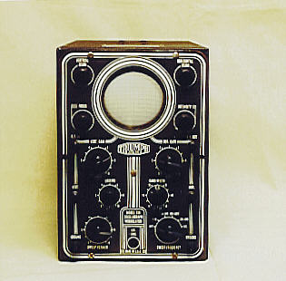
The next photo shows the front of the oscillograph-wobbulator after I cleaned it up.
Again cribbing from Curt Schreiber's message, here is his description of
the tube lineup and controls.
Picture tube is a 3AP1 (I presume electrostatic deflection?)
Other tubes: 1V, 6K8, 884, 6SJ7 (2 of them), 6J5, and 6X5.
The power transformer has 115VAC primary, and an 800V CT
secondary (also filament voltages).

There are 4 controls around the screen: Vertical Beam, Horizontal
Beam, Intensity, and Focus. On the left side of the lower panel
are three contacts (R.F. In, Vert., and Ground) and three controls
(Vert. Gain, Locking, and Sweep Vernier).

On the right side of the lower panel are three contacts (R.F. Out,
Hor., and Ground) and three controls (Hor. Gain, Band Width,
and Sweep Frequency). At the very bottom there is a jack for
Ext. Sync.

The Vertical Gain control is calibrated with "Direct" and then
"0-10". The Horizontal Gain control has the same calibrations.
The Locking control has a switch that locks in at 60 cycles. After
the switch is turned it is then a variable control calibrated "0-10".

The Band Width control has a switch with "R.F. Off" and then K.C.
calibrated "0-50". The Sweep Vernier control is calibrated "0-10".
The Sweep Frequency control is a 6 position switch "Off, 7-70,
60-600, 500-5000, 3M-30M, and R.F."
Restoration Notes
I have gotten pretty confident about my ability to restore old radios,
but restoring old test equipment is a different proposition. The ills
that afflict old radios—leaky capacitors, bad tubes, and so on—are
often shared by test instruments. However, fixing a test device may
introduce a chicken-and-egg problem. How do you calibrate the calibrator?
An incorrectly-calibrated measurement instrument is useless.
I don't have any special expertise in fixing test gear, but this device
piqued my curiosity, and I had very little invested in it. I decided to
crack it open and see what happened.
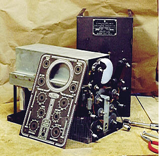
The first step, as always, was to clean up the device and shoot some
contact cleaner into its controls. The next photo shows the oscillograph-wobbulator
on my workbench, partially disassembled.
Internally, the device showed good build quality. Everything was nicely
laid out and the construction was robust. That's consistent with
this unit's military role. Riveted to the top of the case is a metal
plate stating that it was manufactured for the Navy under a contract
dated November, 1943.
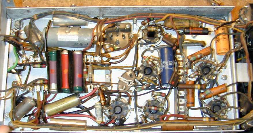
This instrument had been serviced somewhere along the line. A few of the capacitors
looked like replacements. Here's a view of part of the chassis.
After spiffing things up, I put the device back into its case and cautiously
powered it up on my variac. I also connected the audio output from a
small radio to its vertical and horizontal inputs, to see whether it would
display anything.
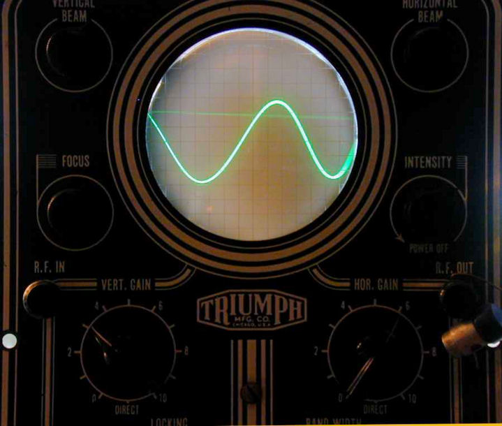
To my delight, it started up without any problems and seemed to work,
with a bright green trace. Here's the scope displaying a simple sine wave.
That's as far as I had gotten by June, 1999. As in every restoration,
even if the device nominally works, I would normally go on to replace all of the
paper capacitors and the filter capacitors in the power supply.
A few years later, the Triumph still sat on a shelf and I was contacted by a group who were restoring
a World War II Navy vessel to become a museum. They were interested in the Triumph to help
outfit the electronics shack. I sold it to them, and now my little 830 is not
only operational but back in the Navy where it started out.
In 2011, about a dozen years after I first wrote this article, I was contacted by
Richard Sears regarding his Triumph 830 restoration. His
post
includes a full schematic and provides details about how the 830 works.
|