Zenith Model 8G005Y TransOceanic Radio (1947)


This set was made around 1947, closely following the end of World War II.
By the time the wartime manufacturing hiatus ended, Zenith had redesigned the
original Clipper, producing this handsome and dramatic
multi-band portable.
In this article, I describe the Model 8G005 and
describe restoration techniques that apply to this
and other tube TransOceanics.
Description
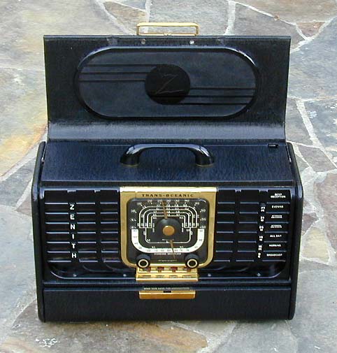
The sweeping lines and bold colors of this radio give an impression of
power without too much complexity. It's an outstanding example
of postwar industrial design.
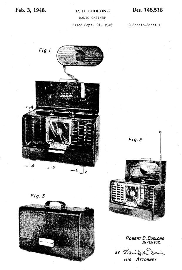
Here is the U.S. patent drawing for this TransOceanic. It
was created by Robert Budlong, who designed many memorable
Zenith cabinets.
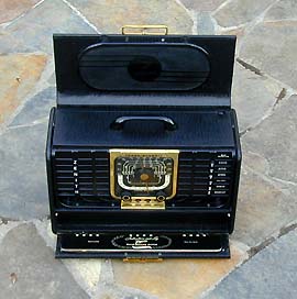
The postwar TransOceanic case is only slightly wider and taller than the original
Clipper case, but it appears much bigger when open because the case front flips
up instead of down. The flip-up cover was a definite
improvement over the removable Clipper cover, which often was lost.
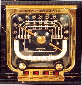
The gorgeous tuning dial occupies front and center, with a lacquered brass bezel surrounding the dial and incorporating the four red Radiorgan tone switches below.
(Sticklers may notice that this picture was taken from my second 8G005, which had incorrect
knobs at the time. Never mind—I replaced them after I took that photo.)
The six bandswitches stand in a column to the right of the dial, an
arrangement that didn't change until the very last transistor TransOceanics.
The bottom of the case front also flips down to
expose the integrated
operator's manual—about a dozen slender pages printed on stiff black
paper and permanently mounted with a wire-O type binding.
The integrated operator's manual is unique to the 7G605 and 8G005 models. It's a
great user-friendly feature. Later models of tube TransOceanic eliminated
the flip-down cover to reduce manufacturing costs. On those radios,
the manual is a separate booklet that can be clipped inside the back cover.
In defense of the detached manuals, they also include much more information,
including a complete schematic, so consumers gained extra content at the price
of reduced convenience.
The case is covered in "Black Stag" leatherette, the most
common covering for tube-powered TransOceanics. The rare military R-520/URR
came in brown oilcloth and brown leather became an extra-cost option during
the later 600 series.
When closed, the
radio looks like a chunky black overnight case. Only the Zenith logo on the large
brass clasp tells you there's a radio inside. TransOceanic experts can always spot
an 8G005 with the cabinet closed, however, because the sides are slightly beveled—a
subtle design feature that disappeared in later models.
Note that the carrying handle is rigid and rather thin. These handles are easily broken, so
I always carry my 8G005 from the bottom.
In this model, the AM portion of the Wavemagnet antenna has migrated up to the
flip-up lid. It's the black oval plastic plate with the lightning Z
logo.
Two other antennas are provided for shortwave reception.
The telescopic Waverod antenna pops straight up when you press a catch,
unlike the original Waverod, which had to be rotated into position after
opening the back.
The popup Waverod was a TransOceanic trademark throughout the 1950s and 1960s. In
later transistor models, the extensible antenna was concealed within
a hinged carrying handle, which proved to be quite fragile.
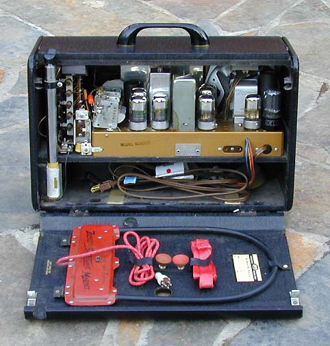
The third antenna is the bright red Zenith Shortwave Magnet, stowed with
two clips inside the back cover. This antenna was provided for use while
traveling in a train or airplane. You plugged its cable into the radio
and stuck the antenna onto a window by its rubber suction cups.
The compartment below the chassis is where you would place the large
TransOceanic battery.
The TransOceanic is easy to use compared to most shortwave receivers of the time.
The bandswitch buttons are labeled with information
about the best time of day for reception in each band, and the tone switches
and other controls leave nothing to doubt.
Although lacking boatanchor features
such as a separate bandspread tuner or variable selectivity, the
TransOceanic still delivers outstanding shortwave performance. It uses
electronic bandspread in the shortwave bands, which, in plain English,
means that the stations are more spread out than they would be otherwise.
On a shortwave set lacking bandspread, it may require the fingers of
a brain surgeon to tune in your favorite stations!
This radio does not have a dial lamp, an intentional feature aimed at prolonging
battery life. A red flag does appear in the dial when it's switched on, however.
Tube TransOceanics also have a volume control that doesn't go to
complete silence when you turn it all the way down.
The radio is faintly audible at minimum volume, reminding
you that it's still turned on and consuming battery power.
The headphone jacks are on the rear of the chassis. Later models moved the headphone
jack to the front panel and added a dial lamp with a slide-and-hold switch on
the front.
I purchased this set in excellent original condition.
It reigned as a gorgeous but never used "shelf queen" for several years, until I decided to restore it as my Dad's 75th birthday present. The rest of this article describes
that restoration. Although the remarks are specific to this model,
many of the procedures will apply to all tube TransOceanics.
Restoration
The rest of this article describes how I restored this radio for my Dad. Many of these procedures apply to other models of
tube TransOceanic.
Chassis Removal
Let's begin by removing the chassis.
First, slide off the two black knobs from the front of the dial.
Use a small container to store these and other small parts during restoration.
Release the back cover by sticking a finger inside the round hole and pulling. The Waverod
antenna must come out before the chassis.
Carefully pull out its thin black antenna wire where it plugs into the nearby
phenolic strip. Grasp the metal end of the wire rather than pulling on the wire
itself. Now remove the two nuts that secure the antenna base mount to the left
bottom side of the cabinet. A socket wrench with a deep socket works best.
Put a rubber band around the sections of the antenna base mount to keep them together, and
set the antenna aside. Put the mounting nuts back on their screws so they won't be lost.
Near top left of the cabinet is a black wooden block that braces the bandswitch tower
from behind. Remove its screw and put the block and screw in your small parts container.
Gently pull out the two other antenna wires that connect the AM Wavemagnet
antenna to the phenolic strip and the main tuner frame.
Now you are ready to remove
the chassis mounting screws and slide the chassis out of the cabinet.
You can reach the two chassis mounting screws from underneath the wooden platform.
There's not much space inside the battery compartment, so you'll need
either a very short screwdriver or one with a 90-degree angled tip.
After removing the chassis screws, carefully slide the chassis out of the cabinet, taking
care not to snag the two antenna wires hanging from above. Avoid grabbing
the fragile coils at the left of the chassis.
The following photos show the chassis out of the cabinet.
Set the chassis aside in a safe place until you're ready to tackle the electronics.
After you have removed the chassis, the black bandswitch buttons will fall loose
into the cabinet. They are backed with a black felt strip. Put
those in your small parts container.
Cleaning the Cabinet and Faceplate
Begin by giving the cabinet exterior a thorough cleaning.
The black leatherette covering is durable, but you don't want to scrub it
too hard or use an abrasive or caustic cleaner. I cleaned the leatherette with mild soapy
water, plenty of paper towels, and a soft children's toothbrush for stubborn spots.
Now you can clean the black plastic front panel, brass dial bezel,
and clear dial cover.
Soapy water or a mild glass cleaner such as Windex works well.
Use a toothbrush and Q-tips for the many corners. Don't soak the
cloth behind the speaker grille unnecessarily. A hand vacuum works well for
getting dust out of the cabinet interior.
Polishing Plastic and Metal Parts
After you have removed surface dirt and gunk from the plastic and metal parts,
you can polish them with Novus Plastic Polish #2, available from
Antique Electronic Supply.
Use a soft, lint-free cloth and Q-tips.
The clear plastic dial cover is fragile. Support it with one hand and a clean cloth from
behind while polishing the front. Then turn the cabinet and polish the inside of
the cover. It is normal for the plastic to be slightly yellowed or darkened with age,
so don't worry if your dial cover looks shiny but is not crystal clear.
Now shine up your black knobs and the six bandswitch buttons.
The grooves in the knobs are typically filled with old dirt. Soak them in warm soapy water
for a while, and then use a fingernail brush, toothbrush, or toothpick to get out all the dirt.
Also polish the carrying handle and plastic AM Wavemagnet inside the front cover.
Some times, a bit of the white lettering may be worn from the bandswitch buttons or
the ZENITH name on the front panel.
This is easy to restore. With a fine brush,
flow a little white paint into the recessed letters. Use the edge of a business card
to gently scrape across the surface of the button, removing excess paint from the surface.
There may be a slight haze of white paint left behind, which is easily dealt with.
Let the white paint set up for a minute or two, then apply a small amount
of lacquer thinner to another
business card and gently wipe its flat surface across the flat surface of the button.
You can read more about restoring engraved lettering in my article about the
Hallicrafters SX-28.
The metal parts—dial bezel and cabinet latch—are brass covered with protective
lacquer. It's common for some of the lacquer to be worn
away. Don't polish these parts too hard, or you may remove what lacquer is left.
If your polishing cloth comes away black, then you are
polishing the underlying brass. This is not a big problem. Novus #2 will make the
brass shiny and keep it that way for quite a while.
I prefer not to strip and relacquer the brass parts unless the finish
is severely damaged. Your set will look more authentic if you
retain the aged brass look as much as possible. The latch is secured by
two mounting screws on the opposite side of the front panel. The dial bezel is
much more difficult to remove and I would leave that job to an expert.
If you do
strip and relacquer the brass parts, you can get an aged look by mixing a small amount
of orange tint with the lacquer.
Restoring the Leatherette Cabinet
Most tube TransOceanics have a "Black Stag" leatherette cover. The only exceptions are the brown leather-covered models such as my A600L and the extremely rare military R-520/URR.
Leatherette is
simply fabric with vinyl coating patterned to look like leather. After you clean it up, the black leatherette may look dull. Don't worry about that for now. You'll want to deal with wear damage first.
On a set with average wear, the corners may have a few strings hanging loose.
These are broken threads from the fabric that underlies the vinyl coating. Put a small dab of
household glue on the tip of your finger and smooth the threads back into place.
Some times the covering will come loose at a corner. This is simple to fix.
Hold back the loose part and paint
some glue inside with a flat blade. Then gently clamp the area until the glue dries.
If you put pieces of wax paper between your clamp and the covering, you'll avoid
gluing a new "accessory" to your TransOceanic.
On a seriously worn cabinet, the covering may be completely abraded from the corners,
exposing the plywood cabinet body underneath. If there is enough frayed material to work
with, you can smooth it back over the corner with glue,
just as a bald man does a "comb-over" with his few remaining hairs. Dampening the loose
material beforehand will soften it up and make it more flexible. After
you dye the cabinet black (explained below), the repair may not be too noticeable.
A vinyl repair kit can be used to patch gouges in the flat areas, as well as
more seriously damaged corners. Look for a kit with a graining or texturing patch,
which allows you to mold a textured pattern into the surface of the repair material.
If the repaired area is not large, a slight difference in texture will not matter.
Following cleaning and any repairs, you can dye the leatherette.
Use ordinary Kiwi black liquid shoe dye (not polish), available at
grocery and drug stores. Apply the dye smoothly, without slopping too much on
the plastic parts.
Your goal is to make the covering an even black color. If you
get some dye on the plastic or brass parts, wipe it off while wet with a paper towel,
or, if it has dried, polish it off with a dab of Novus Polish #2. If the
color looks uneven after applying a coat of dye, you can apply a second coat.
After dyeing the cover, some people like to apply some other substance
to obtain a slightly shinier look. I don't normally do this, because the dye makes
the cover shiny enough for my taste, and substances such as wax shoe polish or
Armor-All are temporary coatings that must be reapplied (or removed and reapplied)
periodically. Keep in mind that, when your TransOceanic came out of the factory, its new
leatherette had a certain luster, but not a mirror-bright gloss!
Cabinets with catastrophic cover damage will need to be completely recovered. Factory replacement
leatherette is no longer available, but you can get closely matching leatherette
from Scott McAuley at Cayce Vintage Sound Company, cavisco@aol.com . Scott's advice on recovering appears here:
----- Original Message -----
From: CAVISCO@aol.com

My best advice on how to recover a set is to take detailed
notes and save the old material as a pattern. Damp cloths
laid over the old cover material overnight will usually
loosen the old hide glue, allowing the removal of the old
material intact.

I have had good results dealing with the rear door brass
ring by covering over the back completely, allowing that to
dry completely, apply fresh adhesive to the backside through
the pull hole, then use a large mechanics socket and a
woodworking clamp to stretch/clamp the material around the
brass ring. Once this has dried overnight, you can remove
the clamp and use a sharp pen knife to trim around the ring.

I have never had any luck removing the door hinges without
damage. I now just pop the hinge pin out with a small drift
punch.

The cabinet feet vary slightly from year to year and can also
prove difficult to remove. On some models I have been able
to straighten the post from the inside of the cabinet and
remove the feet. The plastic feet used on the later models
are the worst. I think they are impossible to remove without
wrecking the feet, the cabinet, or both. Unless I am certain
I can remove them safely, I will just work around them
working the edge of the material under the feet with a thin
putty knife.
Model 8G005 Electronics
With eight tubes, Model 8G005 has the most complex electronics
of any tube TransOceanic. Three of those tubes (two amplifiers and one inverter)
are devoted to a push-pull type audio section, which, together with the
generous speaker mounted in a wooden cabinet, offers superior sound quality.
Later models of tube TransOceanics updated this design with
all-glass tubes and expanded band coverage, but their basic
performance was not dramatically better than this pioneering model.
Before starting any electronic restoration, you should
get a schematic to guide your work and help you understand the electronics.
You can download the 8G005 schematic from the
Nostalgia Air site.
If you prefer a more readable paper copy, contact one of the sources
from our Parts page.
Zenith produced three variants of the 8G005Y radio. Mine is the original
model, with chassis 8C40. It was produced in 1946 and 1947. Later variants
8G005YTZ1 (1948) and 8G005YTZ2 (1949) used all-glass mini rectifier tubes,
and have chassis numbers 8C40TZ1 and 8C40TZ2, respectively. Be sure to specify
the correct model when ordering a schematic, since some components in the
power supply will be different.
All tubes in the 8G005 are the loctal type, as in the original Clipper.
The tube lineup appears below.
| Tube |
Type |
Function |
| V1 |
1LN5 |
RF amplifier |
| V2 |
1LA6 |
Converter |
| V3 |
1LN5 |
IF amplifier |
| V4 |
1LD5 |
Detector/AVC/AF amp |
| V5 |
1LE3 |
Phase inverter |
| V6 |
1LB4 |
Audio output |
| V7 |
1LB4 |
Audio output |
| V8 |
117Z6 |
Rectifier |
Apart for the 117Z6 AC rectifier, all of these are 1-volt tubes.
The low current requirement makes them ideal for a battery-powered radio.
Cleaning and Lubrication
Portable radios are typically clean inside, but if there is
any dust on the chassis, clean it up now, using Windex sprayed onto a paper towel.
Next, clean the controls with a spray cleaner such as DeOxit.
These include the power/volume switch, tone controls, and bandswitches.
Spray a small amount of cleaner inside each control, reaching its contacts,
and then work it normally through its full travel for a minute or so, to
remove old gunk and corrosion.
DeOxit is also used to clean the tube sockets and pins. Remove each tube, spray
a little cleaner into the socket, then insert and remove the tube several times.
If any tube pins appear badly corroded, you can shine them up with very
fine (400 or higher) sandpaper.
If the dial appears hazy, clean it carefully with Windex on a paper towel.
Be careful not to snag the fragile dial pointer.
The bearings of the tuning capacitor can be lubricated with a drop or two of light oil.
Don't overdo it.
If the capacitor is very stiff, the old lubricant may be
dried out. You can use a small amount of WD-40 to loosen it, followed by
normal lubrication. (WD-40 is a solvent, not a lubricant, so you
should always apply lubricant after using it.)
Don't get any oil on the tuner string. That will cause it to slip.
I placed the chassis upside down on the bench to do the under-chassis work.
To keep the chassis stable in this position, I folded a piece of
thick cardboard and taped it to the top of the centermost IF transformer can,
making the chassis more level.
Note that this AC/DC type of radio can have a "hot" chassis, meaning that you
can get a nasty, even fatal, shock by touching
the chassis while powered up. For safety, avoid
touching the bare chassis whenever the radio is plugged in. It's also a good
idea to power the radio through an isolation transformer during restoration.
If you plan to test the radio while on the workbench, replace the knobs
on the tuner and power/volume controls.
Replacing the Power Resistor
The instant that I looked under the chassis, I could see that a fat
power resistor had burned to the point where nothing was left of its
center but a coil of bare wire. The next
photo shows the chassis before restoration, with a yellow arrow pointing
to the bad resistor.
The next photo shows a close-up of the "skeletonized" resistor.
Needless to say, we don't want to leave this sort of relic in place!
The schematic calls for an 88-ohm, 2-watt resistor. Not having one of those
on hand, I fashioned a substitute by wiring together two 1-watt resistors
in parallel, with resistance that equaled 88 ohms. Just for kicks, I tested
the resistance of the destroyed resistor after removing it. Despite its appearance,
it tested at 89 ohms! Bad capacitors in the circuit had burned away almost all
of its insulation, but its resistance was still well within the manufacturer's
original specifications.
Adding Power Protection
As a safety precaution, it's a good idea to add a 1-amp
fuse to the AC power line. Install the fuse on the leg of the power line that
goes to the power switch. Another option is to run your TransOceanic
from a power strip that has a 1-amp circuit breaker.
You can also install a varistor on each leg of
the power line, if you like. A varistor softens the initial rush of current to the tubes
by starting out with a high (say, 120 ohms) resistance and then going down to
a negligible (say, 2 ohms) resistance. Some folks believe that a softer startup
extends the life of low-voltage tubes, an especially important factor for the
expensive 1L6 tube used in later TransOceanics.
Replacing Capacitors
The next phase involved replacing the old paper and electrolytic capacitors. This
procedure is described in detail in our article, Replacing
Capacitors in Old Radios. The next photo shows
the chassis near the end of capacitor replacement.
Recapping this "original recipe" 8G005Y was not too difficult, but later models of
tube TransOceanic have a more cramped layout, requiring that you temporarily
remove other components to reach the old paper capacitors.
If you are restoring
one of the later models, I encourage you to take the extra time to reach all
of the old paper caps. Invariably, the one that you don't replace is the one that
fails next! As long as you have the chassis on your workbench, go ahead and do a
thorough job. It doesn't require rocket science to temporarily remove other
components, as long as you take notes and make sketches as needed to guide
you back to Kansas. Having the schematic in hand is essential, as well.
After the capacitors had been replaced, I touched up the alignment, gave the set
a thorough bench test, and reassembled it.
When you reassemble the radio, be sure to get the bandswitch buttons in the
right spots. The BC button goes at the bottom and the others go in ascending
numerical order from bottom to top (16M, 19M, etc.).
Final Thoughts
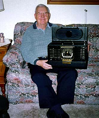
This radio was restored for my Dad as his 75th birthday present. Here's a photo of him
with his "new old" TransOceanic 8G005Y radio.
This project was memorable in a couple of ways. It was my first complete restoration
of a Zenith TransOceanic and it also provided a nice gift.
When this radio was built,
WWII had just ended, my Dad had been released from military service, and he was soon
to start a family. The radio is a few years older than I am, but it represents
an important time in radio history as well as our family history.
I own one other 8G series TransOceanic, a Model 8G005YTZ1. It's identical to this one except for a change in the rectifier tube.
Happy collecting!
|