|

Building a Tube-Powered Theremin
by Craig Hanson


I decided to build a Theremin for my two science-minded
teenage daughters. After researching, I concluded that I wanted to build with
tubes, yet I wanted to avoid having to hand-wind custom coils. Elsewhere in
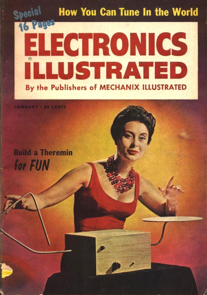
this website, I found a
building article from the
January, 1961 issue of Electronics Illustrated magazine.

This particular
design seemed to present the best overall package, yet I could find nary a
build report anywhere.
I suspected a fundamental flaw was lurking in the
design that led to universal failure, but decided to give it a try anyway. In
the end, the construction presented no serious problems and I am thrilled
with the performance. I have no idea why dozens of these haven't been built and
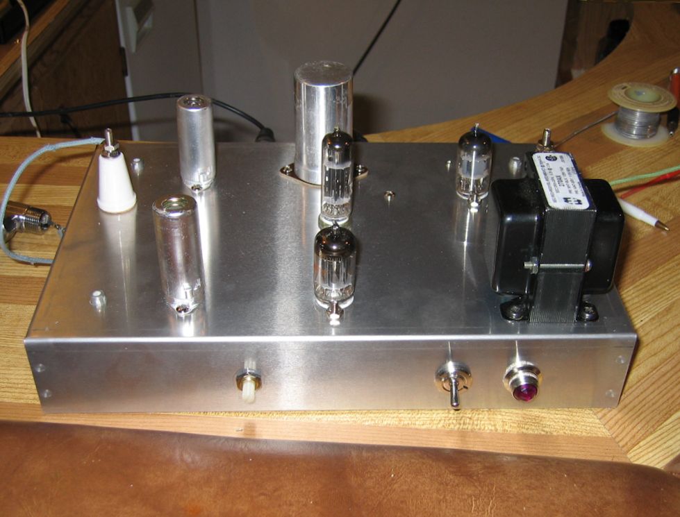
reported on, because it is a very nice performing project. Here are a few photos
of my completed Theremin:
As for my experience level, I am still on the steep part of
the tube learning curve. I have restored a half dozen tube radios (AA5's and farm
battery sets), and built dozens of simple solid state guitar effects and basic
stamp projects. But with that background and for a first-time tube build, this
project was perfect.
Parts sourcing was not difficult. I
have been collecting tubes now for a few years so I had all the tubes on hand
in NOS. Most of the other parts were ordered from Antique Electronic Supply
and Radio Daze. Some specialized parts were hunted down and
captured from other sources which I will provide.
If you read and work through the article to understand what
is happening, anyone with a moderate level of experience should be
able to pull this off. My observations and build variations were as follows:
My greatest concern as I started into this was that the thing looked like a
textbook-perfect breeding ground for hum. There are local grounds taken to
chassis all over the place, AC
laying almost on top of signal carrying conductors, and
no shielded signal lines.
Perhaps the fact that there is no serious
amplification occurring within the circuit minimizes
the risk of hum, but the original author noted that layout was important
and cautioned to cross AC and signal wires at right angles to each other.
Maybe that alone would have been sufficient, but I took additional
precautions.
Instead of connecting one side of the filaments and filament
winding of the PT to ground as shown in the schematic, I ran two closely
twisted solid filament wires to each tube and implemented an
artifical center tap on the filament circuit using two
matched 100 ohm resistors from each filament leg to ground. Then I subbed
two .05 mf SBE type PS orange drop caps across the resistors in place of
C24 as shown in the schematic.
Finally, I implemented a star grounding
scheme, taking all the grounds from each "stage" to a common but
chassis-isolated "local" grounding tab, and then tying all the local
grounds to a single chassis-connected ground. I saved the use of shielded
wire as a last resort, but found it unnecessary, as with the measures
described, there was no detectable hum even at high volume levels.
The original chassis specified in the article measured 11" by 7" by 2". The
closest Hammond chassis made is actually 12" by 8" by 2", which I used and
which seemed to work fine. I stuck to the original chassis layout as shown
in the article and simply scaled things out proportionally. A few
component leads that were probably adequate for a point to point build on
the original chassis ended up coming out a little short as a result, but
the standard "soldered-splice lead-extension" approach worked just fine.
Bare leads that were at risk of shorting to other nearby leads were
dressing with heat shrink tubing before soldering.
I used an IEC socket for the AC
connection, which of course gave me a true U-ground connection which went
to the chassis star ground. The line connection of the PT primary was
fused and switched and the neutral connection was bypassed to chassis
ground through C25, as shown in the original article.
I used a 1/4" Switchcraft jack for the output connection
and isolated it from the chassis with shoulder washers, versus the chassis-grounded phono
connector of the original build.
I selected the Hammond 270AX as my PT, as its
specs matched closest to those of the original article. The chassis and PT
were slightly cheaper from Radio Daze than AES. My power supply
multi-section cap was 40-20-20 @ 500V by CP Manufacturing, available from AES.
The antennae of the original build were shown to be quite large, but I found
the Moog antennae set worked just fine. Moog manufactures solid state
theremins in completed and kit form, and were quite
happy to sell their antennae set for $40 plus shipping. It's worth it.
Antennae mounting is accomplished with standard plumbing type chromed
compression-to-pipe-thread adapters. You have to drill and tap a small
hole on the inside of the pipe threaded part to attach a solder lug. Do a web search for
Moog Etherwave assembly instructions and it is explained well.
I acquired a 500 Khz
crystal in the large can (HC33U) format
and I was able to mount it under the chassis and connect it directly
without the socket as specified in the article. The article
notes that others on multiples of 500 kHz will also work, so there are
lots of options here.
Porcelain feed-through insulators are an uncommon part, but I
got mine from
Electronics and Cable in Dover, NJ.
I have seen similar ones in batches of assorted electronic parts on eBay.
I installed the pilot light in the front panel and connected it
directly to the nearby filament circuit filter/artificial ground network as opposed
to connecting it remotely with a twisted wire pair.
All resistors are the 1W carbon film type from AES, except where larger
ratings were specified.
All mF
size caps are the "Illinois" metalized polypropylene tubular from AES,
except the power supply e-caps and the filament circuit center-tap caps as
previously noted. The pF size caps are the
polystyrene film tubulars from Radio Daze.
Filament
wire was old Radio Shack 20-gauge solid vinyl insulated, which was not the
best choice as the grade of vinyl was quite soft and tended to melt easily
with any excess soldering heat. I had to rip out and replace lengths of
twisted pair on a number of occasions because of this, but I don't expect
any further problems with it from this point on.
All other wire was the
cloth covered 20-gauge stranded from AES, which only has a 300 volt
rating, but it should be adequate for this purpose. Note that if you
progress to building tube amplifiers, check your plate voltage specs:
many designs run HT voltages considerably higher than 300v, and you will
want to select your wire accordingly.
There
were a couple of errors in the original article that you may or may not
detect, so I am listing here the ones that I found.
First is the labeling
of the three coils on the photo of the chassis top in the article. One is
labeled L1 while the other two are both labeled L3. The one on the
right hand side of the photo is actually L2.
Second is the
symbology used for the two 1N34A germanium diodes.
This may not be an error so much as an anachronism. (The article was
written the year I was born, after all). The diode symbols are shown with
their cathodes marked as +. My training was that the cathode is the
negative terminal of a diode, and the anode is the positive terminal, so
this was confusing for me, and I ended up installing the diodes backwards.
As you might guess, that didn't work very well. The correct orientation
for the diodes is as shown by the symbol on the schematic. The + sign
should be ignored, and the green band on the physical diode indicates the
cathode end. (I have seen this same curious indication with the + sign
on the cathode on other schematics from around the same era, but I've no
idea what it is supposed to mean.)
Third is the instruction for adjusting
the slugs in the coils where L1 is to be set so that "about 1/2 inch of the screw protrudes
above the chassis." There are no protruding screws in these coils.
Instead, the slugs are threaded directly into the coil forms and are
adjusted by inserting a plastic hex tuning tool into a hole in the
center of the slugs and turning them. When tuning, I
simply turned the slug of L1 about three turns counter-clockwise, which
moved it up from the bottom of the coil form into the coil by about 3/8
inch, and this worked fine. The rest of the tuning went as described in
the article, and my final positions for L2 and L3 were close to the top of
the coil forms.
The extra switch on my unit beside the output jack is provided to disconnect
the diode that is shown connected across the output jack in the original
article. The effect of this diode is noticeable but not dramatic, but
Theremin "sound" is subject to individual taste, so I
reasoned that offering a choice here might be desirable.
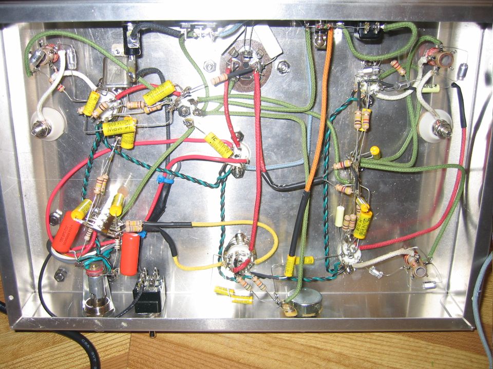
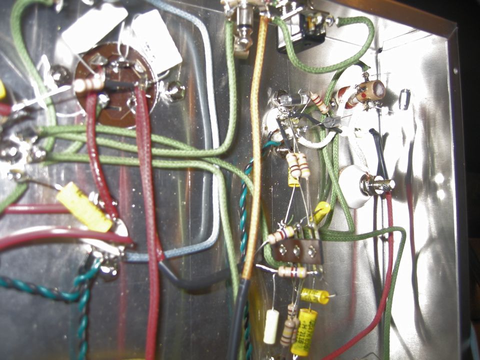
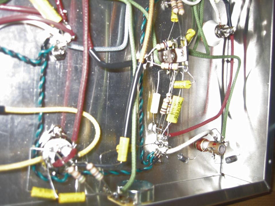
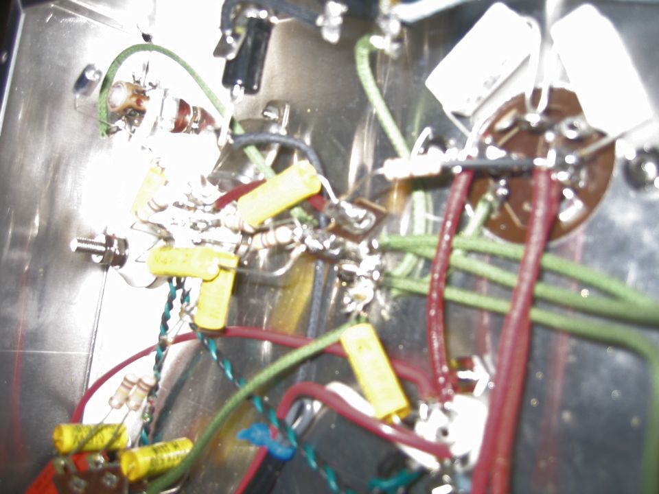
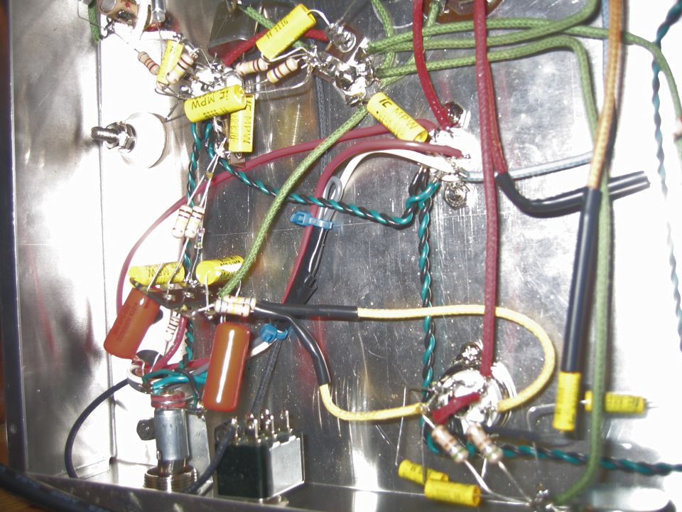
Below are several photos of the chassis internals:


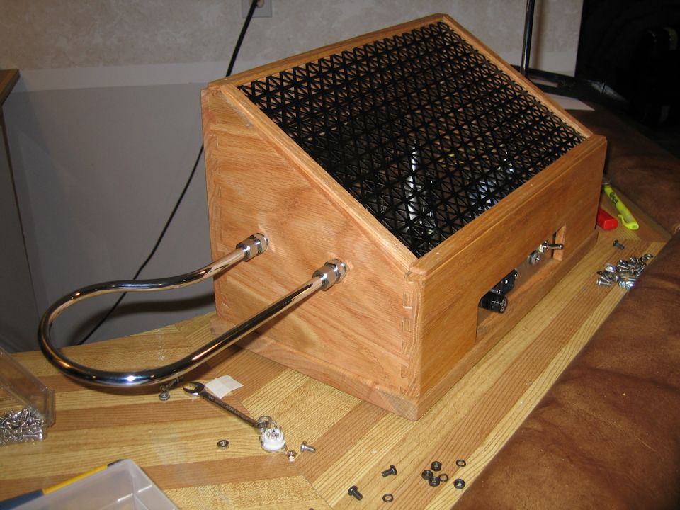
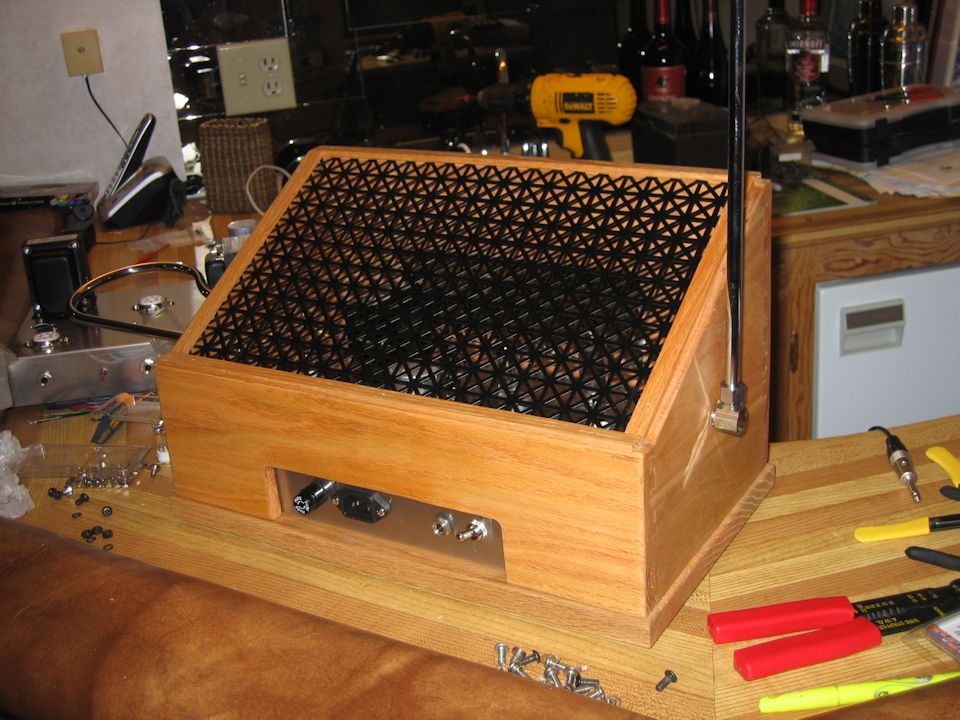
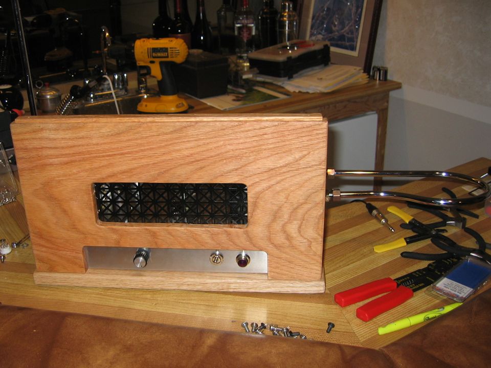
After checking it out on the bench, I built the unit into a wooden
cabinet, shown in these photos:


Final Thoughts
Note that the audio output of this unit is "instrument level," meaning that
it will require additional amplification and a speaker to be audible. You could
(carefully!) connect it to an unused input in your home stereo system, but that
generally doesn't work well. If you've ever tried it with other electronic instruments
like guitars or keyboards, you'll know what I mean. Fried inputs and blown speakers
don't necessarily result, but they could if you accidentally do something wrong.
Better is to use (or build) a dedicated instrument amp, such as this 1955
Dynaco design.
I built it with 6AQ5 tubes and incorporated an eye-tube as a signal indicator, but that's another story!
Anyway, if this Theremin project looks appealing, I'd strongly recommend that
you give it a try. As a legacy-type project, it was just as easy to build today
as it probably ever was, and the end result blows the doors off its more modern,
solid-state counterparts. Have fun!
Craig Hanson
This radio construction project, including all descriptions, diagrams, photos, and the underlying electronic design, is published here for the noncommercial use of radio hobbyists. You may print and reproduce these project instructions for your personal use. Commercial use of this material is strictly forbidden. Kindly do not attempt this project if you are unable to work around high voltage safely.
|