Farnsworth Model GT-051 Bakelite Radio (1948)


 Schematic
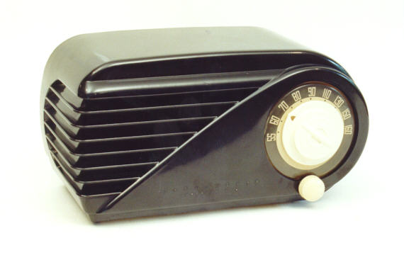
"Black Beauty" is my nickname for this classy Bakelite set.
Sporting a dramatic, assymetrical design, with deep
wraparound louvers and a bullet-like profile, it's
a great example of 1940s Streamline design. Definitely
a keeper, in other words! I'm restoring
the electronics of this radio as well as the cabinet,
so let's look at some highlights of each process.
Cabinet Restoration
This radio came from the factory with an ivory paint
job. By the time I got my hands on it, though, the paint was deeply
chipped in many places. After spending some time trying to
smooth out the chipped spots, many of which were on
the delicate edges of the louvers, I gave up and removed
the paint with a chemical stripper. I don't normally
resort to such drastic measures, but the original paint simply
wasn't salvageable.
Before removing the old paint, I brought the cabinet to an auto
parts store and found a can of spray paint that looks like a
great color match. When it's time to repaint, I'll have exactly
what I need. I also carefully masked the bottom
to preserve the original paper labels. I first taped a layer of
plastic over the labels, using blue "painter's" masking tape,
then covered that layer entirely with a second layer of tape.
Stripping the cabinet took a couple of hours. I worked outdoors
on our deck, using a brush-on liquid stripper. From aluminum foil,
I formed a temporary container about the size of a cakepan
to catch the excess stripper and old paint. Most of the
paint brushed off after softening, but a few
areas required some careful scraping. For the flattish areas,
I used an old putty knife that once belonged to my grandfather.
For close crannies and details such as the raised Farnsworth
lettering, I used various smaller tools, including toothpicks
and a straight pin. Click the thumbnail images to get a closer
view of the process.
As the paint came off, I was a little surprised to see jet-black
Bakelite underneath, rather than the more common brown stuff.
Once stripped, the cabinet required only a little polishing to
bring out a nice, even gloss.
The cabinet looks so nice in this state that it's a little hard
to think of covering it with paint again!
I would probably leave it unpainted forever, but, as you can see,
the ivory knobs don't make a good match with this cabinet color.
I'll probably leave it this way for a while, but eventually
spray on the original ivory color, to make the set more authentic.
Electronic Restoration
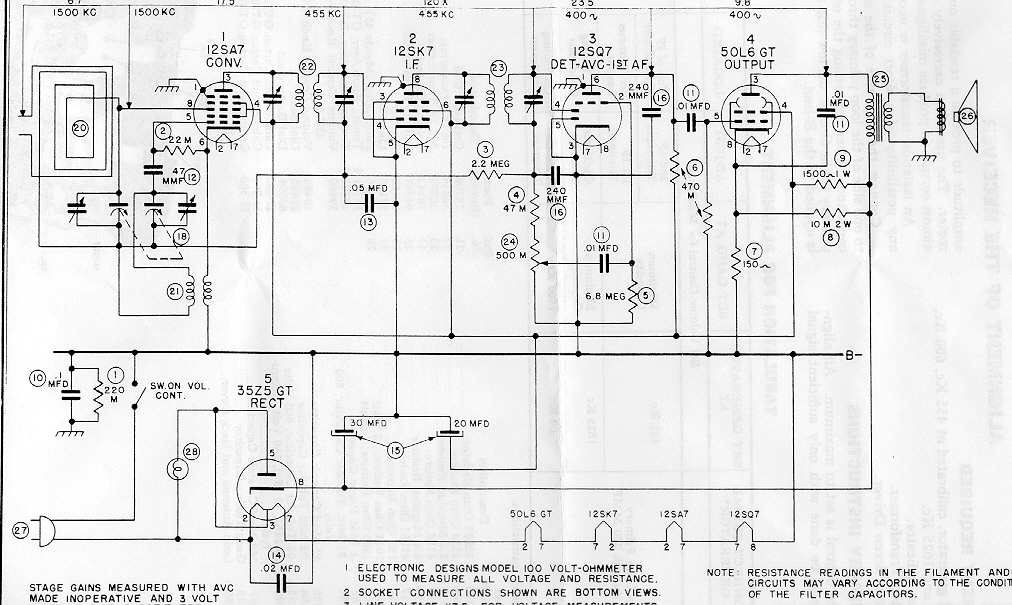
Inside the distinctive cabinet is a very conventional five-tube
AM receiver (see Schematic). As found, the
radio emitted only a loud,
low hum, unaffected by either the volume control or the tuner.
It's working just great now, but the story of how I found the problem
is a bit of a twisted tale.
Electronics, Day One
Loud hums usually point to problems in the
power supply, most often bad filter capacitors,
so my first step was to replace the old two-section filter capacitor
with two modern electrolytics.
That treatment alone will bring many an old hummer back to life.
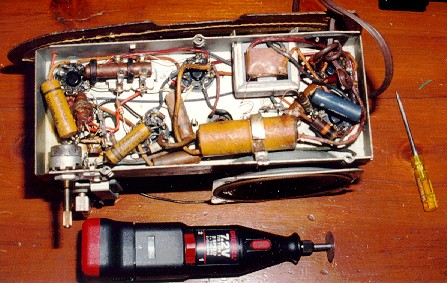
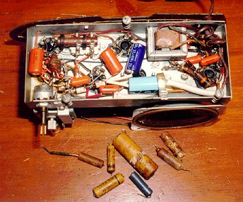
As long as I had the set on the workbench, I replaced all
the other old paper capacitors, too. Click on the images below
to see the chassis before and after the replacements.
Starting with the old filter capacitor, I used a Dremel Moto-Tool
to carefully cut the metal band that held it to the chassis.
This allowed easy removal of the old unit without destroying
the band, which is riveted to the chassis. Some times this band
is mounted with a screw, which makes things a little simpler.
The old metal band provided a handy place to route one of the
replacements, so I left it in place for that purpose.
Some finicky restorers conceal the new capacitors inside the old
paper tubes, making the replacement look more authentic. I have done
that on occasion, but these new filters were too big to fit, so I didn't
bother with that nicety. The radio will work exactly the same, no matter what
it looks like under the covers!
One area where I do take care, however, is in soldering the
replacements.
Some times you may see a sloppily repaired set, in which the old capacitor
leads were simply snipped off at the case end, and new capacitor
leads crudely attached to the old ones. This is a bad idea for several
reasons. Most importantly, it relies on an old connection which might be
bad. If the old connection was shorted against something, or had a "cold solder"
joint, etc., then your new component will inherit that problem.
It's better practice to remove the old lead completely from the terminal
and install the new lead exactly like the original. This takes
more time, since you have to heat the old connection, suck or brush away the
excess solder as needed, snip and/or twist the old lead to get it out,
crimp on the new lead so that it makes a tight mechanical
connection, and finally solder it in place. That sounds harder than it is
in practice. After you've done it a few times, installing the new component
takes only a couple of minutes.
The big filter capacitors must be electrolytics, which have a positive and
negative end. It's important to connect electrolytics the right way. If you
don't, they'll fry and your radio won't work.
The smaller capacitors were replaced with Sprague "orange drops."
Polarity is generally not critical when replacing these guys.
Electronics, Day Two
The hum still continued after the capacitor treatment, however.
When I resumed work the next evening, I double-checked my work
to make sure that I
hadn't accidentally reversed polarity on the new filter capacitors
or made some other silly mistake.
Seeing nothing obviously amiss, I turned my attention to the
GT-051 schematic, which had arrived in that
day's mail. The schematic instantly revealed something that
hadn't been obvious before: the location of the power resistor
in the power supply circuit. It is labeled with number 9 in
the schematic, spec'd at 1500 ohms and 1 watt. You will often find
the power resistor near the filter capacitors, but in this
case it's buried in the upper right corner of the chassis.
You can't see it at all in the photos, but believe me, folks, it's there!
The power resistor is connected directly from pin 4 of the 50L6GT
audio output tube to pin 8 of the 35Z5GT rectifier tube.
If this resistor shorts or loses resistance, it will
pass unfiltered AC current into the audio tube. Another potential
hum-generator is resistor 8, shown directly below 9 in the schematic. This
10,000-ohm, 2-watt resistor connects pin 8 of the audio output
tube to pin 8 of the rectifier. (In schematics of this vintage,
M stands for thousands, not millions. So, the 10 M label by R8
means ten thousand ohms, not ten megohms. Elsewhere on the
schematic, you can see MEG used to represent millions.)
I'll replace both resistors as soon as a fresh supply of spares
arrives in the mail. Resistor R9 has a somewhat overheated
look, and it is actually a 1400-ohm unit, according to its
color coding, not 1500 ohms as specified in the schematic.
Perhaps a previous repairman substituted a "close-enough" component
because that's all he had on hand. In any case, bringing the radio
back to spec shouldn't do any harm.
While waiting for my next parts
shipment, I'll double-check the values of all the small capacitors against
the schematic. None of their values looked outlandish when I was working,
but it never hurts to check. Any tube radio that was used regularly probably
had a few paper capacitors replaced in the past, and old-time repairmen
were human, just like us.
Electronics, Day Three
The next morning, I traded a little mail with Walter Heskes,
the designer of this website's construction projects and
an experienced repairman. Looking at the schematic, which I
had already posted on the site, he also recommended checking
resistor R6, the 470K unit running from pin 5 of the 50L6GT
audio tube to the radio's B- line.
That evening, a check of my capacitor replacements revealed no
mistakes, so I resumed the search for the original cause of the hum. With the kids safely tucked
in bed, I first made a very close examination of every connection
and wire under the chassis. Perhaps I, or some previous repairman, had
accidentally dripped solder somewhere, or nudged a wire out of
position so that it shorted against the chassis or another connection.
Finding no obvious shorts, I also used my multimeter to check for
continuity between a number of connecting points. Some times a wire may
be cracked inside its insulation, so that it doesn't conduct properly,
although it looks fine from the outside. Sloppy
soldering can also result in a "cold solder" joint that doesn't work
electronically.
This check revealed more good news, of a sort. The radio has
many working connections and excellent
solder joints. The bad news is that it still hums like crazy!
Power resistor R9 was previously tagged as a potential trouble source,
so I removed it from the chassis and tested its value with the multimeter.
The reading was 1.8K, somewhat higher than wanted, but not so far off that
it could be causing the hum. Nevertheless, just to eliminate it from the
equation, I formed a temporary replacement by soldering two
3.3K, 1/2-watt resistors in parallel, and putting that back in the
circuit. (Wiring two resistors in parallel halves the resistance value and
doubles the wattage, so the test unit's value is 1.6K at 1 watt.)
Still no change, although I noted that the replacement resistor got
very hot when under full power. It wasn't going up in smoke, but
it was hot enough to burn your finger, indicating that it would probably
melt down eventually. The power resistor wasn't causing the hum,
but there's definitely something haywire in the power supply.
I also unsoldered and checked the values of R6, R7, and
a few other resistors. One or two had drifted
a bit in value, but none had failed to the point where it could cause
this gross problem.
The audio output transformer, labeled 23 in the schematic, plays
a role in the power supply as well as audio output. These are cheap
items, and I had one on hand, so, "out with the bad, in with the good."
Now the radio has a nice, new transformer, but it still hums.
You might wonder why I replaced the old transformer instead of simply
testing it. Well, by the time you have unsoldered the old leads, it's
approximately the same amount of work to install a new one or
reconnect the old one. I plan to use this radio, not merely
display it, so popping in fresh components wherever convenient
is not a bad thing to do. And I'll save the old transformer for
a future project or emergency replacement.
All right, it's time to get serious. This evening, I'm going
to measure the voltage at every pin of
every tube, writing down each value for later comparison against the
values given on the schematic.
Before measuring voltages, however, I decided to check the tubes.
I had previously done a quick substitution test, replacing
the tubes in the radio with known good tubes of the same type.
That test showed that the hum wasn't caused solely by a
tube defect, but it didn't tell me much about the old tubes
themselves.
Quickly reading the labels on various radios in the house,
I found an RCA Model 8-X-541
that uses exactly the same tubes. It took only a few minutes
to pop the tubes out of the Farnsworth, substitute them in the RCA,
and confirm that every one worked fine. You can check tubes with
a tube tester, of course, but many
repairmen feel the best test of all is whether a tube performs
well in an actual radio.
Reinstalling the old tubes in the same sockets was easy, because a
previous owner had thoughtfully written down the tube numbers
in pencil next to each socket in the chassis. (In hindsight,
this was a critical moment in our quest for the cause of hum,
but I paid very little attention, already thinking ahead to
the next step.)
On to the tube voltage measurements. We know that all of the tubes
are good, so any pecularities in voltage readings should help to identify
problems in other components. The schematic says that voltages must be
measured using an input voltage of 117.5 volts. I have a
variac (variable transformer) that's ideal for providing a precise line
voltage. Using my multimeter to double-check the variac's output,
I set it to exactly 117.5 volts before plugging in the radio.
To take voltage measurements, I clipped the multimeter's negative probe to
the B- line on the radio. On many radios, including this
one, the chassis is not at the same potential as the B- line, so it's
important to take voltage readings from B- rather than the chassis itself.
Taking measurements from a live radio chassis should be done with great caution.
For safety's sake, you should never touch your fingers to any part of
the radio while under power. In fact, it's best to do this and
other repair operations
with the radio plugged into an isolation transformer, to prevent any
possibility of a fatal shock. You also need to use care to avoid accidentally shorting connections when you're moving the probe from pin to pin.
The readings verified that
something was seriously wrong in the power supply.
The 35Z5GT values showed that that the rectifier tube was working
decently. But farther down the line, things didn't add up at all.
For example, pins 4 and 5 of 12SA7 should read about +84v DC,
but the actual reading was 32v DC, less than half the spec'd value.
And some other readings were even farther off.
The radio still isn't fixed, but we have a lot more data to work with.
I retired for the night, setting aside the chart
for more analysis the next day.
Electronics, Day Four
The next morning, I emailed the voltage readings to Walter Heskes,
who immediately noted that the filament voltages did not add
up. Here is his reply:
Congrats on the excellent job of documenting the voltages observed throughout this set.

Recall how we like to work our way up from the cellar in these sets; that is,
look at the power supply in the boiler room and see if the furnace is doing its
job.

Well, the first item we checked was the difference of potential between pin 8
of the 12SQ7 and B-. If you look at the diagram, you can see that they should be
at the same value since they are directly connected with no intermediate
components. Indeed, the spec'd value is 0 and you can see why. So, imagine our
surprise when we saw that you read 31 VDC at that point. Whew!! B- is operating
with 31 VDC. No wonder things are messy. Something really is out of whack here.

Working backward through the filament string, each tube should draw the
voltage specified in its name; that is, 12SA7: 12 volts, 12SK7: 12 volts,
50L6: 50 volts. You add backwards as you read voltages upstream of B-.
12 + 12 + 12 + 50 = 86 and, indeed, the specs call for 84 VAC at pin 2 of the
50L6 with a 50 volt drop across the tube filament. So, your readings on
the 50L6 look okay as they are close to the spec'd values. You could adjust
your variac to obtain exactly 84 volts at pin 2 and repeat your readings,
next time. That would give you a reference value with which you can compare
the downstream readings.

Now, whoa! Look at pin 7 of the 50L6: 28.6 volts. Okay. Fine. But, pin 7
is directly connected to pin 7 of the 12SK7 and the voltages should be exactly
the same at both points. But, look at your readings: 42mVDC at pin 7 of the
12SK7. GAAAHHHHH!!!!!

Please check that wire.
That evening, I sat down at the workbench to thoroughly test the filament
path. Starting at pin 7 of the 50L6GT tube, I again checked the wire leading
to pin 7 of the next tube for continuity. Still good, just like before.
Hey, wait a minute! The schematic says that tube is 12SK7, but I could
swear that the number written on top of the chassis was 12SQ7.
Turning the radio over, I check the printing on the tube and the
number scribbled next to it. Sure enough, both say 12SQ7.
What's going on?!? Uh-oh. A very big, very embarrassing
light bulb goes off. Is it possible
that somebody mixed up the tubes in this set and then wrote down wrong
numbers next to them? Could anybody be that dumb?
Comparing the schematic to the connections seen under the chassis,
it took only a few seconds to answer that question. Sure enough, the
12SQ7 was out of place. 12SK7 belonged in the socket
labeled 12SQ7, and vice versa.
I reversed the tubes and turned the set on. It worked like a champ!
Great sensitivity, nice tone. Nothing wrong at all. I packed up for the night, in a much better mood than the previous evening, but silently
cussing out the anonymous "repairman" who had mixed up the tubes.
Electronics, Day Five
In the next day's mail, I got a care package from AES containing
some new resistors and other goodies. I installed the new
power resistor (R9) and took a moment to erase the scribbled
tube numbers from the chassis.
I guess I'll never know exactly how the tubes got swapped. In the end,
it doesn't matter. The radio works well now, and in the course
of tracking down the problem and exchanging mail with Walter, I
got some great advice about diagnosing power supply problems.
I learned an even more basic lesson, too: Assume Nothing!
Because tubes are so often found in the right sockets, it's
easy assume they must always be so. But it never hurts to check
the obvious.
In hindsight, the very first time that I saw the 12SQ7, I should have
noticed that it was out of place. In an "All American Five"
superheterodyne radio of this type, the intermediate-frequency
(IF) amplifier tube (here, 12SK7) must come earlier in the signal path
than the detector tube (here, 12SQ7).
But when you're focusing on some other problem, it can be easy to
mistake the forest for the trees!
Now that this little Farnsworth plays as good as it looks, it
has joined the "honor guard" in our home, those few sets that
are used and seen (and enjoyed!) every day.
|
