Grundig Model 940W MW/LW/UKW Radio (1950?)


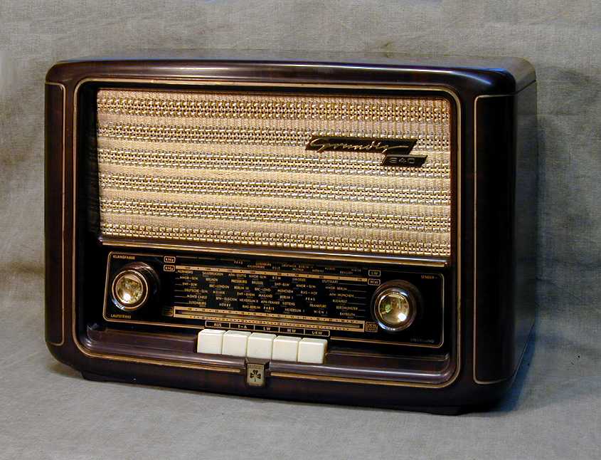
Unmistakeably European, this Grundig 940W could almost serve as a template for the classic German tabletop radio.
The hallmarks of this look are the upright, comparatively shallow cabinet; a generous speaker mounted over a slide-rule type dial;
side-mounted knobs for tuning, volume and tone; and a set of ivory pushbutton switches below the dial for changing
bands and functions.
Description
The first photo shows the restored radio.
This is basic three-band radio, covering MW (broadcast band), LW (long-wave band) and UKW (FM band),
and equipped to connect an external phonograph turntable (Tonabnehmer).
It uses only four miniature tubes: types ECH81, EF41, EBC41, and EL41. It's rather impressive that the designers
could get decent AM/FM performance from only four tubes. The hefty speaker in an ample cabinet contributes
to good fidelity, and nobody could complain about a lack of volume, although the tone has too much
bass for my taste.
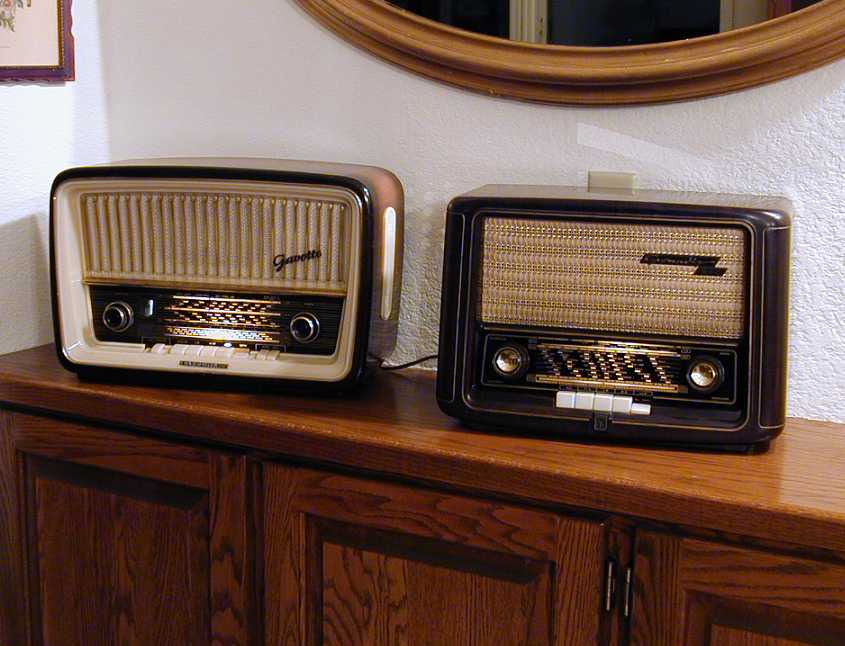
The next photo shows my 940 in a "radio party," playing its heart out next to its more sophisticated German cousin,
my Telefunken Gavotte.
Although these two radios are similar in appearance, it's not really fair to compare them side by side.
Nobody would expect the little Grundig to match the more costly and feature-laden
Telefunken. Still, considering the simplicity of its design, the 940 is a respectable performer.
A better-quality Grundig from this time is the model 960, which adds
shortwave reception and three speakers rather than one, not to mention other features.
If anyone has a nice original model 960 for sale, please send me some email.
(The Grundig company recently issued a modern reproduction of the 960, which is widely
available, but I would not recommend it to collectors. For the same price, you can buy
an authentic 960 and restore it. Why settle for a fake, when you can get the original?)
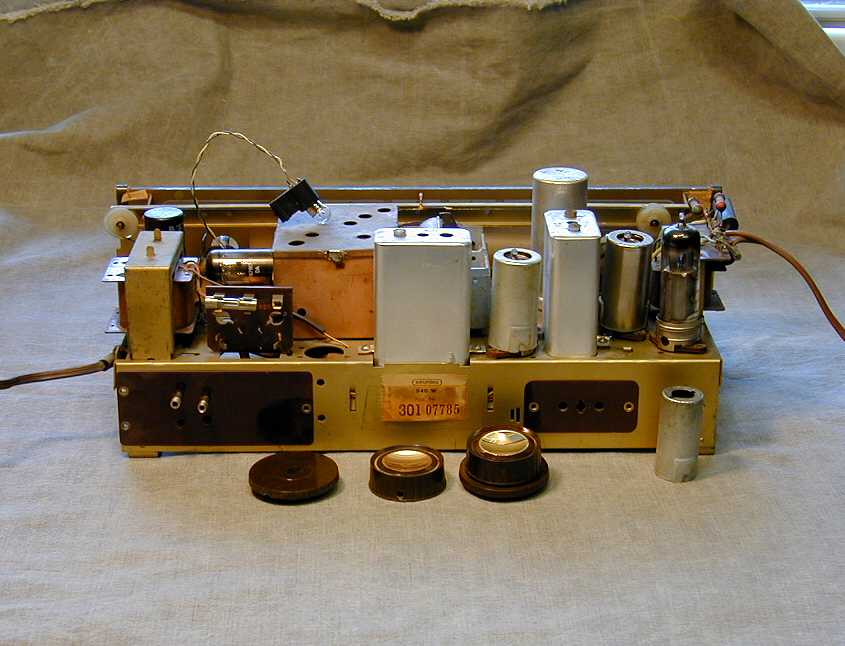
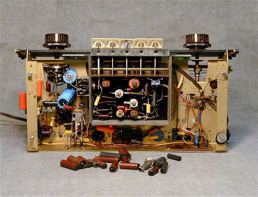
Here is the chassis in a rear view, before I had started restoration. The brass inserts in the
two main knobs had been badly tarnished, but they were easily polished to a brilliant sheen.
A previous owner
had jammed American metal tube shields onto the three rightmost tubes. One of them had been
removed from the EL41 audio tube at the time of this photo. None of the shields appeared to fit
correctly, and my Philips 4-tube set has no shields at all, so I put these
into the parts bin for a future American radio project.
Most European radios have some provision for switching between different supply voltages. Some
use a switch on the back of the chassis, others require a bit of rewiring. This set employs a two-position fuse
in an elegant alternative. Look at the left side of the chassis. In the left position, the
radio accepts a .4 amp/120v fuse for US operation. In the right position, it accepts a .2 amp/220v fuse
for European operation.
The back side of the chassis has a few connection points. To the left are four antenna terminals.
The leftmost pair (top to bottom) is for an external AM (i.e., MW/LW) antenna at the top, with
an external ground at the bottom. The rightmost pair is reserved for a standard FM dipole antenna.
The three-pronged jack on the right rear is for an external phono turntable.
When I cleaned up the chassis, I was initially puzzled by a black can-type component which you can
see peeking over the top of the left-mounted transformer in the previous picture. Similar in size
and shape to a black metal-cased tube, it didn't seem to match with any component in the
schematic. When I turned the set over and traced the wiring, I discovered that it was the
power supply rectifier. Solid-state rectifiers of this vintage are often unreliable,
so I replaced it with a modern silicon diode, leaving the original in place for appearance's sake.
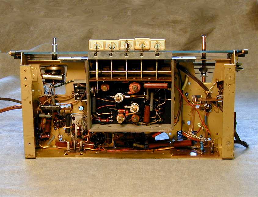
The next photos show the radio before and after I replaced the paper and electrolytic
capacitors (see How to Replace Capacitors in Old Radios).
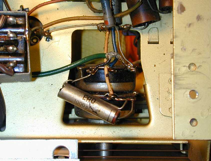
A couple of capacitors looked a bit unusual to my American eyes. Here is a closeup of one of them. Notice the extra
lead at one end of the capacitor.
I initially thought that this might be a dual capacitor (two capacitors in one shell), something I had found
when restoring my Philips Philetta. The label gave only one value, however. It turned out
to be a single capacitor, with an extra lead connected to an outer shield. I didn't have any such capacitors
on hand, so I tried replacing this with an ordinary 1000-pf capacitor, which seemed to work just fine.
About halfway through the restoration, the dial string broke, so I also replaced that. This stringing is a little unusual, using
a pair of opposing cords on each side of the tuning capacitor. One of the cords is actually a thin metal cable. The other one,
made of fabric, had frayed through and broken at the tuning knob shaft.
With that, the restoration was complete. The 940 is not the most sophisticated radio ever made, but it makes a nice addition
to my small stable of European receivers. Other European brands in my collection include Blaupunkt, Nordmende, Philips, Rekord,
Roberts, Schaub-Lorenz, and Telefunken.
|