|

Build a Portable AM Radio Transmitter
After we published the original Li'l 7 AM Transmitter plans,
fellow experimenter Scott Todd sent us information about his design for a similar
portable, battery-powered transmitter.
Scott calls this one the "A-1 Minicaster." Details appear below. If you have questions about
this project, kindly contact Scott Todd at sat@nwc.edu.
-----Original Message-----
From: Scott Todd
Sent: Wednesday, April 12, 2000 8:58 AM
To: Walter Heskes
Subject: A-1 minicaster
I noticed that you have yet to get around to developing a battery
operated part 15 transmitter for swap meets (or if you have, it's
not on the net.) Well, I decided to take matters into my own hands
and did one myself.
Actually it was nothing more than a variation on a converter
circuit in a farm radio using a 1A7 (hence the name A-1 Minicaster.)
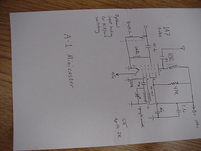
Since I'm no computer genius and don't own a scanner, I'll have to
describe the schematic. Should be simple enough- Pins 1 & 2
[base shell and A- respectively] to gnd. Pin 3 [plate]- RF choke >1mH
(will be replacing with tuned circuit for better performance and lower
spurious output) to B+, and .01 to antenna terminal. Pin 4 [screen]
through 47K to B+, and .05uF cap to gnd. Pin 5 [osc. grid]- 220K to
gnd, and .001u cap to secondary of osc. coil; other end of same to
gnd. Pin 6 [osc "plate"]- primary of osc. coil to B+. Pin 7 through
1/2 DPST sw. to +1.5v. The other half of the DPST switches B+.
Cap grid- 1M ohm to gnd, and >/=.05uF cap to input jack (RCA).
Additional touches- NE-2 neon indicator across B+ for power on;
a low resistance (8-24ohm) that can be switched in or out as needed
across the RCA jack for proper loading of audio source, such as
when using a small pocket size tape recorder speaker output jack
for source of programming.
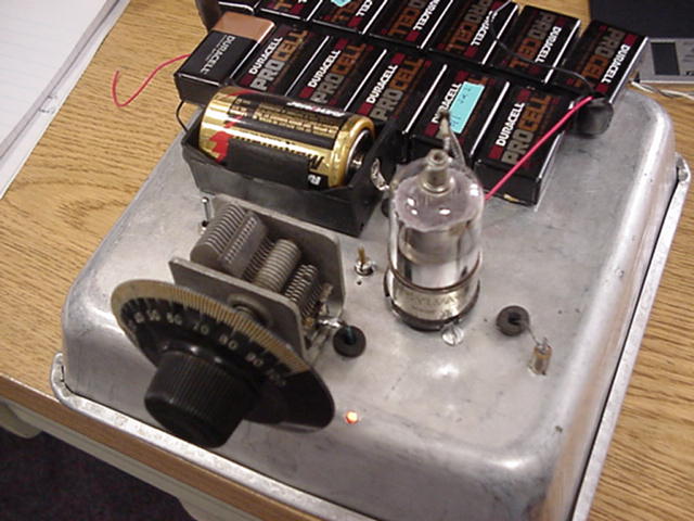
Built mine on an old cake pan that developed holes and was no longer
useable.
Scott Todd
N0BST
-----Original Message-----
From: Scott Todd
Sent: Wednesday, April 26, 2000 8:24 AM
To: Heskes, Walter M.
Subject: RE: A-1 minicaster
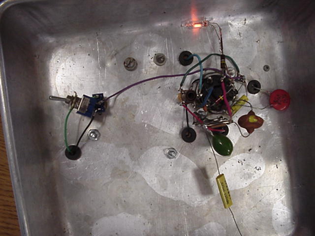
Here's the pix of the A-1 minicaster, top and bottom plus schematic. I
didn't have a DP switch, so I had to kluge a second SP underneath for the
HV. Note the neon indicator for HV-on. Small cap to osc grid is .001
(noticed it was too small to read on schematic.)
This radio construction project, including all descriptions, diagrams, photos, and the underlying electronic design, is published here for the noncommercial use of radio hobbyists. You may print and reproduce these project instructions for your personal use. Commercial use of this material is strictly forbidden.
|