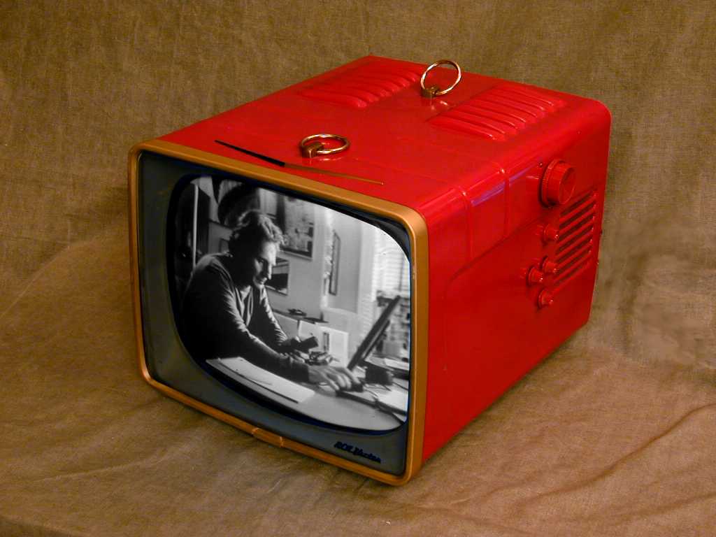
RCA Model 14-S-7070G Television (1957)


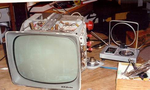
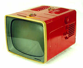
What great colors for a TV—lipstick red with gold trim! This 14-inch black-and-white set caught my eye during a trip to northern Washington. I call it my '57 Chevy TV, a real design classic.
As with most tube portables, it would be more accurate to call this one a "luggable." Its dimensions are 14.5 by 12 by 16 inches deep, a nice size for a tabletop, but not conducive to frequent moves.
The gold rings on the top are mounts for a thick leather carrying strap. My set is missing the strap, which was probably discarded after it broke.
I didn't know exactly when this set was built until Ed Ellers sent me this note regarding the model number:
In the 1951-1956 model years the scheme was as
follows: the first two digits before the letter(s) were
the overall screen size, the letter(s) indicated the type
of set, and the first digit after the model number gave the
model year. The next digit after that was the level of that
model (starting with 0), and the last digit was the specific
cabinet style. So for your 21T227, 21 would have been the CRT
size, T would have meant a standard TV model (D stood for
Deluxe), 2 meant the 1952 model year, the next 2 meant the
third level of 21" standard TV models, and the 7 was the
cabinet style.

In the 1957-1959 model years this scheme was modified with
a fourth digit indicating the cabinet finish. Thanks to Ed
Reitan (http://www.novia.net/~ereitan/), I found out that
0 was cherry (as in your 14" set), 2 ebony (a.k.a. black),
4 was maple, 5 was mahogany, 6 was walnut, 7 was either
blonde or limed oak, 8 was bleached birch and 9 was maple
or light cherry. In the 1960 model year this was modified
to put the year digit before the letters, and a different
set of letter codes were used; starting in the 1961 model
year the letter codes were changed again to the same system
RCA uses today, as follows:

A B&W portable
B B&W table model
C B&W console
D B&W combination
E color portable
F color table model
G color console
H color combination
I B&W Service Company model (for hotels, schools, hospitals, etc.)
J color Service Company model

In the 1964 model year the screen size designation was omitted
and all TV model numbers that year began with 14. From
1965-1980 TV model numbers had a model type letter, a year
letter and three digits; from 1981 to the late 1980s they had a
model type letter, a year letter, a third letter (either R or C)
and three or four digits; starting in the late 1980s (I'm not
sure of the date) RCA TV model numbers have had one or two model
type letters, two digits for the screen size and three digits
for the model.

Ed Ellers
Electronic Restoration
This television "almost worked" as found. The screen lit up, and the sound came through just fine. There was only one thing missing—a video image!
Although I had restored many radios at this stage, this was my
first TV project. The TV sat on the shelf for quite a while.
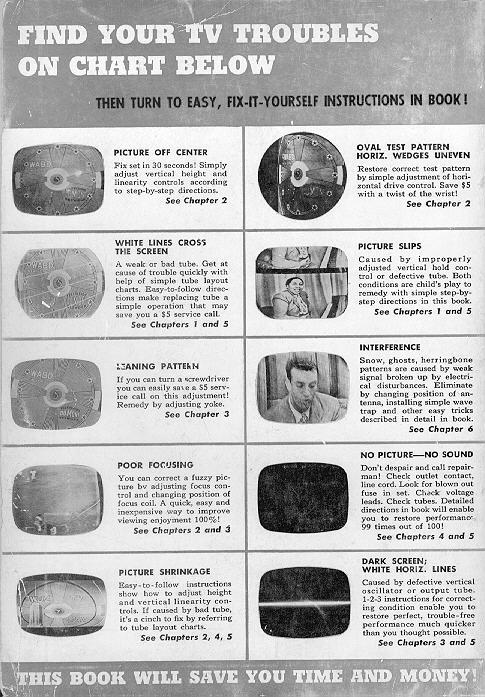
Then I ran across a cute 1950's book called How to Adjust and Service Your TV Set.
Don't you love that cover photo of Lucy and Desi? Here's the thumbnail diagnostic guide from the back cover.
Written for non-technical TV owners, the book contained considerably less information than I had hoped. It explained the basics of television theory, but it didn't go beyond simple adjustments and helping you decide which tubes to replace.
Still, some information is better than none. According to the book, my TV's symptom indicated a problem in the video section. The set's label identified its video tubes, and I happened to have replacements in my stash of known-good tubes.
Before substituting any tubes, I removed the chassis from the cabinet, brushed away all the dust, and gently powered it up using my variac, to make sure it didn't have any serious shorts.
Seeing no smoke and smelling no bad smells after a few minutes of operation, I turned it off, popped in the replacements, and tried it again.
Caution! TV repair is more hazardous than repairing old tube radios, which can be dangerous enough. A live chassis has elements carrying high voltage—more than sufficient to cause serious injury or death. Unless you have experience in working around high-voltage electronics, I'd advise you to leave the
job to someone else.
With some fresh tubes in place, I saw an instant improvement. In addition to sound, there was a pretty good image, even using a rabbit ear antenna in our lousy reception area. In the photo below, my camera's flashbulb washed out the image pretty badly, but you still may be able to pick out the character Phoebe from the TV show Friends.
Although the picture now had decent contrast, brightness, and resolution, that concluded the good news portion of our broadcast. After about twenty minutes of operation, when the set reached full operating temperature, the picture began to roll, and no adjustment could stabilize it.
Considering where I had started, with no image at all, this was a major improvement for one night's work. I powered the set down and started to compile my shopping list, including a complete schematic and replacement capacitors. In the next photo, the circles identify a couple of old wax paper capacitors that look very
"toasted."
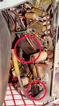
Note that you can't determine the health of a capacitor just
by looking at it. Paper capacitors are typically all bad, and
I replace them all as a matter of course when restoring an old
tube radio. See Replacing Capacitors in Old
Radios.
The chassis of this set carries a dense mat of components, many of them crammed down near the neck of the picture tube. To reach all those paper capacitors, I may need to pull the picture tube.
January, 1998 update
Over the holiday break, I found a little time to work on this set, replacing several paper capacitors, including the two most obviously toasted caps, plus some others associated with vertical circuits.
For this work, I followed the Sams service manual, which you can download from the Early Television Foundation
archive (Sams Set 354, Folder 16).
All of the paper capacitors need to be replaced eventually, so I'm going to plug away at replacing them. Next in line are the filter caps in the power supply, whose B+ voltage reads about 5%-10% lower than the ideal, even after I installed a new 5U4GB rectifier tube. The TV still goes into a steady vertical roll after running for about half an hour.
June, 1998 update
The vertical roll problem has been fixed! Acting on advice from an experienced TV repairman, I used a can of spray coolant to isolate the component that was causing the roll after heating up. It was a capacitor C54 in the vertical section. Funny thing is, I had already replaced C55 and C56, which lie on either side of C54 on the chassis. In the course of recapping the whole set, I eventually would have solved the mystery by brute force, but it was more fun to successfully diagnose the problem and see it go away.
The TV is in pretty good working condition now. All but one or two of the old paper capacitors have been replaced. I still intend to investigate the power supply, but we're moving to a new house this summer, so the project may have to wait.
April, 2001 update
All of the old paper capacitors have been replaced and the TV plays well.
I'll try it out a few more times and decide whether it's worth replacing the last
two electrolytic capacitors.
October, 2005 update
I finally reopened the set and replaced the two large electrolytic capacitors in the power supply.
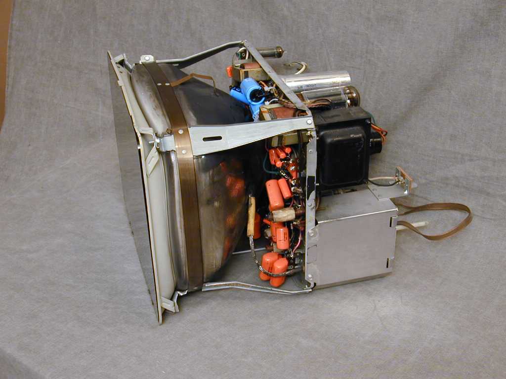
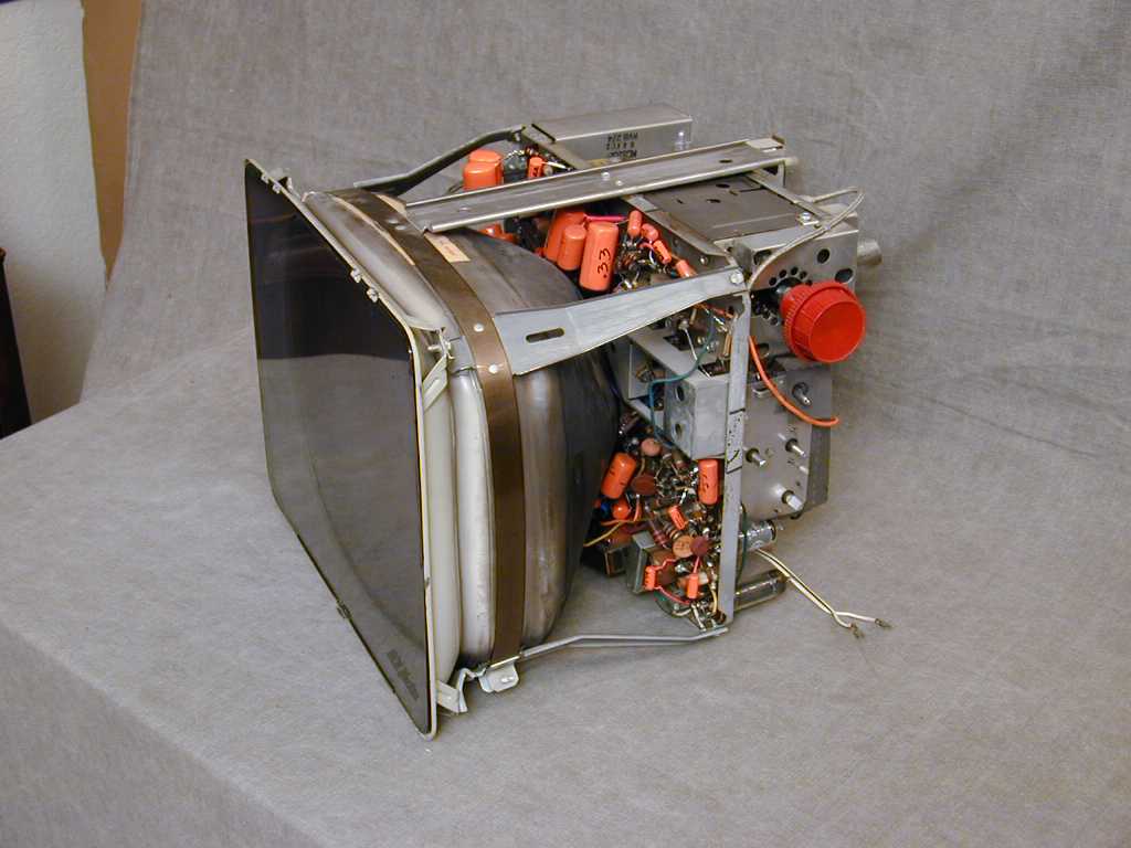
It worked fine with the originals in place, but you can never be too careful. Here are two photos of the
recapped chassis. The blue capacitors are electrolytics and the orange ones
are replacements for the old paper caps.
This is not an easy TV to work on. Although it's larger than my
little metal-cased RCA 8-PT-7012, its components are packed tightly,
as you can see. If you're looking for a beginning TV project, I'd start
with a different model whose chassis is not as cramped.
This snapshot shows the TV playing on October 3, 2005. The scene
is from the movie Love, Actually.
Final Thoughts
Since I originally created this page, this little TV became a TV star of sorts. With my permission, a company called Educational Video Network, Inc. (1401 19th St, Huntsville, TX 77340) used this and several other of my images in an educational video called "The Chip That Changed the World." The video chronicles the development of modern integrated circuits. In one segment, the very first image shown in this page is morphed into a modern, big-screen TV—pretty cool!
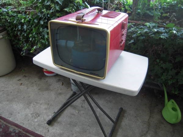
A year or two after that final photo, I sold this TV to a fellow collector, but I never forgot this red and gold set's distinctive
appearance. In 2016, another one showed up for sale in a local ad, and I couldn't resist. Here's a photo from
that craigslist ad and a photo of my second 14-S-7070G after restoration:


You can read about restoring that set in a second article.
Will I ever restore a third one? Probably not, but it was fun to revisit this
chassis nearly 20 years later.
|

