|

Adding an S-Meter to a Hallicrafters S-38 Radio
The Hallicrafters S-38 is a very popular
shortwave receiver and a great performer for the money. One feature it
lacks, however, is an S-meter to show the strength of the incoming signal.
This page shows how to add an S-meter to your S-38. The
total cost of the project is around $10 and you should be able to complete it
in one evening. Thanks to Walter Heskes for constructing a prototype and
providing an updated schematic. Construction details and photos of Walter's
prototype appear at the end of the article. The first portion of this
article is excerpted from an original Hallicrafters service bulletin.

"S" meter circuits for use with the Hallicrafters Models S20R, S40, S40A, S40B, SX62, S77, S85, etc., Communications Receivers.
In answer to many requests for an "S" meter circuit which could be installed in the Hallicrafters model S-85 and similar receivers not originally equipped with a built in "S" meter, we are pleased to announce herewith a kit of parts that is adaptable for installing such a meter not only in the S-85, but also models S20R, S40, S40A, S40B, SX62, S77A, etc.
Because the plate current of an RF or IF stage, controlled by AVC, varies inversely with the received signal strength, it is only necessary to measure the plate current of such a stage to get the relative indication of the signal strength. Provision should be made to balance out the residual plate current to "zero" the meter for calibration purposes. The basic circuit of the Hallicrafters "S" meter kit for performing these functions is shown below:
Best results are usually obtained by inserting this circuit in the plate return of the first RF tube. In some receivers, good results may also be obtained in the plate return of one of the IF tubes, although generally speaking, the RF stage is the more sensitive. Whatever the stage chosen, the following conditions must be met:
- The stage must be controlled by AVC.
- The tube's screen current must not pass through the meter.
After the meter is installed in the receiver it will be necessary to make the following adjustments. The setting of the meter should also be checked occasionally, after long periods of use:
- Mechanical zero set: Turn set off. With pointer adjustment screw on front of meter, set pointer on last calibration mark on right hand side of meter scale.
- Electrical zero set: Set the RF gain or sensitivity control to maximum (full clockwise) position; AVC on; noise limiter (ANL) off; BFO off (CW-AM switch to AM); selectivity to broad or sharp (no xtal); turn up volume (AF gain) control. Turn set on and allow to warm up for at least ten minutes. Tune to a quiet spot on the dial, preferably on one of the higher frequency bands. Do not tune in a signal. Remove antenna and short the antenna terminals to ground. With zero set control (part #25-022) set meter pointer to "S" unit zero on left hand side of meter scale. Remove short on antenna terminals and reconnect antenna.
If difficulty is encountered in obtaining electrical zero, variation in the basic circuit as shown below may prove helpful.
Inability to obtain electrical zero may result from several causes:
- Weak or aged tube in "S" meter stage.
- Cathode resistor in meter stage is wrong or has changed value.
- Some receivers are designed leaving a residual AVC voltage applied to the tubes. In this case, with sets equipped with an AVC on-off switch, the meter may be zeroed with the AVC off. The RF gain control on the receiver may not reach absolute zero resistance at maximum gain position (design function). With the set out of the cabinet, this may be checked by shorting out the RF gain control. In this case, short out the RF gain control and zero set the meter. Remove the short from the gain control and observe and record the reading. This reading is the true electrical zero and should be used for any future resetting of the electrical zero.
Hallicrafters "S" Meter Kit, Part No. 59X031
Includes:
- Meter calibrated in "S" units; 0-5 ma movement (part no. 82-283).
- Control, electrical zero set; 500 ohms (part no. 25-022).
- Resistor; 82 ohms 1/2 watt (part no. 23X20X820)
- Resistor; 330 ohms 1/2 watt (part no. 23X20X331).
A Suggested Circuit and Installation Instructions for Installing an "S" Meter on the S-38 Series Receivers
An "S" meter installed according to the above diagram will have one lead connected to B- and in this type of receiver B- is connected to one side of the AC line. In order to prevent a hazard, an isolation transformer (STANCOR type P-6410 or equivalent) must be used. In addition, the meter terminals "A" must be completely covered and the connecting lead "B" must be the rubber covered 115 volts AC type.

Construction Details
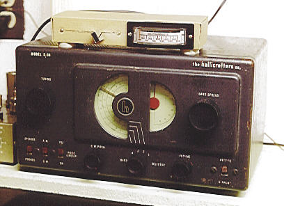
Walter Heskes built an S-meter for his S-38 and kindly provided some photos as well as an updated schematic.
The following photo shows the completed meter sitting atop Walter's S-38. Click the thumbnail image for a larger view.

The prototype uses a slider-type variable potentiometer. It is housed in a small cardboard box
about six inches wide.
The next photo gives a peek inside the project enclosure. Very few parts are required, as you can see!

Here is the schematic diagram for this project:
Walter's prototype uses a 1-milliamp meter instead of the 5-milliamp meter
specified in the original plans. You can buy such a meter for $7.95 from
Antique Electronic Supply,
part #S-PMD1MA. A 2K-ohm audio potentiometer is
available from All Electronics, part #ASP-2K.
Note: A 2200 ohm, 1/2 watt resistor is added in series with the meter to
lower the current in the circuit and prevent overloading the meter. The 2K
potentiometer is used to align the needle with the zero value on the dial
scale when you calibrate the meter to a null signal.
Resistor R4 (390 ohms) is part of the S-38's circuitry. It is mounted on the
Receive/Standby switch at the front of the chassis and it connects to the cathode
of the 12SK7 (1st IF amplifier tube). The three new components are connected in
parallel across R4 as shown in the schematic.
This S-meter is a "reverse meter." That is, the needle
rests all to the way to the right at zero signal and deflects toward
the left as you tune in a station.
Please observe normal safety precaution when working on the chassis
of any tube radio. Unplug the set when you're working on it, and make
sure that all wires going in and out of the receiver are well insulated
and secured. As mentioned in the Hallicrafters document above, an
isolation transformer is a very good thing to use with any AC/DC radio.
Enjoy!
This radio construction project, including all descriptions, diagrams, photos, and the underlying electronic design, is published here for the noncommercial use of radio hobbyists. You may print and reproduce these project instructions for your personal use. Commercial use of this material is strictly forbidden.
|