Zenith Model R-7000-2 TransOceanic Radio (1981)


Last of a proud lineage, the Zenith R-7000 TransOceanic is a study in contradictions. Produced from 1979-1981, it
was the most powerful and sophisticated TransOceanic of all, employing integrated-circuit technology with modular printed-circuit boards,
while eliminating several weaknesses of previous solid-state models.
Yet the R-7000 was a commercial flop, eclipsed by
smaller, easier-to-use Japanese imports. Originally priced at $379.95, the R-7000 was discounted to an ignominious
$50 by the time the party ended.
It remains a favorite of collectors, however. Produced in small numbers for only three years, it is
one of the scarcest TransOceanics. Only 75,000 were produced, as compared to several hundred thousand of
the tube models. Moreover, as the last of its line, the R-7000 has an appeal similar to the first TransOceanic, the
7G605 Clipper, for anyone wishing to fill out a TransOceanic collection. Most importantly,
it's an excellent portable multi-band receiver, with features and performance that reflect Zenith's three decades
of TransOceanic development.
Description
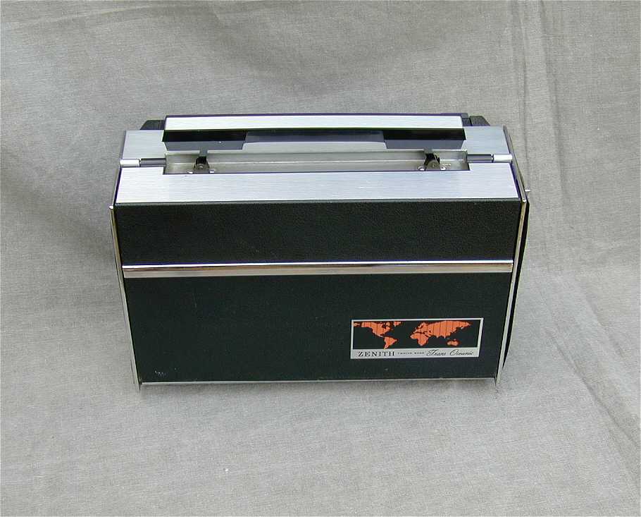
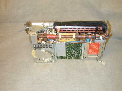
The first two photos show the R-7000-2 open and closed.
This is a twelve-band receiver. Like its most recent predecessor, the 3000, it covers FM as well as BC (standard broadcast)
and shortwave bands. Unlike all previous TransOceanics, this set offers continuous coverage throughout the
shortwave bands rather than limiting coverage to the most popular frequencies. It also covers VHF broadcasts
for marine, aviation, and weather broadcasts.
The R-7000 added an SSB (single-side band) mode and a Squelch control, features useful for listening
to amateur transmissions.
It also had a bandwidth switch, allowing you to choose wide bandwidth for better fidelity or narrow bandwidth
for separating weak stations in crowded frequencies.
These features are more typically found on high-powered
communications receivers.
There were three versions of this TransOceanic, produced in the years 1979 (R-7000), 1980 (R-7000-1), and 1981 (R-7000-2). Mine is the final, and
most desirable version, model R-7000-2.
While all three models share the same basic features, the first two suffered from a bad tuning drive. In models R-7000 and R-7000-1,
which had chassis 2WKR70, the tuning drive used a rubber belt, which tended to stretch or break, giving you sloppy
tuning or no tuning at all. In the final version, model R-7000-2, which had chassis 2WMR70, the tuner is entirely gear-driven,
providing greater precision and reliability.
You can get R-7000 belts from various online sources. Since those sources
change from time to time, I'll let you do an Internet search rather than
provide a link that may be out of date in a few weeks.
The R-7000 series also corrected a few problems that plagued earlier solid-state TransOceanics. It eliminated the
cheap chrome plating, which frequently corroded and blistered over the years, as well as the fragile antenna concealed inside
a hinged carrying handle. The R-7000 has a robust, one-piece handle that pops up from the cabinet top when needed. The antenna
pops up separately and is located behind the handle.
Another pesky feature of the model 1000 and 3000 TransOceanics was the hinged, two-piece front cover. Although clever in its
way, the cover was easily broken. It is not unusual to find those TransOceanics with missing or half-missing covers.
When lowered, the large cover also stuck out a long way from the cabinet, making it a dirt-catcher as well as
a frequent accident victim.
In the R-7000 series, the cover is also in two pieces, but the
upper part swivels upward, as in the 8G005,
500, and 600 series TransOceanics. The lower cover swings down, as in all models
except the 500 and 600 series, and it also slides back into the case when fully lowered. This limits the radio's footprint and helps
to protect the cover when open.
Zenith also improved the battery compartment for this model. In earlier solid-state models, leaking batteries could drip
corrosive material into the metal cabinet. In the R-7000, the batteries are completely separated from the chassis,
held in a two-part back made of rugged plastic. This battery
carrier is also impossible to lose, unlike the 1000 and 3000
battery cases.
In appearance, the R-7000 departed dramatically from its earlier siblings. Gone was the "chromy" 1960s look of models 1000 and 3000.
The new TransOceanic was outfitted in black brushed chrome, and dark orange. The side panels were encased in black leather.
The R-7000 has two small needle meters at the upper right. The rightmost meter is used for centering
when tuning in FM stations. The other meter does double duty, indicating signal strength during normal
operation or showing the battery strength when you press a switch on the front control
panel.
The R-7000 provides FM stereo sound when you plug stereo headphones into the front jack. When listening to
the single speaker, you hear mono, of course.
The next two photos show the R-7000 alongside models
1000 and 3000 for comparison. It is quite easy to distinguish
these models, as well as note the family resemblances.
Restoration
When I purchased this radio, it was in excellent cosmetic condition, but its power supply was flaky.
The previous owner said that it had been working intermittently, or some times not at all. When the radio arrived in
my shop, it showed no signs of life, whether using the AC cord or internal batteries.
If you wish to restore the electronics on one of these radios, you should
get a schematic to guide your work and help you understand the electronics.
You can order a TransOceanic service manual from one of the sources listed in our Parts page.
After making some cursory checks of the AC line cord and battery compartment connectors, I jumped to the conclusion that
the radio must have a bad filter capacitor in its power supply. This condition is well-nigh universal in old tube radios,
which I'm very familiar with, and it's not illogical to think that a 30-year old electrolytic capacitor could be bad,
just as a 50-year old electrolytic is virtually always bad.
Had I done a more thorough job with the initial power supply checks, I could have saved myself some work in the short term,
but I might have sacrificed some degree of reliability for the long haul.
As luck would have it, reaching the filter capacitor meant completely disassembling the radio, a procedure that I'll
show here for anyone who needs to do it.
Disassembling the R-7000
Removing the chassis from the cabinet is straightforward. Remove the knobs and nut for the headphone jack, then open the back
and remove the cover screws. The battery case and a few power-supply components are located in the back cover,
separate from the chassis. Unplug the automotive-style cable connector and slide the chassis out of the cabinet. You
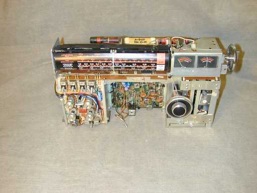
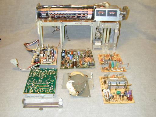
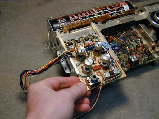
will also need to unplug the leads from the speaker. The next photos show front and back views of the chassis.

The R-7000's circuitry is divided into six main circuit boards:
-
LW/BC tuner
-
FM/AIR/VHF tuner
-
Shortwave
-
Controls
-
Interconnect
-
IF/Audio
As previously noted, there is also a tiny circuit board tucked into the cabinet back, containing a few
power-supply components.
The Interconnect circuit board forms the backbone of the radio. It is positioned horizontally along the top, stretching across the length
of the chassis. The other boards are positioned vertically and plug upward into the Interconnect board via many
small pins.
The modular design makes it very simple to replace a single board, if needed. In a factory service setting, a
technician could quickly substitute a new board for an old one, to instantly solve a problem.
Today's repairman
may have a more difficult time diagnosing problems, since the tightly-packed construction makes it impossible
to reach many parts of the circuit boards with test probes while the radio is assembled. If you remove a board,
then the radio can't be powered up unless you build a cable to connect that board to the Interconnect board.
Fortunately, I didn't need to build any custom cables. I did need to remove all of the boards, however, since
the filter capacitors I wanted to replace were located on the Interconnect board. And the Interconnect board can't
be loosened for service until all the others are pulled out.
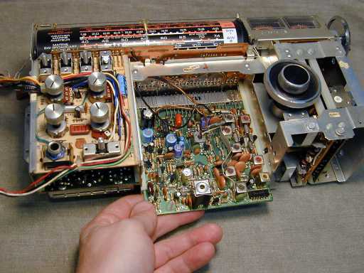
Let's pull some boards! Looking at the front of the chassis, the IF/audio board is the big green one in the middle.
It's held in place by a metal plate to its right, which is secured with screws. After removing the screws and the
plate, the IF/audio board slides out toward the bottom of the chassis.

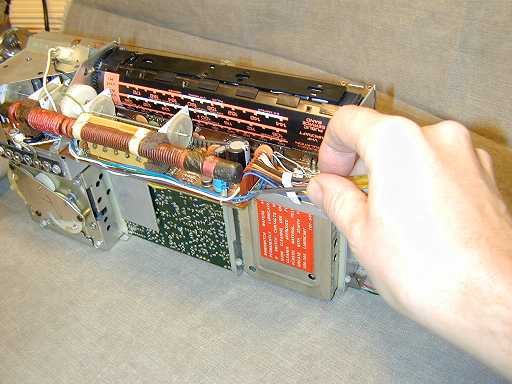
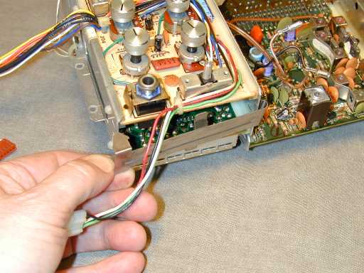
The Control board is the one with the small knobs
and switches. It connects to the Interconnect board in two ways: with built-in pins at the top of the board
and also with a cable that stretches around the chassis. I used a small screwdriver to loosen the cable connector,
then gently pulled it free with my fingers.

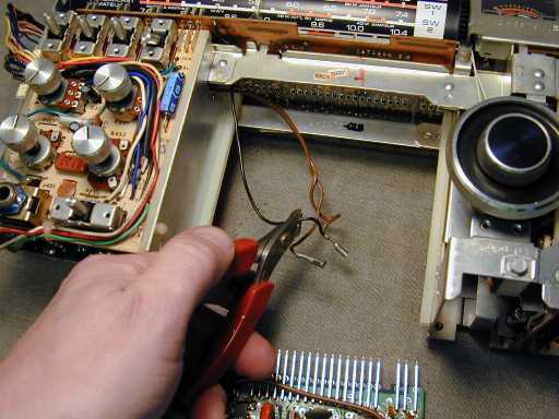
The cable was strapped to the chassis with a plastic tie, which I snipped.

Removing the Control board also requires snipping a wire leading to the speaker connections. Don't
forget to re-solder and insulate that connection when you reinstall the board.

The Control board is held in the chassis with a thin spring clip at the bottom. Remove the clip, and
the board slides out.


The Shortwave board slides out next.

Before removing the two tuner boards, turn the tuner all the way to one end of the dial (and make a note of
which end you chose!) Then avoid disturbing the tuning capacitors while the boards are out of the chassis.
This ensures that the tuning will be the same after reassembly.
Similarly, turn the bandswitch to either the last or the first frequency band.
This is necessary because you'll be loosening the bandswitch shaft and tuning dial later on.
If you omit this step, your dial may show the wrong band after you put everything back together.
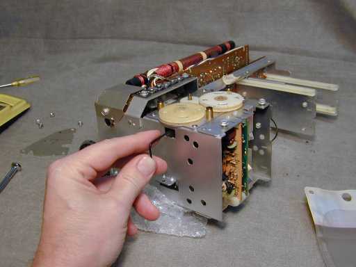
To begin removing the tuner boards, turn the chassis over and unscrew the tuning gear assembly. It is held
with screws in the corner of a mounting plate, as shown here. Remove the screws, but don't try to pull off
the assembly yet.

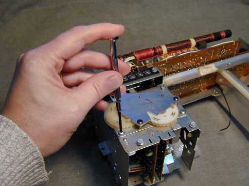
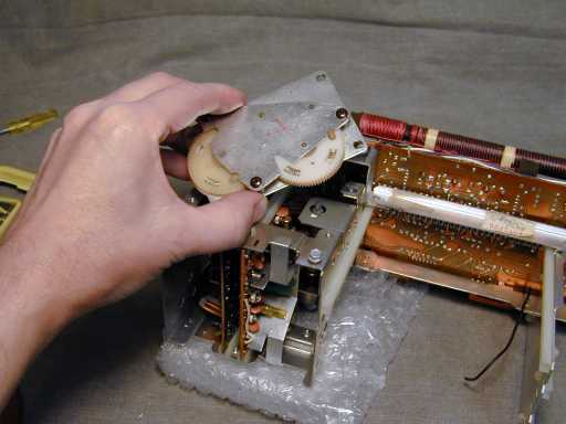
To release the tuner boards, you must free the shafts of the tuning capacitors from the gear assembly. A thin
Allen wrench is inserted through openings in the chassis to release setscrews holding the tuner shafts to gear
collars. A strong flashlight comes in handy during this procedure. (Note that you do not need to remove the top
plate from the gear assembly as shown here; I did that by mistake but quickly learned that it's not necessary.)


Now the tuner drive assembly can be lifted off.

Then you may slide out the tuner boards.

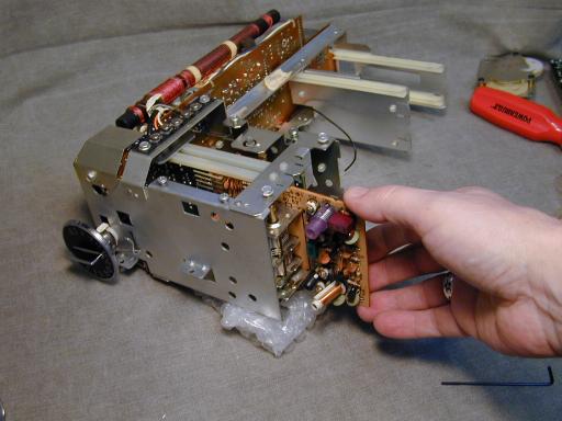
Phew! Here is the empty chassis with boards and tuner drive assembly laid out in front. Before going any farther,
set all the boards aside and make sure you can identify all of the parts and pieces for reassembly.
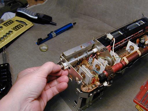
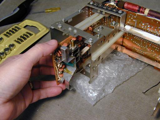
The Interconnect board is held to the chassis with several hex-head screws. Reaching all of them will
require removing the bandswitch knob and cylindrical tuner dial as well as a soldered-on corner plate.
In the next photo, I have removed the knob and am starting to remove the first mounting screw. Be
very careful during this phase to avoid damaging the fragile loopstick antennas.

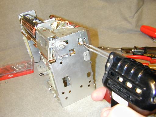
On my set, this corner plate of the chassis was secured with a single blob of solder. You may
need to use a soldering gun, rather than a small soldering iron, to heat this joint enough to free
it.
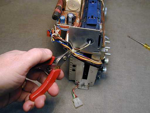
With the corner plate out of the way, you can get at this mounting screw. I didn't have a wrench that
fit in the cramped space, so I carefully loosened it with a crooked-nose pliers.

Next, you must remove the cylindrical tuning dial.
The first step is unscrew the mounting nuts on the bandswitch shaft and slide the shaft outward.
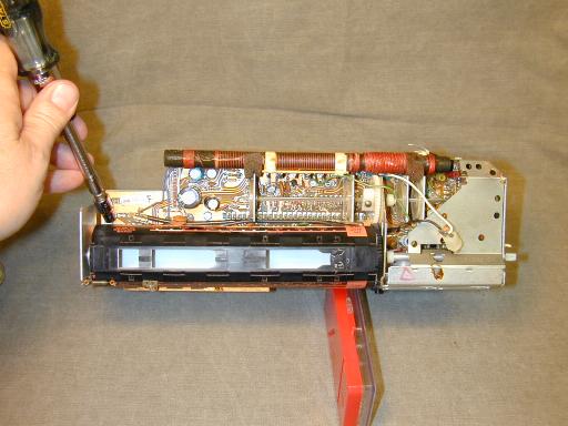
You'll also need to disconnect the pilot lamps from inside the dial. This can be done after
unclicking and sliding back a plastic cover on top of the dial. On my set, the plastic cover was
held with a dab of glue, which I carefully removed. In the next photo, you can see a pilot lamp
standing free on its mounting wire.
Replacement lamps may be tricky to find. A fellow collector sent me this information:
The correct dial lamp for this model is the G.E. #18, which is no longer made.
(Some new old stock may be found at electronic parts dealers.)

Eiko offers a #18 lamp that is electrically correct (14 volts, 0.04 amp). It
is, however, a bit larger in diameter than the G.E., so it is a very tight
fit (but it will go in). Removing one requires pushing it out from the bottom
of the socket with a small screwdriver or similar tool.
At this time (2015), you can get Eiko #18 lamps from
1000Bulbs.com.
If that source stops carrying them for some reason, they may be available elsewhere; do an Internet search for "Eiko 18 lamp."
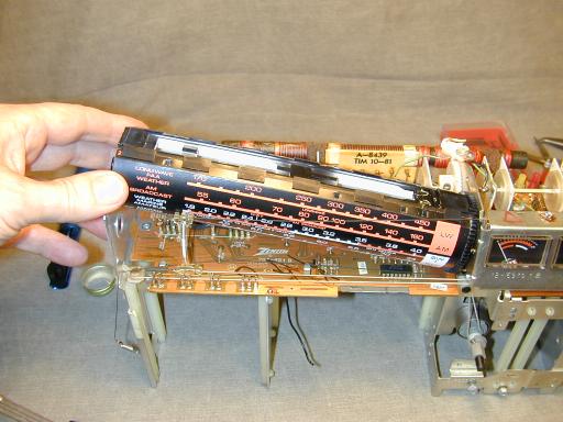
With the shaft pulled back, you can gently remove the tuning dial. Again, you should previously have
set the bandswitch to a known position, so you can leave everything set up to switch correctly after
reassembly. Set the tuning dial aside and don't mess with it until you're done.
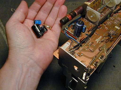
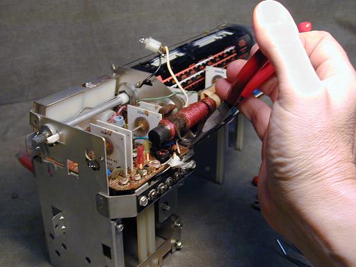
At long last, I was able to gently wiggle the Interconnect board upward far enough to replace
the filter capacitors. In this photo, the old capacitors are in my hand and the new ones are installed
in the board.
Finishing Up
To reassemble, as the old repair manuals say, simply reverse the previous procedure. As usual, it
took far less time to put things back together than it did to puzzle out the disassembly process.
When I got everything buttoned up, I was dismayed to find that the radio worked no better than before.
Back to the drawing board!
This time, I began debugging the power supply problem at the power cord, and worked my way forward,
using a multimeter to test for voltages and continuity every step of the way. I found two problems.
There was an intermittent
connection at the little circuit board carried in the back cover. The main power switch was also
flaky, sometimes making a good connection, and other times not. A dab of solder fixed the intermittent
connection, and a thorough treatment with DeOxit spray cleaner fixed the power switch.
Now my TransOceanic worked like a charm! In hindsight, I could have saved a lot of time by
taking this methodical approach to troubleshooting, rather than assuming that the power-supply
electrolytics were at fault. Oh well—at least I can plan to use this radio for a long time
before the new filters need replacing!
In the meantime, I have spent many a happy hour listening to my R-7000-2. It's an outstanding
portable multi-band receiver, which represents the end of a historic and interesting phase
in radio development.
Visitors to this website often ask questions about value. For what it's worth, I paid $50 for
this radio and considered it a good deal. The TransOceanic book by Bryant & Cones gives an
average value of $220 for the R-7000 series. As mentioned earlier, I would pay more for the
R-7000-2 than for earlier models because of its more robust tuning mechanism.
|