Gibson Clavioline Keyboard Instrument (1953)


The Clavioline is an early electronic
keyboard instrument, similar to my Hammond Solovox.
Both of them are monophonic (single voiced) and tube powered, consisting of a keyboard
and an amplifier.
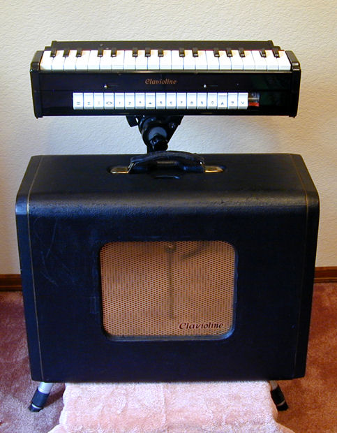
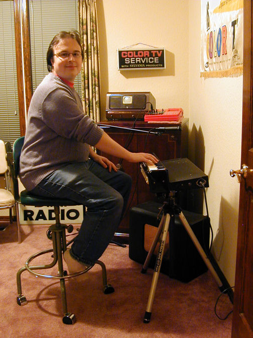
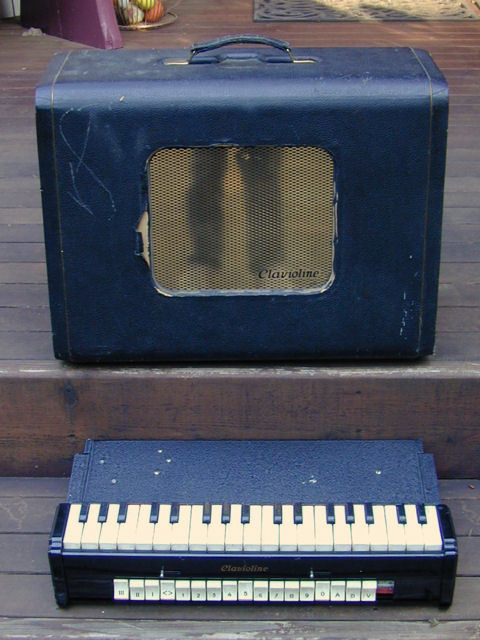
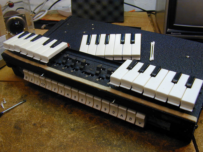
The first photo shows my Clavioline after restoration. In the second photo,
my son, Peter, is seated at the keyboard. Click the musical icon to hear him playing a brief
theme from the well known 1962 song, Telstar.

Description
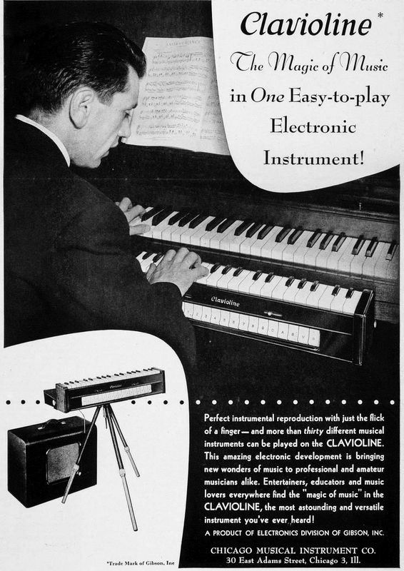
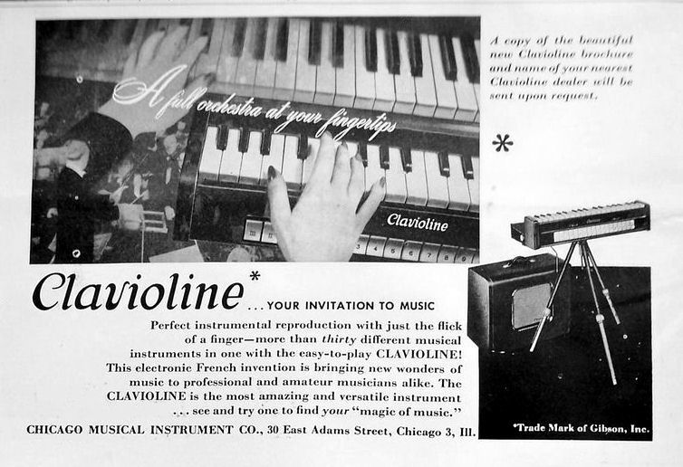
My Clavioline is a Gibson, shown here in some mid-1950s ads.

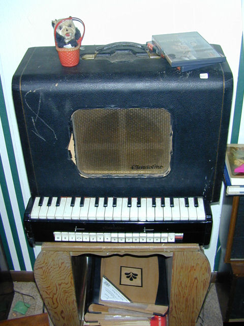
As illustrated, a Clavioline can be used in two ways. First, like
a Hammond Solovox, it can be mounted on a piano and played as an adjunct
to the piano keyboard. Or, mounted on a tripod, it can be played as a standalone
instrument.
Either way, the artist must be sitting, in order to operate the knee-lever
volume control, or "expression" control, as termed in Clavioline literature.
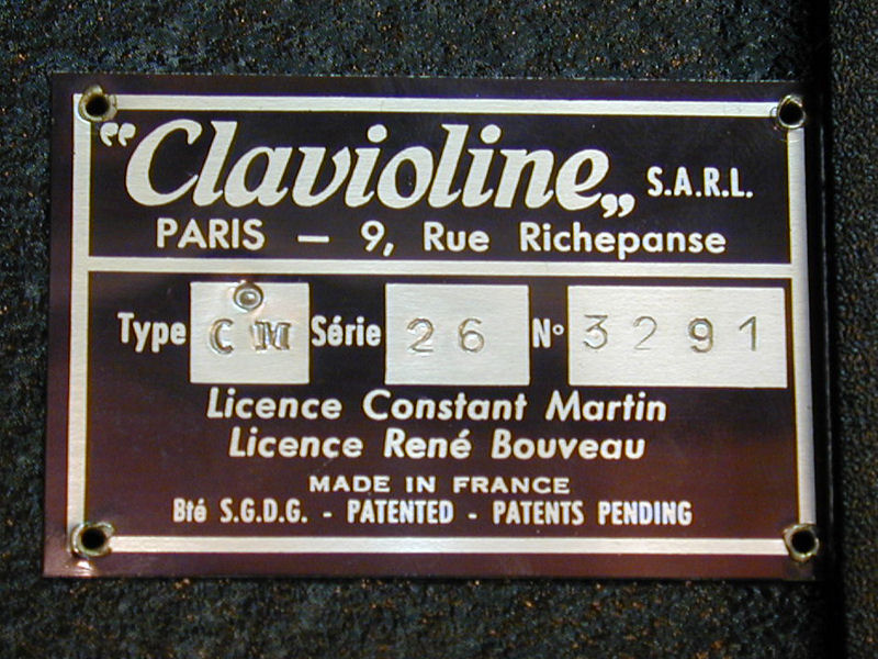
Every Clavioline was created under license from the inventor,
Constant Martin, as seen on my keyboard's ID plate:
In the United States, Claviolines were manufactured by the Gibson instrument
company. They were also built by
Jörgensen
in Germany and
Selmer in England.
Since the Jörgensen and Selmer instruments differ in construction as well as
features, I'll refer you to the previous links for details about them.
Martin applied for a U.S. patent in 1948 and on August 7, 1951, he was granted
patent 2,563,477, "Electronic Musical Instrument."
Click the thumbnail to read the patent, with the full description and
original drawings:

If you're looking for a layman's explanation of how a Clavioline works,
the patent is not the place to start. Like most patents, it is written
in a dense polyglot of legalese and techno-jargon, aimed at establishing
precedence and forestalling infringement. Furthermore, since a patent is
drafted to protect ideas and principles in the broadest possible fashion,
this one doesn't literally describe the Clavioline as it was commercially
realized. Still, it's interesting to see a contemporary
expression of Martin's idea.
Interestingly, the last page of Martin's patent description references an earlier (1939)
patent, number
2233258, "Electrical
Musical Instrument."
Held by Laurens Hammond and John Hanert, that is
the seminal patent for the Hammond Solovox. Some long winter's evening, I'll
need to sit down and compare the circuitry of these two
similar instruments and decide how different they really are. The
Clavioline has more voices and a larger octave range, but presumably
more than that was needed to establish that it wasn't merely a rehash
of the earlier Solovox design.
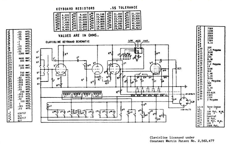
The only Gibson service data that I have found so far are these two schematic diagrams for the
power/amplifier chassis and keyboard chassis:

Apologies for the low quality of these schematics. If you have a more detailed Gibson service
manual, or even clearer copies of these schematics, please
contact me.
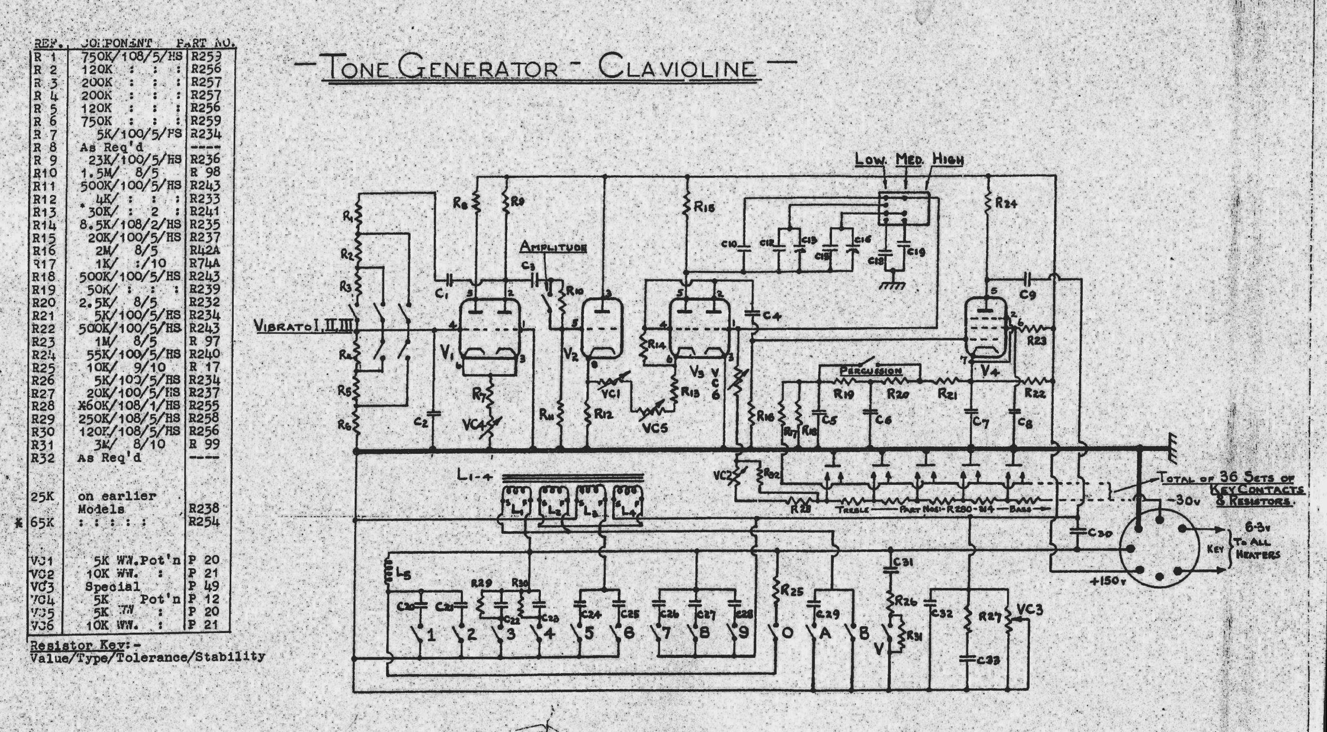
I also have obtained some Selmer documentation, which is not terribly
useful, owing to differences between the American and English instruments. This
page from the back of one manual is not identical to the Gibson keyboard
schematic, but perhaps it will help you identify a few more items in the
blurry Gibson scan:
Finding a Clavioline
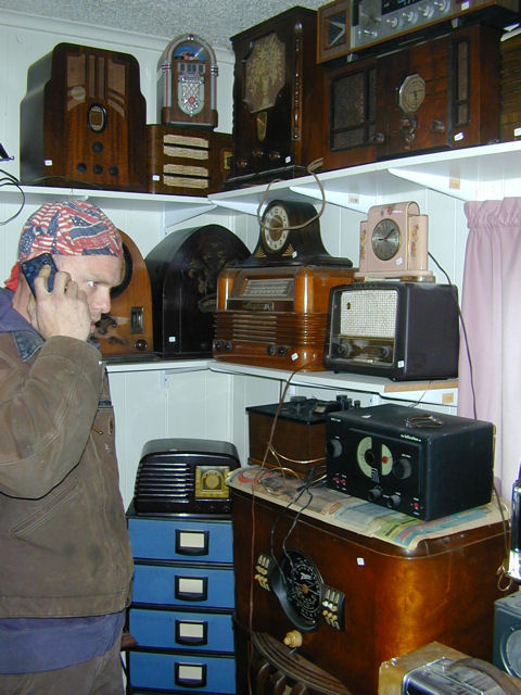
I found this Clavioline at a crowded estate sale in 2011. The sale was located in a tiny
house, whose every room was crammed to the ceiling with shelves for antique
radios and other electronics. The
fellow in this photo was on the phone, describing every radio in the house
to someone on the other end.
I didn't see any radios or TVs that I wanted, but this little keyboard
caught my eye. I recognized the name Clavioline as a monophonic
instrument like my Solovox.
The price ($250) was too high to tempt me, but I returned the next day and
made a deal for half that price. Here is my Clavioline after unloading
back at home.
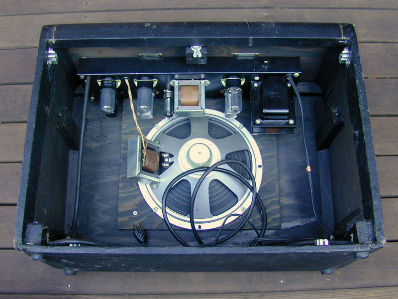
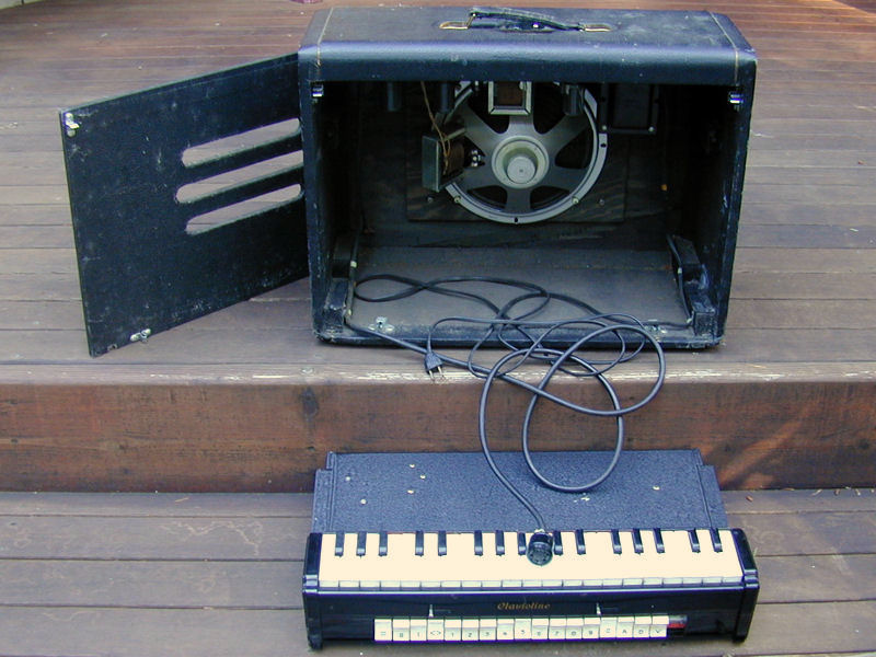
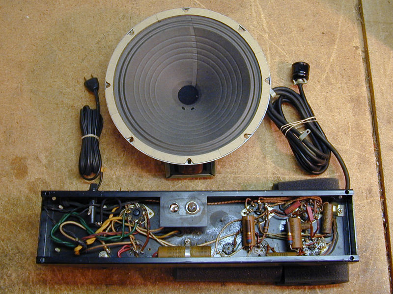
Removing the back cover reveals the speaker, power cord, connecting cable,
and the power/amplifier chassis. To transport the Clavioline, you stow the
keyboard unit in the back of the cabinet and pop the cover back on.

My Clavioline has no identifying information other than the ID plate
shown earlier, which says Made in France. After a little research, I
concluded that it's a Gibson model, sold under license in the United States.
Since its components (capacitors and whatnot) are also of U.S.
manufacture, I presume the whole thing was manufactured here,
not imported as the ID plate suggests.
Some time later, I saw photos of an identical model with a sticker
on the back of the speaker that said Gibson Ultrasonic. Perhaps mine
once had the same sticker, but it fell off and became lost.
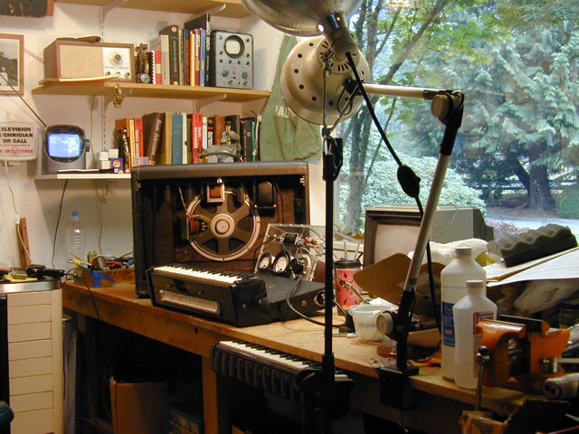
First Power-Up
Moving my Clavioline to the workshop, I cautiously powered it up, using my
variac and watching its ammeter for excessive current draw.
The Clavioline worked . . . sort of. I could hear notes from many of its keys,
but they were sometimes intermittent. A few of the tone switches had an effect,
but others seemed to do nothing, and the vibrato switches were also inoperative.
Not to worry, every 60-year old tube device needs service, chiefly in the
form of new capacitors. It's not surprising that the keyswitches and
controls need cleaning, too.
Electronic Restoration
We'll examine the two Clavioline chassis separately, starting with
the keyboard unit.
A Clavioline is not especially complex, compared to other tube
electronics. A full restoration will take a number of hours, however,
so don't expect to give yours a complete overhaul in an evening.
Keyboard Unit Disassembly
By removing a few screws, you can take off the large cover plate on the
bottom of the keyboard unit. This exposes the tubes, potentiometers, and
other electronic components.
After removing those screws, I put them back into the holes they came from. This
is a great way to avoid losing parts!
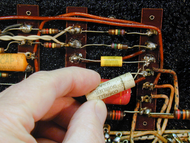
The pink tubular components are "Tiny Chief" brand plastic-coated paper capacitors.
This type of capacitor is notoriously unreliable and should always be replaced,
as explained in my recapping article.
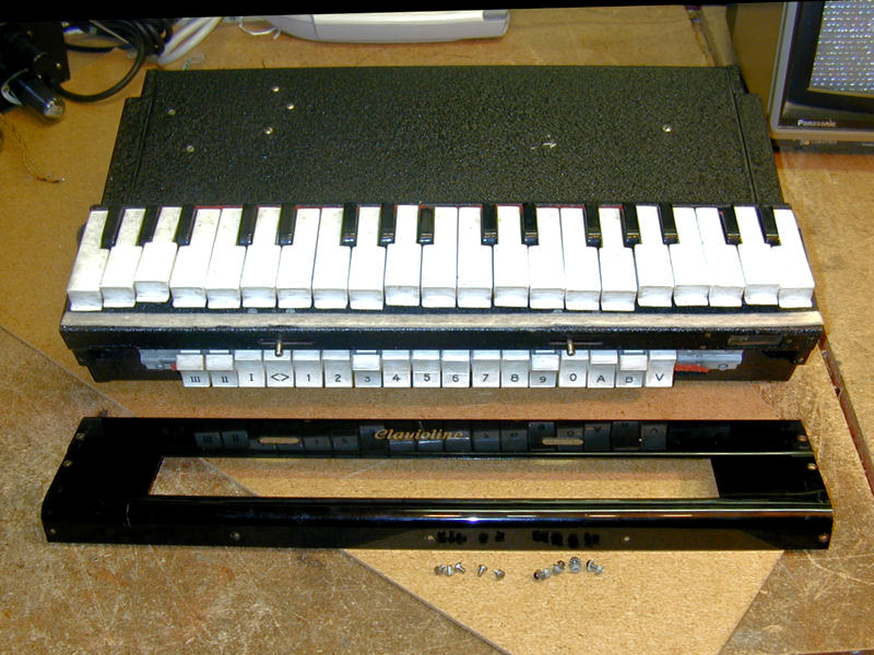
The front panel of the keyboard unit is secured by ten screws:
When you remove the front panel, all of the white keys will rise up
a little on their springs, although they are still held on by screws from
the back.
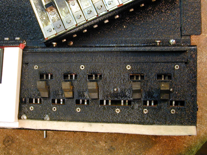
Removing the panel exposes the rocker-style control switches, which select
tone combinations and vibrato effects. When a switch is toggled,
its blade-shaped upper contact completes a circuit with two or three springy
contacts below. As the photo shows, some of those contacts are dark with dirt and oxidation.

The control switches have either two or three springy contacts and the
circuit is completed when the blade touches them,
thus activating the tone filter or other components wired to the contacts.
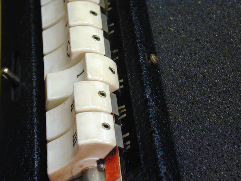
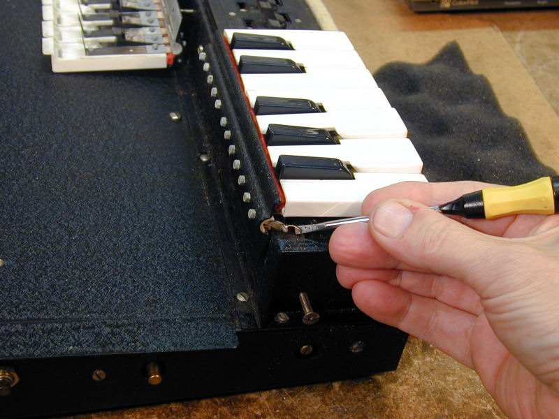
Cleaning the Control Switches
I'll clean the control contacts with Q-tips dipped in DeOxit D100L electronic cleaner.
Don't press too hard on the contacts, lest you deform them. After wetting the Q-tip with DeOxit, I gently twirled it on each contact until the discoloration went away.
You also need to clean the edge of each blade, of course.
Here are three switches after some cleaning.
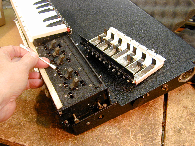
Cleaning the Keyswitches
The keyswitches are similarly constructed, but they are momentary-contact switches,
completing the circuit only while you hold the key down. To clean them, you'll need
to remove the switches, which come out in three banks, screwed on from behind.
The frame has two rows of slots that expose the springy contacts for the keyswitches.
The five rubber bumpers protruding from the frame are in line with the black keys.
When you release a black key, a small lip on its end hits the lip on the bumper and thus prevents
the key from rising up too far. (The front edges of the white keys are similarly
held when at rest, by the edge of the keyboard front panel that we removed earlier.)


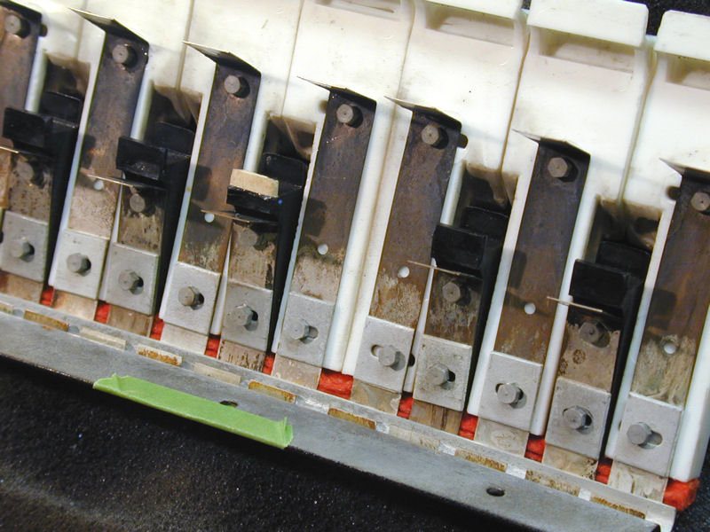
Each keyswitch has two springy contacts below, and every keyswitch blade is
connected to chassis ground. Depressing the key grounds both contacts, with
a very slight delay between touching the first and second contact. This
ensures a clean attack for the note, without any electrical pops or clicks.
As with the control switch contacts, I dipped a Q-tip in DeOxit and twirled
it on each set of contacts to clean them. After finishing the first bank,
I reinstalled it and proceeded to the second bank.

The lip on one of the black keyswitches had broken and become lost. I cut
a little piece from a popsicle stick and glued it on with epoxy. Not
as beautiful as an original key, but now it works exactly the same!

The next photo shows an important detail.
Before removing the third bank of keys, you must unsolder this wire, which
connects every keyswitch to chassis ground. Solder this wire back in place
when you reinstall the bank; a secure ground connection is critical for
keyboard operation.

Eventually, all of the keyswitches were clean and back in place.
Replacing Capacitors and Resistors
Recapping is a routine practice for every
tube device from this era. Since this Clavioline article is likely
to be read by non-radio folks, I'll describe the basic process in
more detail than usual.
How to Replace a Capacitor
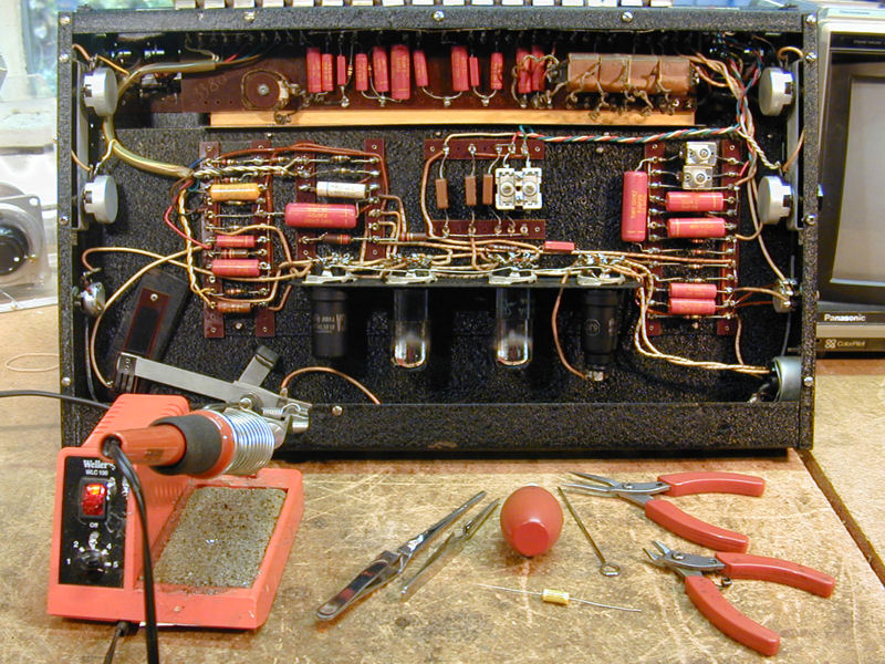
This photo shows the keyboard chassis and
the tools that I'll use: a soldering
iron, wire cutter, needlenose pliers, bulb solder sucker, and
a couple of steel tweezers.

The Clavioline chassis is easy to work on, compared to most radios and TVs
of the era. Components are neatly arranged on phenolic terminal boards and
their connections are readily accessible, rather than buried under
other components and wires.
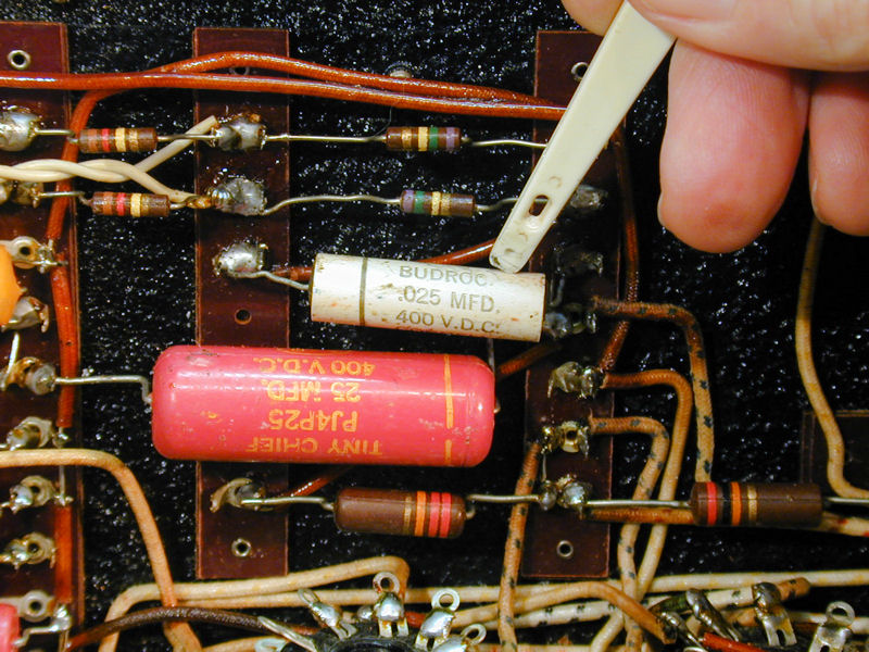
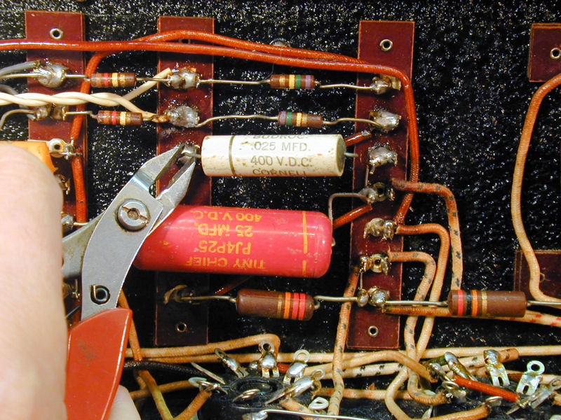
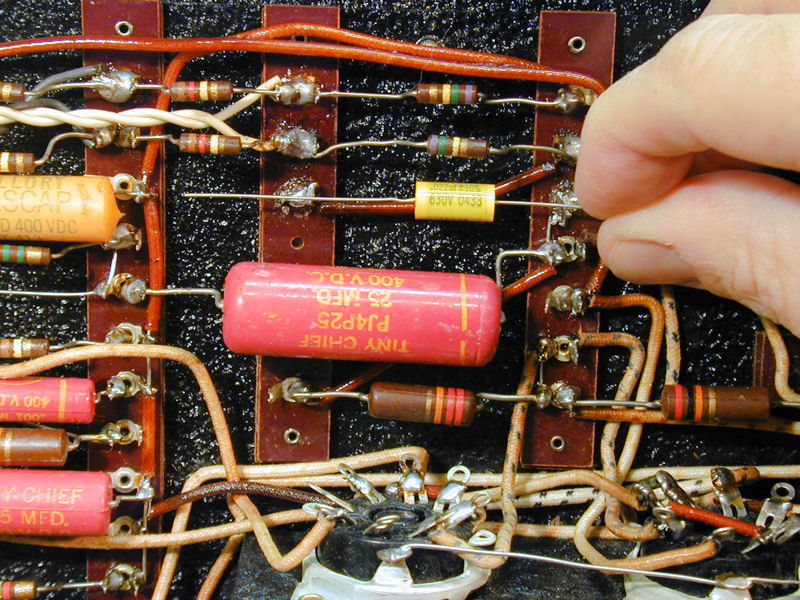
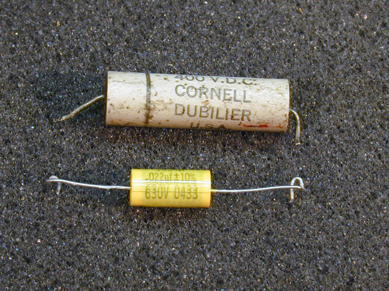
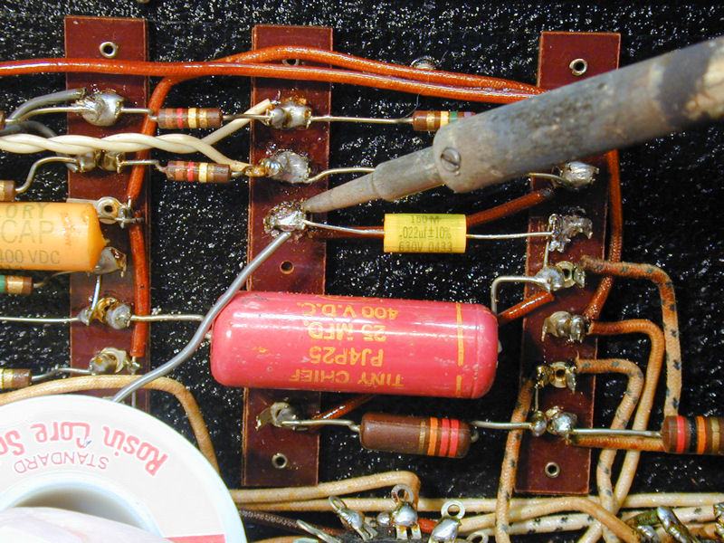
We'll begin by replacing the capacitor shown in the next photo. It's likely
a replacement, installed during past service. These white
tubular caps were no better than the pink Tiny Chiefs, so I'll
replace it even though it may be a few years newer.

The old capacitor's value is .025 mfd. The schematic calls for .020 mfd. I'll replace it
with the modern value, .022 mfd. A difference of .002 from the specified value will
not matter. Most old components were manufactured within a tolerance of
20% above or below the nominal value, so a difference of .002, or 2%, is well
within the needed value range.
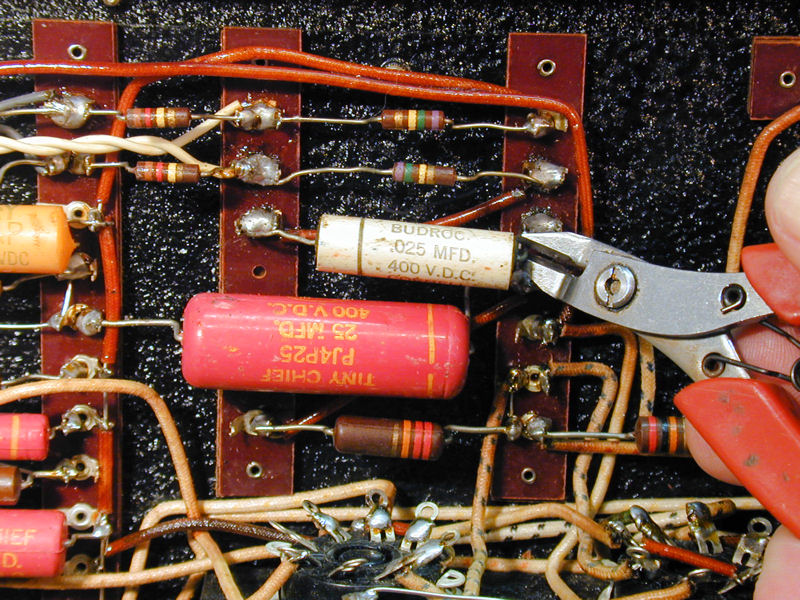
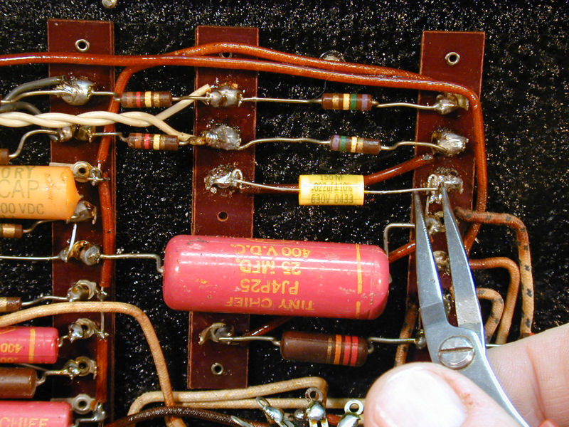
I carefully note where the capacitor is connected and then snip each end.
Then I can melt the solder on each terminal and remove the wire stubs with
a plier. This is easier than trying to work the wire loose from the
terminal while the capacitor is still connected, which can damage the
terminal if you yank too hard.


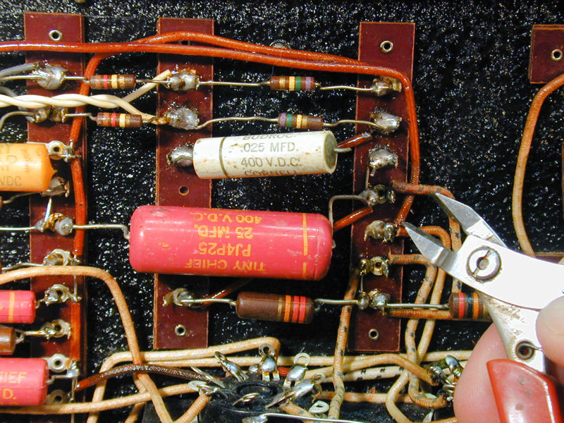
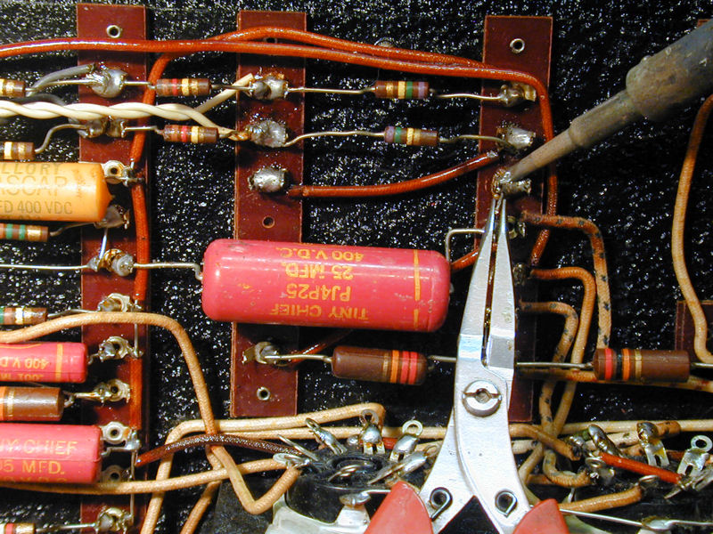
After I remove the first wire stub, I reheat the joint and remove
excess solder with the solder sucker. I repeat the process on the second terminal.


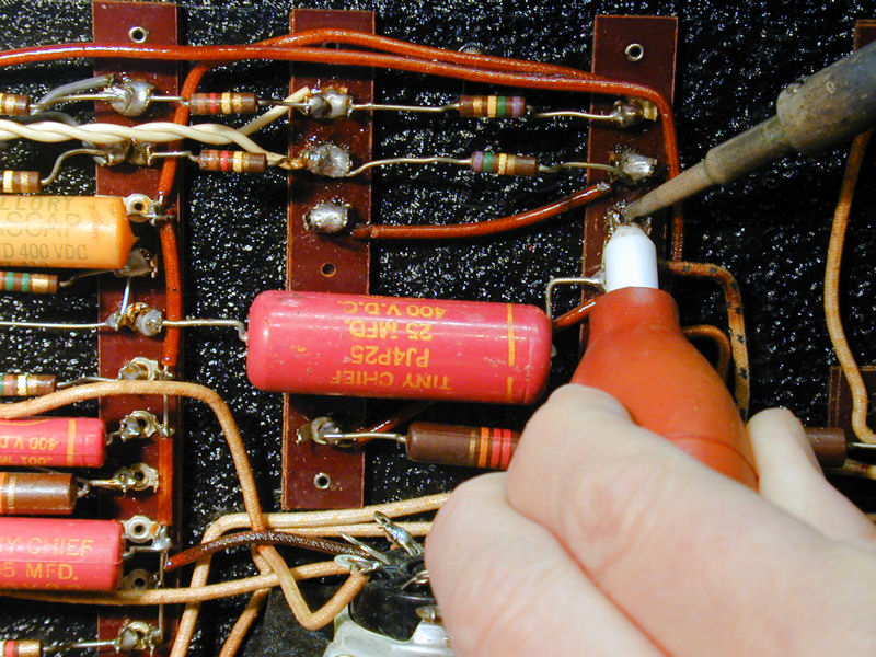
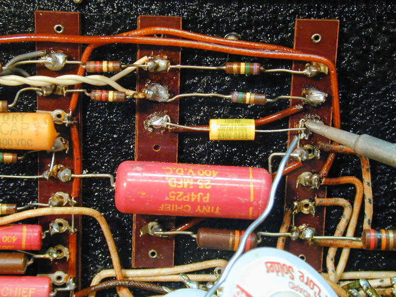
The new capacitor is smaller than the original and it will easily fit the space.
I snip its ends and bend them to fit neatly around the terminals. If a terminal
has holes (these don't), you can run the new capacitor's lead through the
hole and bend it around the terminal a bit, before snipping to length and crimping.


Next, I crimp the pre-formed wire ends onto the terminals and secure them with new
solder. Always heat the joint first and then apply the solder to the heated
joint rather than to the hot iron. This distributes melted solder evenly
throughout the joint. It is very bad practice to melt solder on the iron
and let that drip onto a cold joint.


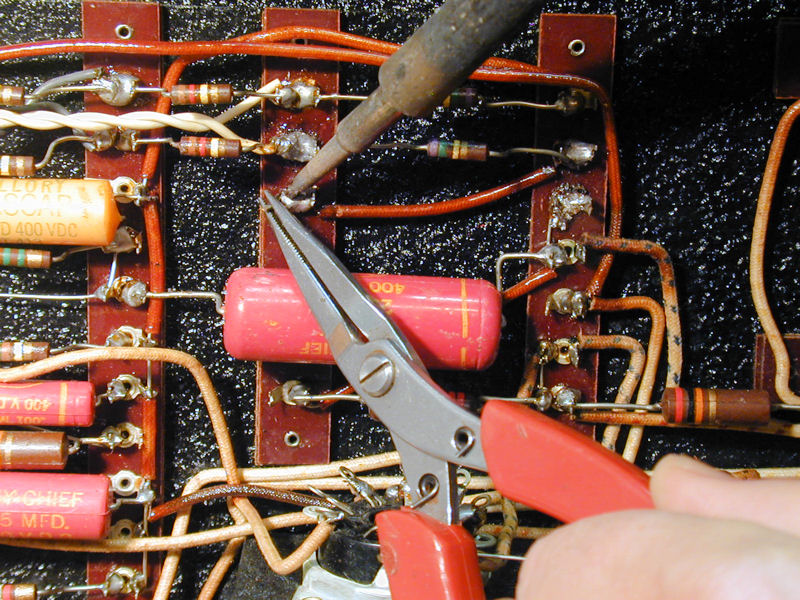
Sometimes, when a delicate component is connected to a terminal, I'll temporarily
clip a metal tweezer onto that component's lead, to act as a heat sink and
prevent overheating damage. That's not necessary in this case, since I'm working
quickly and heating the joint only long enough to flow the solder into
and around the joint.
We have replaced one capacitor. Only a few dozen more components to go!
Replacing the remaining capacitors was simply more of the same.
The process looks laborious when you document every step, but with practice,
you'll be able to replace a capacitor in only a minute or two.
Replacing Resistors
In a typical radio or TV restoration, I leave all or most of the original resistors
in place. Resistors are more reliable than capacitors and in many cases their
precise value isn't critical in the first place.
Unless otherwise specified, resistors in old tube devices are expected to be
within 20% of their nominal value, and in many cases a radio or TV will work
normally even if a resistor's value has drifted beyond that range.
The Clavioline is a musical instrument, however, with circuits intended to
oscillate at particular frequencies. The resistors in its
keyboard chain are of extremely high precision and stability, and they have unusual values
relating to musical frequencies, such as 6300 ohms, 6670 ohms, 7074 ohms, and so on.
The high-precision keyboard chain resistors seem to be fine—each key
is in tune relative to the others—and so I won't touch them. Most of the other resistors
are of the everyday carbon variety, however. I'll replace those as long as I have
the chassis on the workbench.
Replacing resistors on the terminal boards is the same as replacing capacitors
there. Remove the old resistor and solder in the new one.
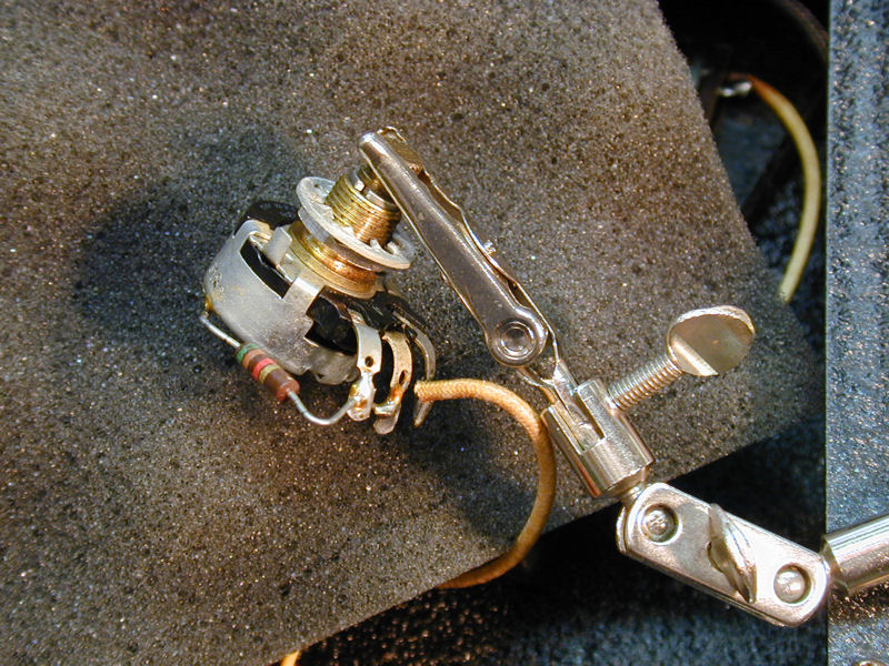
Here's a resistor mounted in a different spot, on potentiometer VC1, which
controls the vibrato. The resistor's value is 5.1K ohms, indicated by the
green-brown-red color bands:

Replacing this resistor is easier if you first unscrew the potentiometer from
the keyboard frame, as shown in the previous photo.
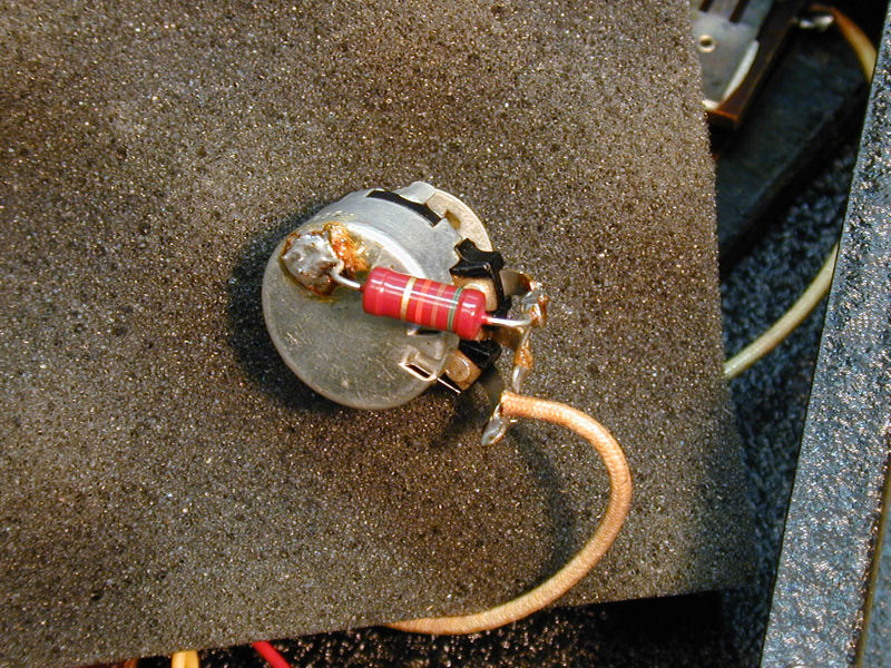
One end of the resistor connects to a terminal on the potentiometer. The other
end is soldered to the potentiometer's metal case, which connects to the
keyboard unit's grounded chassis through its screw mount. Here is the
new resistor in place:

Cleaning Potentiometers
While I have the potentiometer out, it's a good time to clean its interior
using DeOxit or a similar electronic cleaner. In the previous photo, notice the little opening
in the potentiometer case near the terminals. Spritz a tiny amount of cleaner into that
opening and then turn the potentiometer all the way back and forth a number
of times, to distribute the cleaner. Dab up any excess cleaner that drips
out of the case and let the Clavioline sit overnight before you apply
power again, to make sure the cleaner has evaporated completely.
I cleaned the other carbon type potentiometers in the same way. The
larger potentiometers (without openings in the case) are the wire-wound
type, which normally requires no cleaning.
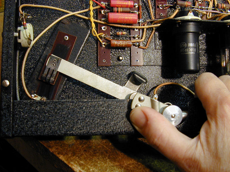
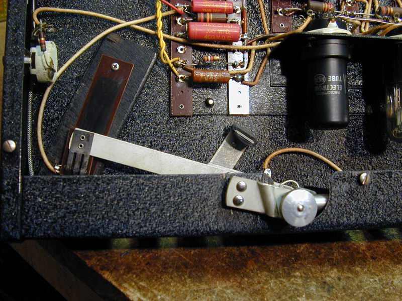
The knee-operated volume control has a different type of potentiometer.
The rotary type shown earlier has a metal wiper inside, which moves in an arc
around a resistive carbon track, producing lower or higher resistance as
you turn its shaft. The potentiometer shown next also uses a metal wiper on a resistive
carbon track. However, the track is a rectangle on a flat phenolic board
and the wiper moves back and forth in a straight line (actually, a very
shallow arc) on the board.
These photos show the volume control in operation:

Here's a little
animated GIF that show the control's operation more clearly.
My volume control worked perfectly without cleaning, so I left it alone.
If you wanted to clean it for some reason, I would be careful not to rub
the resistive track too hard, lest you wear it off and ruin the potentiometer.
When the Clavioline is reassembled, a long, L-shaped lever is mounted
on this volume control, so that you can move it with your knee.
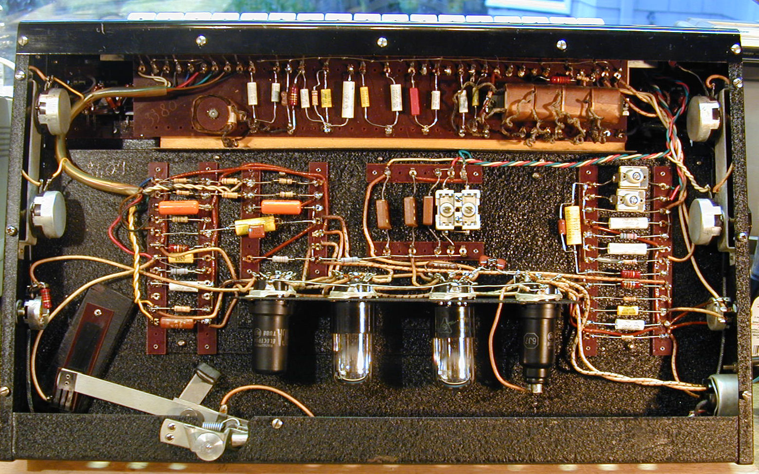
Clavioline Keyboard Chassis Restored
This photo shows the fully restored Clavioline keyboard chassis from
underneath:
All told, I replaced about 50 capacitors and resistors in this chassis, in addition
to cleaning the keyswitches, control switches, and potentiometers.
Power/Amplifier Chassis Restoration
The second Clavioline chassis contains circuits for the power supply and
audio amplifier.


This chassis is far simpler than the keyboard chassis and its restoration
was straightforward. Again, in the interests of reliability and longevity,
I replaced its resistors as well as the electrolytic and paper capacitors.
Two of the electrolytics are multi-section cans mounted upright on the
chassis. I left the cans in place above the chassis, but disconnected their
contents and wired new capacitors underneath. You can read about several
alternative methods for
replacing electrolytic cans in my
recapping article.
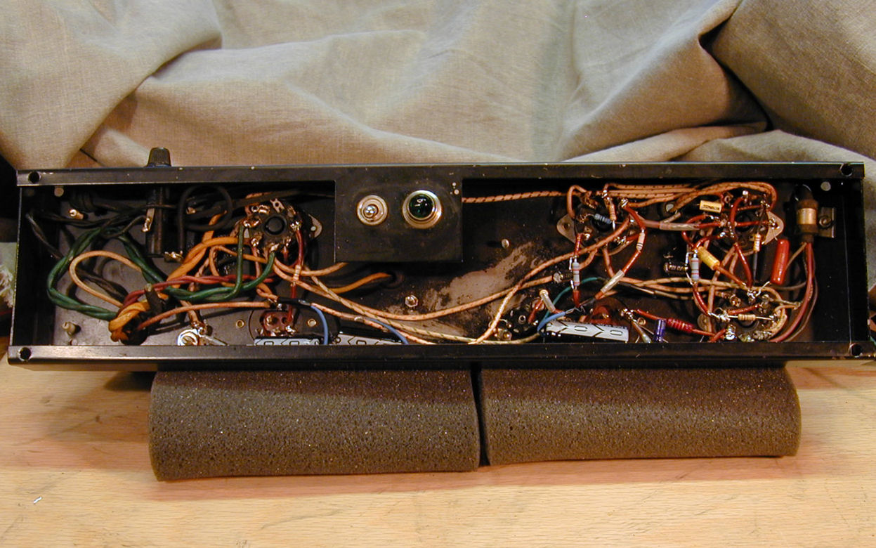
This photo shows the power/amplifier chassis after restoration:

As you may recall from earlier photos, this chassis mounts upside down
inside the speaker cabinet. Its power switch and green pilot light
protrude through an opening below the cabinet's handle.
Cabinet Restoration
The Clavioline cabinet is covered with leatherette, a vinyl-coated fabric.
When I first got my Clavioline, it had a tear in the front near the speaker
grille, and assorted scuffs and scratches.
The first step was to clean the covering with Windex and reglue the flaps of
turn fabric. Next, I used black liquid shoe dye to conceal the scratches and
give the covering a uniform color. In the following photo, I have begun
by coloring the strips along the sides.

Notice the narrow band of exposed plywood around the speaker opening. Perhaps
this was originally covered with a thin strip of leatherette, which fell off.
I don't have leatherette on hand, but at least I can color the bare wood black
so that it doesn't attract attention.
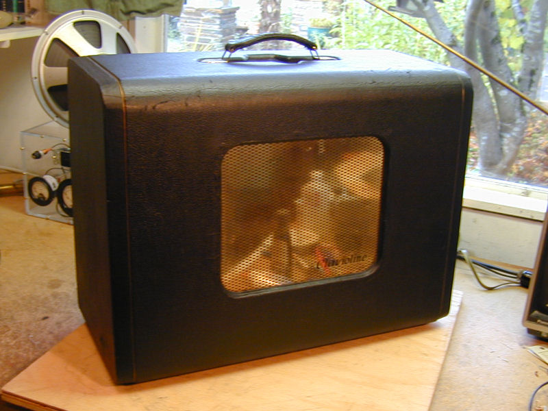
After coloring the whole cabinet, it looks much better.

You can still see some marks of age, but I wouldn't be embarrassed to bring
the instrument onstage.
Final Thoughts
Here is my Clavioline after restoration:
For this photo, I mounted the Clavioline on an old, heavy-duty camera tripod.
I assume that the original tripods were similar, based on pictures in
the magazine ads, perhaps with a wider bracket at the top to steady the
heavy keyboard against pushing on its ends.
Of course, in a performance setting the speaker would be aimed outward
at the audience, not perched in front of the keyboard as in this photo.
The connecting cable is long enough to place the speaker alongside
the keyboard.
I haven't yet had time to try out all of the Clavioline's different voice
settings, much less compare its performance to my Solovox. Perhaps when my
son comes home for the holidays, we can set up both instruments side by
side for comparison, and even record a couple of audio clips to add
to this article.
I'm seeking a few minor items. My Clavioline is missing the rightmost control
key, labeled P. If you have any spare key for sale, I'd be interested in that.
A working key with a different label would be better than no key at all.
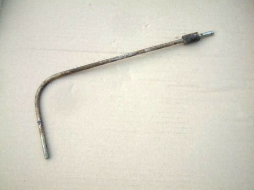
I'm also missing the knee lever for the volume control. I can
use a makeshift piece of bent metal in the meantime, but it would be nice
to have the original article. The following photo shows the knee lever from
a Selmer Clavioline, which is similar but not identical to the Gibson lever:

Lastly, as noted earlier, I'd like to find a complete Gibson service manual,
as well as an owner's manual. If you have any or all of these items,
kindly contact me.
|


