|

Replacing Capacitors in Old Radios and TVs
Why Replace Capacitors?
Second only to power cords, capacitors are the most failure-prone components in old radios
and televisions.
In a professional overhaul, it is common to replace all of a set's large electrolytic capacitors
and small paper capacitors. This article explains how to do that.
Often, this "recapping" is all that the radio or TV needs to be restored to health.
Incidentally, tubes are much more reliable than capacitors. Many tubes will last for decades.
Professional restorers replace a tube only if it is defective. "Retubing" a radio—replacing
all its tubes for no particular reason—is a waste of money and does not improve performance.
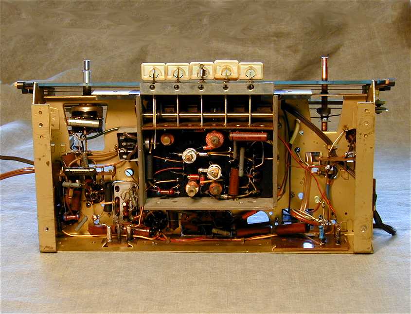
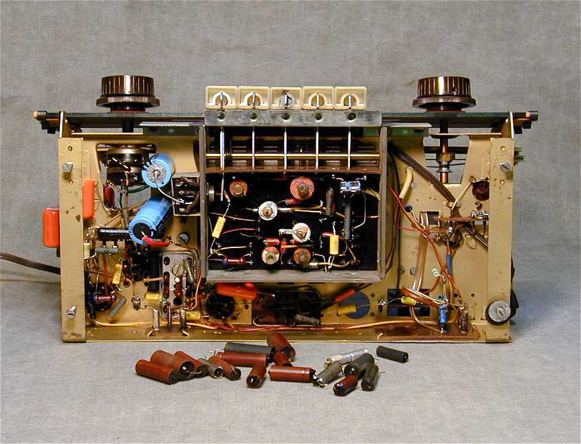
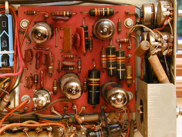
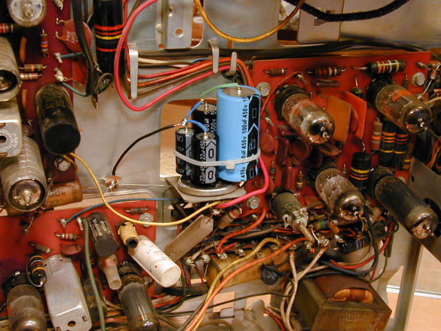
These photos show the underside of a Grundig 940W radio
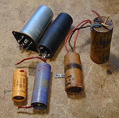
before and after recapping. The second photo shows the capacitors that were
replaced. This is a multi-band radio with FM and two AM bands. A simpler radio
will have fewer capacitors, often under ten.


The new capacitors in the second photo are colored yellow, orange, and blue.
Types of Capacitors
Before getting to work, let's make sure you know what to replace.
Some kinds of capacitors—paper, molded paper, and electrolytics—are failure-prone and
need to be replaced. Other kinds, such as mica and ceramic, rarely need replacement.
To avoid wasting time and money, you must be able to tell them apart.
Electrolytic capacitors are polarized, meaning that they have positive (+) and
negative (-) leads.

|
Electrolytics are the largest capacitors in the radio, with values from about
5 mfd (microfarads) to as much as 80 or even 200 mfd. Common values are 20 mfd and 40 mfd.
Electrolytic capacitors are very failure-prone and are usually replaced.
|
Non-electrolytic capacitors are not polarized. Neither end is positive
or negative. They have smaller capacitance values than electrolytics,
anywhere from .0001 mfd to .5 mfd. Common values are .01 mfd, .02 mfd, and .05 mfd.
Below are the common types of non-electrolytic capacitors.

|
Paper. Very unreliable, should always be replaced. Even if working now, they may soon fail!
|

|
Molded paper (round). Very unreliable, should always be replaced. These are simply paper capacitors
in plastic shells. The black ones are sometimes called Black Beauties or
"bumblebees."
|

|
Molded paper (flat). Very unreliable, should always be replaced. These are also paper capacitors
in plastic shells. Usually coded with colored dots.
|

|
Ceramic. Round and flat. Extremely reliable. Do not replace without specific reason.
|

|
Mica. Squarish and flat, thicker than ceramic, usually with color-coded dots. Reliable. Do not replace without specific reason.
|
Note that two of these types—mica capacitors and flat molded paper
capacitors—look similar. Both are flat, often with color coding
dots to indicate the value. It is easy to tell them apart by checking
the value. Mica capacitors have very small values, typically under
.001 mfd. The values of molded paper capacitors will be larger, similar to
other paper capacitors, such as .01 or .02 mfd.
Understanding Farads, Microfarads, Picofarads
Capacitance values are expressed in units called farads, named after the British physicist
Michael Faraday.
The capacitors found in radios and TVs have values in tiny fractions of a farad.
A microfarad is one millionth of a farad, abbreviated as mfd, mf, µf, or uf.
A picofarad is one trillionth of a farad, abbreviated as pfd, pf, or µµf.
This website generally uses the abbreviation mfd for microfarads and
pf for picofarads.
In vintage radios and TVs, capacitors typically have values in these ranges:
- Electrolytic: 1-200 mfd
- Paper: .001-1 mfd
- Ceramic and Mica: less than .001 mfd
Since a picofard is one trillionth of a farad, to convert
from microfarads (mfd) to picofarads (pf), you move the decimal point six
places to the right. For example:
.47 mfd = 470,000 pf
If you don't like doing such conversions in your head, you can look up the
values in this handy chart
from Justradios.com.
Checking Capacitors
You can't tell anything useful about a capacitor from its external appearance
unless it has exploded or is physically broken.
A paper capacitor may look gooey or melted, yet test OK. Conversely, it may look perfect, but test bad on
a capacitor checker. The leakage is internal, caused by water vapor that invisibly penetrates the
wax or plastic coating over time, no matter what the exterior looks like. Melted wax is often
the result of decades of normal operating temperatures inside the radio.
Electrolytic capacitors tell even less by their appearance. In extreme cases,
the case may bulge or even blow its end out. Much more often, a failed
one looks like new. Over the decades, the paste electrolyte inside
the cap dries out and becomes useless—a condition that you can't
detect with the naked eye unless you tear apart the capacitor.
Some people try to check capacitors for short circuits using an ohmmeter, but this test is
not very useful, since the majority of bad capacitors fail in other ways.
The most common defect in old capacitors is leakiness. An ohmmeter can't test for leaking
because the voltage that it applies is too weak. A capacitor might look OK
when testing with an ohmmeter, yet leak like crazy when enough voltage is applied.
The same is true of modern multimeters with a capacitor test function; that function
can tell you the capacitance value of a modern, low-voltage capacitor, but it's useless
for checking vintage capacitors.
To test old capacitors for leakiness, you need a capacitor checker that applies the
correct operating voltage, often over 100 volts.
Old capacitor checkers are available cheaply at swap meets and on eBay. Like all vintage equipment,
they will need routine service—including capacitor replacement—before they
are reliable and accurate. I own a couple of old capacitor checkers, made by Solar and EICO:


Disconnect one of the capacitor's leads before checking it. If it is an electrolytic, wax paper, or
molded paper capacitor, I usually just replace it, which takes less time than disconnecting,
testing, and (possibly) reconnecting. The test results for those capacitors are a foregone
conclusion. If the capacitor isn't already bad, it will soon become so!
Follow the Schematic!
It's essential to replace old capacitors with new ones of the same capacity and voltage rating.
I strongly recommend that you get a copy of your radio's schematic diagram.
The schematic will show the location and value of every part in the radio,
including capacitors. It often provides other information such as
alignment instructions or stringing diagrams for broken dial cords.
Many US radio schematics can be downloaded at no charge
from Nostalgia Air (Riders schematics)
and BAMA. The
Early
Television Foundation website has many television schematics.
Larger public libraries in the US and Canada have radio schematics
that you can copy for little or no charge. My library also has a
subscription with Sams
allowing library patrons to download any Sams manual free of charge.
You can order service literature for most radios and TVs from the sources listed in our
Parts page. If you have trouble finding a schematic,
phone one of these sources and ask for help.
British and Canadian
schematics can be obtained from the
British Vintage Wireless Society
and Canadian Vintage Radio Society.
For European schematics, go to the
Norwegian Vintage Radio Society or
contact other European websites listed on our radio websites
page.
The ARRL has a good beginner's article on
how to read a schematic
(Part 1,
Part 2).
There are some variations in the symbols and conventions used in
schematics, particularly older ones. For instance, in some older schematics, the
letter M means one thousand, whereas in newer ones, it means one million.
Where to Buy Capacitors
New capacitors are readily available. Our Parts
page lists a number of popular sources.
Companies that cater to vintage radio collectors include
Antique Electronic Supply
and Just Radios. General suppliers
such as Mouser
and RS carry capacitors along with thousands
of other parts.
Identifying Capacitor Values
If you don't have a schematic, you can often read the value of a capacitor from its case.
Different types have different markings.
|
|
Paper Capacitors usually have the capacitance and voltage rating printed
on the case. You may need to wipe the case clean or even scrape away a little
bit of darkened wax to read the value clearly.
|
Note: Some old paper capacitors are marked at one end with
a dark circle or the word "foil." These markings indicate the lead
that is attached to the outer foil of the capacitor (they do not indicate polarity).
In some applications, such as RF circuits, the outer foil can be used as shielding.
In general, you can replace these capacitors
with ordinary non-electrolytics and it does not matter which way you
install the new capacitor.
|
|
Round molded paper capacitors also show their values. Some, like the red ones
shown here, have values printed on the case. Others, like the black ones,
have values indicated by color-coded bands.
|
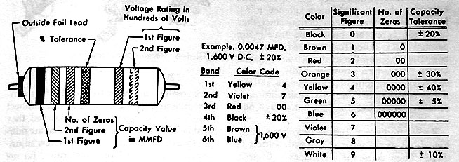
The following diagram from an old service manual shows how to
interpret color bands on round molded paper capacitors. (Click the small image to see a bigger view
that you can print.) In the example given in the diagram, bands of the colors yellow-violet-red
indicate a capacitor of the value .0047 mfd. A capacitor with the colors
yellow-violet-orange has the value .047 mfd, and so on.
Do not confuse molded paper capacitors with carbon resistors, which are also color coded.
Resistors are much smaller and their background coloring often is dull brown rather than shiny black. You can easily
confirm that a part is a capacitor by checking for resistance across its leads. Remove one lead from the circuit to test the part. Compare
the observed resistance on your meter with the predicted value indicated by the striping on the part.
|
|
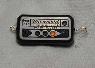
Flat molded paper capacitors show their values in colored coding dots, or less often, by values stamped into the case.
|
The capacitor shown in the previous photo has three colored dots, which
indicate the value according to the 1-2-3 scheme shown in the diagram for round
molded paper capacitors. For example, if the dots were colored
yellow-violet-red, the capacitor's value would be .0047 mfd as in
the previous example. The
molded arrow shows the direction in which to read the dots (in this case,
from left to right).
|
|
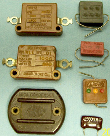
Mica capacitors also show their values in colored coding dots.
|
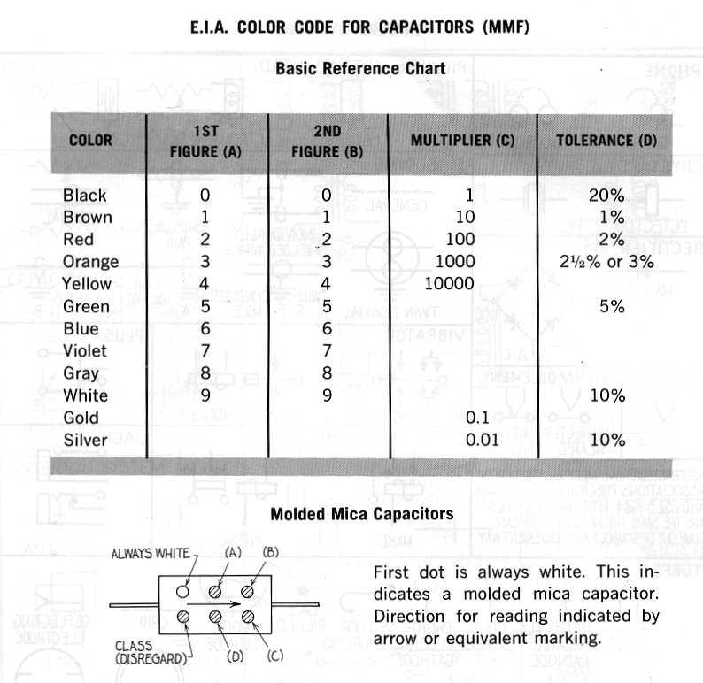
Mica capacitors rarely fail, but occasionally you'll find a bad one. The following
diagram explains how to decode the common "six dot" scheme used in many
micas.

For other color coding schemes, try this Google
search.
Electrolytic capacitors, housed in large metal or cardboard tubes, usually have their values
printed on the case.

|
Single section capacitor. Used in tone controls and other applications.
Values normally printed on case.
|
Single section electrolytic capacitors require little explanation. Simply replace them with new units
that have equivalent voltage and capacitance ratings. Some single electrolytics have rather low
voltage ratings, such as 50 volts.

|
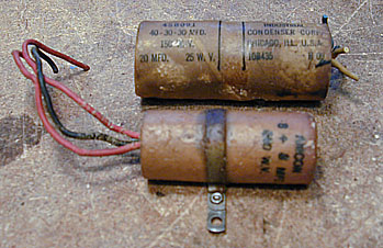
Multi-section cardboard. Often used as filters in a power supply.
Mounted horizontally under the chassis.
Contains two or more capacitors sharing a common ground connection. Values usually printed on
case and keyed to color-coded wires.
|
Multi-unit capacitors in a cardboard tube are often found in cheaper radios.
The case will have three or more colored wires coming out of one end.
One wire, usually black, will be the common negative connection.
The other wires will be the positive connections for each capacitor.
The case often is labeled with the capacitance and voltage ratings
for each capacitor. If those labels are absent, you will need to consult the radio's
schematic diagram.

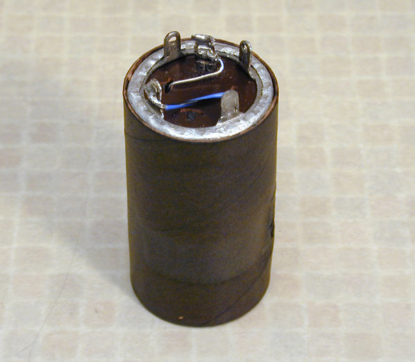
|
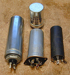
Multi-section vertical mount. Often used as filters in a power supply. Mounted vertically
on top of chassis. Contains two or more capacitors sharing a common ground connection. Values usually printed or
stamped on case and keyed to shapes on terminals at bottom. Case usually metal, occasionally cardboard.
|
Multi-section capacitors mounted in cans above the chassis are found in better-quality radios.
The values are either printed or stamped on the side or top of the can.
The bottom of the can often has metal terminals rather than colored wires. Small geometric shapes on the side and
bottom of the case tell you which terminal belongs to which capacitor. By convention, these shapes are a
square, a triangle, and a semicircle. (In older radios, the can may lack coding and you will
have to consult the radio's schematic to determine what each wire is connected to.)
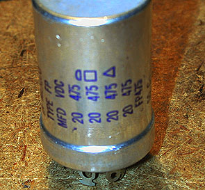
The following photo shows the value markings on the side of a four-unit metal-cased capacitor. Note the semicircle, square, and triangle
shapes.

The unit shown above contains four capacitors, each 20 mfd in value and rated for 450
volts. In this case, all the capacitors happen to have the same capacitance and voltage
ratings, although that is frequently not the case. As the photo shows, the first three capacitors
are marked with semicircle, square, and triangle shapes, respectively. The fourth has
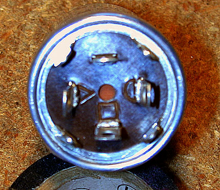
no marking. The next photo shows the underside of this capacitor.

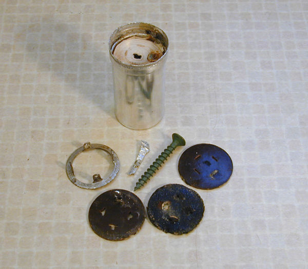
Seen from underneath, the capacitor has four terminals. Three are marked with the
semicircle, square, and triangle, while the fourth has no marking. These four terminals
are the positive (+) connections for each of the four capacitors.
As with the cardboard multi-capacitor unit, all of the capacitors share a single negative (ground) connection.
In this instance, it is the metal case itself which forms the ground connection.
The case has metal tabs which fit into slots in the chassis. To install this
unit, you slip the tabs through the slots, twist them about one-quarter turn
to secure the can, then solder one of them (it doesn't matter which) to the
chassis to ensure a good electrical connection to ground.
Certain other metal can capacitors are insulated from the chassis
and have a separate terminal for the ground connection. These
have an insulating washer between the can and the chassis. Don't
forget to put the washer back when replacing such a capacitor.
If a metal capacitor can has an outer cardboard sleeve, that's a sign that
its can has a higher voltage potential than the chassis. The insulating sleeve
protects against inadvetent shocks; if you remove it, be sure to replace it when you're done.
Choosing New Capacitors
Each capacitor has two values: a voltage rating and capacitance value. Both are important. The general rule for replacing
capacitors is to use values that are equal to or higher than the originally-specified values.
Voltage rating tells how much voltage the capacitor can withstand. Tube radios use high
voltage, so for safety reasons the voltage rating of the replacement must be equal or higher
than the original.
It does no harm to exceed the original rating somewhat. For
instance, it is fine to replace a 250-volt rated capacitor with a 450-volt
one. Almost all of the capacitors that I buy are rated for 450 volts.
A few capacitors may require a higher voltage
rating, such as 500 or 600 volts. Don't waste money buying capacitors with
voltage ratings vastly higher than the originals. Your radio will not work any
better with 1000-volt capacitors than with 450-volt units.
Capacitance value indicates how big an electrical charge the capacitor can store.
This value should also be equal or higher than the original, as explained more fully in the
two following sections.
Choosing Values of Non-Electrolytic Capacitors
For small, non-electrolytic capacitors, the capacitance value of the new cap should be the same as the original,
with a margin of error of about 20%. It is OK to "round off" odd values. For instance,
if the original is .05 it is fine to use .047 to replace it. The difference between .05 and .047 is only .003,
less than 20% of the original value. Likewise, you can replace
a .02 capacitor with .022, and so on.
The 20% margin-of-error rule works because most old radio components were manufactured within a tolerance of
about plus-or-minus 20%.
That is, a capacitor marked as .02 mfd could have an actual value as low as .016 (20% below the marked
value) or as high as .024 (20% above the marked value). If you stay within 20%, you are well within the
performance criteria for the radio's original design.
In practice, the operating tolerances of most radio designs allow for even more variation
in small-capacitor values in certain circuits. An experienced repairman knows these circuits
by heart and knows when he can safely substitute a quite different value
than the original. If you already know that much about radio repair, you don't need to read
this article, however! If you are still in the non-guru ranks, you will never go wrong by
following the 20% rule.
Naturally, if you have the exact value on hand, you should go ahead and use it.
If nothing else, this will aid you (or a future repairman) in
identifying that component should it need further repair.
Certain applications call for a more precise capacitance value, and in those
cases the schematic and/or parts list will specify a smaller tolerance,
such as 5% or 10%. Be sure to choose your replacement with the same tolerance.
Who Made Up These Weird Capacitor Values?
Beginners sometimes wonder why so many capacitors (and resistors, for that matter) have odd
values such as .22 or .039. Why didn't they use .2 or .04 instead?
In the early days of radio, capacitor values were often specified in regular values such as .2 and .04,
but for technical reasons, the International Electrotechnical Commission later devised a system of
preferred values
that efficiently cover the commonly-used values in a world where components have a given tolerance.
That is why you'll see a 0-100 number progression such as
10-12-15-18-22-27-33-39-47-56-68-82. When shopping for capacitors, you may find that .047
caps are easier to find than .05 caps, because .047 is a preferred value and .05 is not.
If you have a very old schematic that calls for a regular value such as .02,
remember that .022 is functionally equivalent. Similarly, .047 is the practical equivalent of .05.
If you have trouble finding a capacitor with a "round number" value, look for
the nearest preferred value within 20% of that figure.
Choosing Values of Large Electrolytic Capacitors
For electrolytic capacitors, the same rules apply, except that you can safely
use a capacitance value that is considerably higher. In general, you can
go as much as 100% higher than the original capacitance value.
For example, when replacing a 10-mfd electrolytic capacitor in the radio's
power supply, it is OK to use a 20-mfd or 22-mfd replacement. Likewise, you
could replace a 20 with a 33. The higher
capacitance may do a marginally better job of removing 60-cycle AC
line "hum" from the audio output of the radio.
Don't get carried away. Higher-value electrolytics are
more expensive and won't improve the radio's sound.
Don't waste money on a 100-mfd electrolytic if
your radio sounds great with a 20-mfd unit! Increasing the value
too much may also raise the radio's
B+ voltage level beyond prudent limits.
Substituting for Unavailable Values
In a pinch, you can combine two capacitors to create one with the desired value.
Simply remember that when two capacitors are wired in parallel,
their values are added. When wired in series, their capacitance
values are reduced.
For example,
say that you need a .04-mfd capacitor, but all you have on hand are .02-mfd units.
Wire two .02s in parallel, and you now have a .04-mfd capacitor.
Likewise, wiring two 22-mfd capacitors in parallel creates a single capacitor of 44 mfd.
Conversely, wiring two .02-mfd capacitors in series produces a .01-mfd capacitor.
The capacitance is halved.
Wiring in parallel or series also affects the voltage rating of the
resulting capacitor.
For capacitors connected in parallel, the voltage equals the lowest voltage
rating of either capacitor. For example, wiring two 22-mfd/150-volt capacitors
in parallel results in a 44-mfd/150-volt capacitor. Both voltage ratings
are equal, so the resulting voltage is 150 volts. If you wire in parallel
one 22-mfd/150-volt capacitor and one 22-mfd/35-volt capacitor, the
resulting capacitor will be 44-mfd/35-volt. The capacitance is
doubled and the lower voltage rating is 35 volts.
For capacitors
connected in series, the voltage is added up. For example, wiring two 22-mfd/150-volt
capacitors in series results in a capacitor of 11 mfd and 300 volts. The
capacitance is halved and the voltage is doubled.
Observe polarity when combining electrolytics. When wiring them in parallel,
wire both positive ends together and both negative ends together. When
wiring them in series, connect the positive end of one capacitor to
the negative end of the other.
Here's a real-world example. I needed a .25-mfd capacitor rated for 200 volts.
Not having that exact value, I wired in parallel a .22 and a .033, both rated
for 630v. The result is a .253-mfd/630-volt capacitor, which worked perfectly.

Incidentally, these rules work exactly the opposite for resistors.
Wiring resistors in parallel reduces the resistance,
while wiring them in series increases it.
What Type of Capacitor Should I Buy?
In the non-electrolytic category, there are several types of modern capacitors, such as polyester film,
polypropylene film, metalized polyester, and so on.
It makes no practical difference
which of these types you choose, as long as the capacitance and voltage ratings
are appropriate. New capacitors—even the cheapest ones—vastly exceed the
originals in performance and reliability, so don't waste your money buying expensive,
super-audiophile-quality replacements. The circuitry in your old set is not sophisticated
enough to respond to such subtle differences.
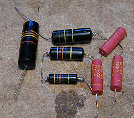
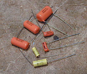
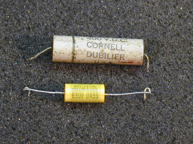
The next photo shows an assortment of new non-electrolytic capacitors, ranging
in value from .0015 to .01 mfd. The orange ones, known as "orange drops," were a traditional
favorite with restorers. The yellow cylindrical caps are smaller than orange drops and
are a great choice for cramped quarters. Cylindrical caps are also cheaper than the
orange drops. Both are more than adequate for any radio or TV restoration.

In the electrolytic category, many old radios use multi-unit capacitors, as mentioned earlier.
These are two or more capacitors inside a single can or tube.
It is sometimes possible to order replacement multi-unit capacitors that exactly
match the original values. However, new multi-unit caps can be quite expensive
and it may be hard to find the right value assortment in one container
(one supplier of such caps is Hayweed Hamfest).
It is economical to replace a multi-unit capacitor with individual capacitors
of the desired values. For instance, if your original can contained capacitors of
20 mfd, 20 mfd, and 30 mfd, you can replace it with two new 22-mfd capacitors
and one 33-mfd unit. Your radio will work exactly the same whether you use a multi-unit
can or individual caps. The next photo shows typical new electrolytics, ranging in
size from 5 mfd to 100 mfd.

If you plan to fix many radios, you can save money by buying an assortment of
capacitors of common values. Some merchants, such as Antique
Electronic Supply, offer a "kit" of common caps at a good discount. You
can usually save money by ordering 10 or more of a given value, as well. The most common
values needed in old radio repair are .01, .02, .05, and .1 mfd for non-electrolytics,
and 10, 20, 30, and 40 mfd for electrolytics.
You will use many more small
non-electrolytic capacitors than large electrolytics. For a typical five-tube radio,
you might replace a couple of electrolytics and half a dozen of the smaller capacitors.
Capacitors are not expensive. The electrolytics that you'll need will usually cost from one to five
dollars each. Most non-electrolytics cost less than a dollar.
Recapping the Grundig radio shown at the beginning of this article cost me about ten bucks.
Replacing Non-Electrolytic Capacitors
Now that you have the parts you need, let's install the new ones! Replacing small
capacitors is the simplest operation, so we'll look at that first, then turn to the
electrolytics.
Note, however, that in practice it's preferable to replace the
large electrolytics first. That will help eliminate power-supply problems and
simplify testing the radio while later replacing the small caps.
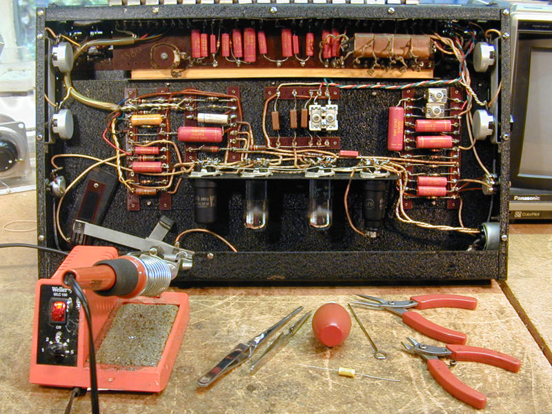
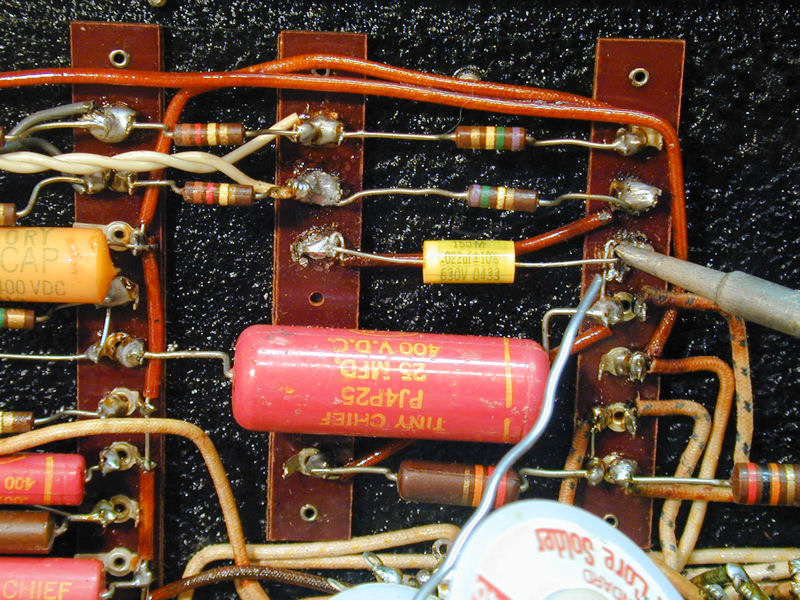
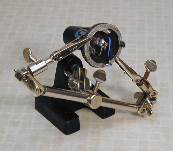
Replacing a capacitor requires a wire cutter, small pliers, and a soldering iron.
Another nice thing to have is a "solder sucker," a small rubber bulb
with a heat-resistant tube at one end, or a metal tube with a spring-loaded
sucking mechanism. I'll illustrate this section with photos from the restoration
of my Clavioline. The
basic method is the same for every vintage tube device.

I strongly recommend that you replace only one capacitor at a time and doublecheck the
wiring of each replacement against the schematic. That way, if
you make a mistake, it will be easy to correct. If you replace several capacitors
at a time, it could be much harder to figure out where you went wrong! I often
take notes, as well, writing down each capacitor's value and part number when it
is replaced, or checking off the capacitor on the schematic and parts list.
Before replacing anything, of course you must unplug the radio from the wall and remove the
chassis from the cabinet. Use a small plastic bag to hold the chassis mounting screws, knobs, and any other parts.
Turn the chassis on its side or back so that it will lie still while you work. Be careful
not to damage delicate parts when you turn it over. Don't rest the radio upside down on its
tubes. If necessary, you can prop up one side of the chassis with a book, small block of wood, etc.
My Midwest DD-18 article describes a simple holder
for large and heavy chassis.
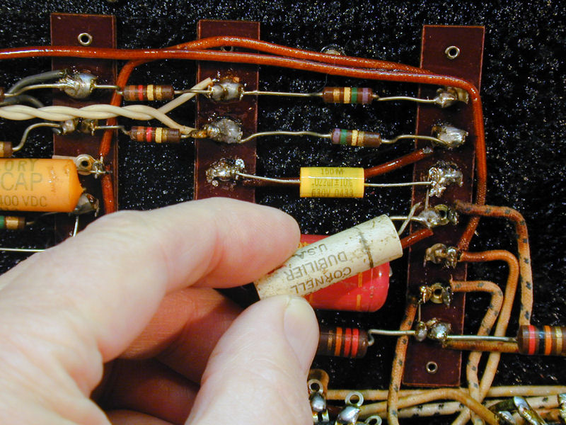
Some purists go so far as to hide new capacitors inside the shells of the small
non-electrolytic paper capacitors. This preserves the original appearance, but it
is rather tedious. I have done this only in a few cases, for my most valuable radios.
If you are interested in doing this, read the restoration articles for my
Sparton Bluebird or Colonial Globe.
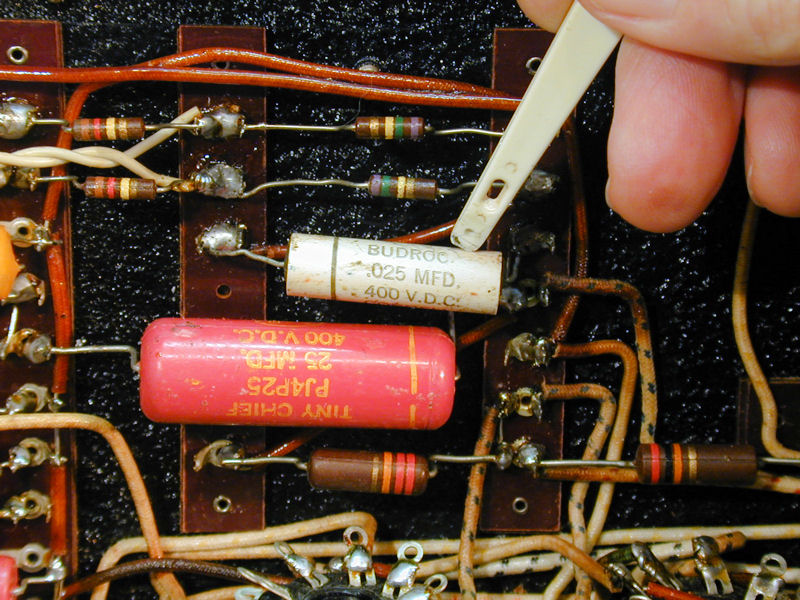
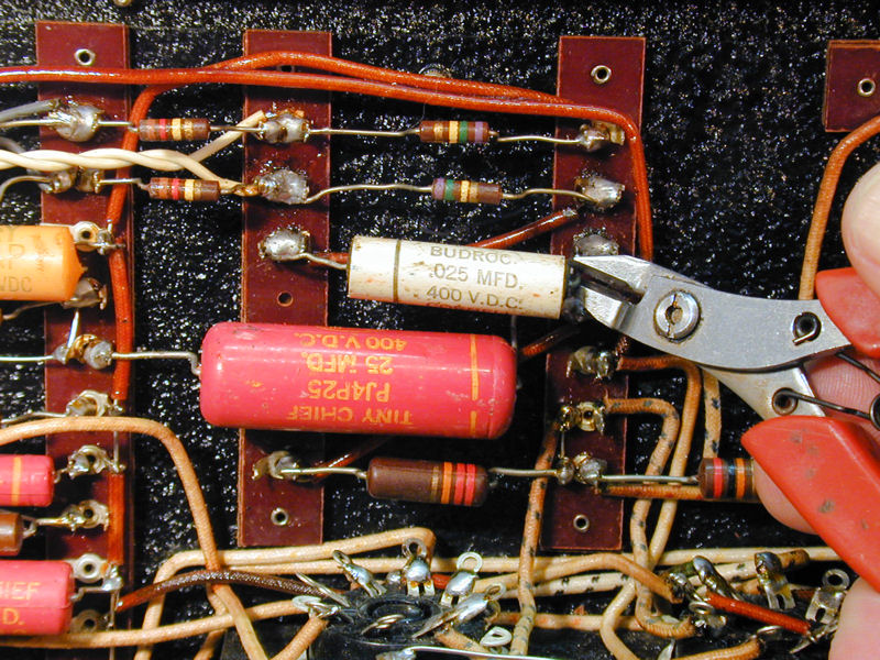
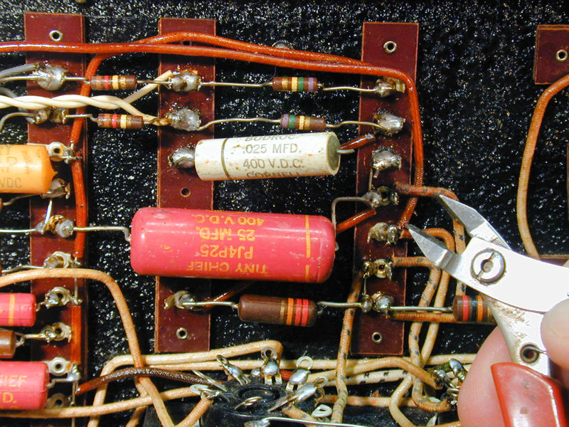
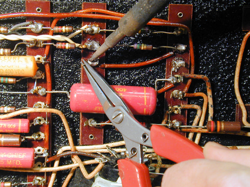
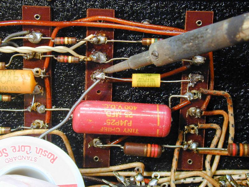
Step 1. Remove the Old Capacitor
Using your wire cutters, snip the leads of the old capacitor about one-half inch
from the terminals where they are connected. Leaving a little "tail" on the
snipped wire makes it easier to remove. Set the old capacitor aside.


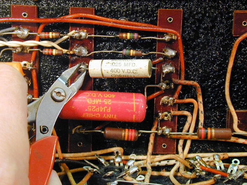
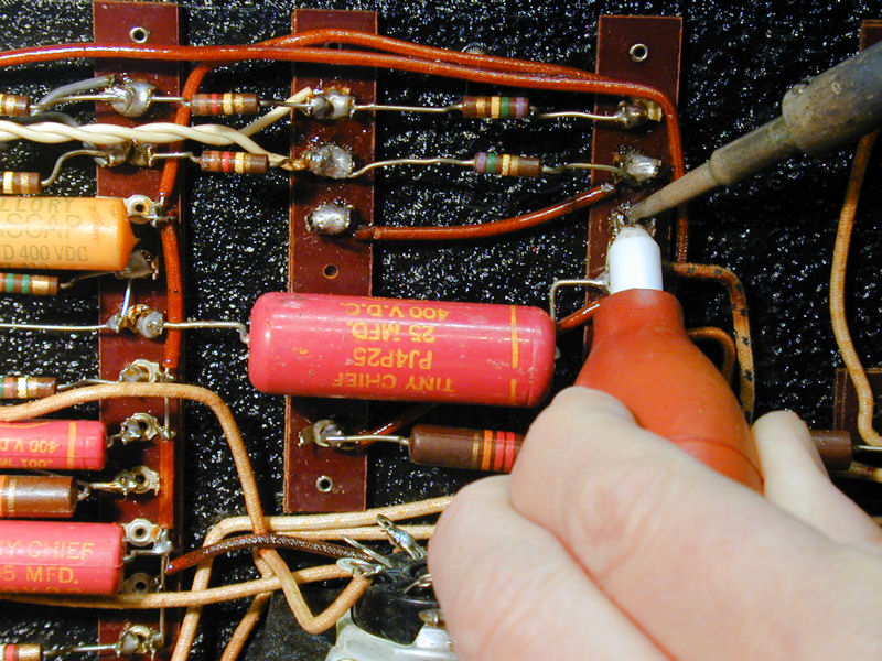
Use your soldering iron to melt the solder on the terminal, suck the excess solder
from the terminal, and use your thin pliers to remove the
snipped wire tail from the terminal. You may need to unbend the tail a bit to
work it free. If it is very firmly crimped onto the terminal, try snipping the bent
portion to free it in two pieces.


Sometimes, a thin implement such as a nut pick or dental pick is handy for nudging the
snipped tail out of its lair. A round wooden toothpick may help to clean out little circular
holes in a terminals, since melted solder doesn't stick to wood.
If the snipped tail is attached to a pin of a tube socket, avoid using too much force
to pull it loose. You might yank the pin right out of the socket or even tear it in two.
The same goes for other components that are attached to the same terminal. Old carbon
resistors are brittle and will break if handled too roughly.
Once in a while, a capacitor will be mounted in cramped quarters, so that you need to unsolder
another lead or component to gain access. In such a case, make a note or draw a picture
so that you can reconnect everything correctly.
After you remove the snipped tail from the terminal, look carefully to make sure that
you didn't leave any bits of wire or solder crumbs in the chassis. Small bits of metal
can cause problems if they lodge in between two connections and make a
short circuit.
At this stage, the old capacitor has been removed and the terminals are clean.
Hint: if you do a great job of cleaning the old terminals, it may not be obvious
to the eye where the new leads should go. If you are interrupted at this stage in the
process, loosely stick the leads of the new capacitor into the terminals so that
you won't be scratching your head with puzzlement when you return. It's easy to
forget exactly where things went, after an hour or two. You can also temporarily
attach the ends of clip lead to the connection points as a reminder.
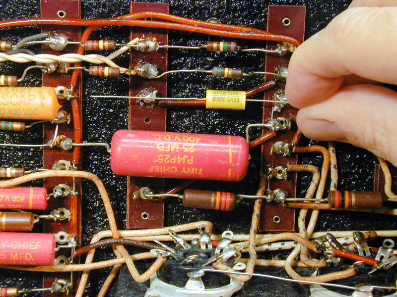
Step 2. Install the New Capacitor
It is good practice to test every new capacitor before installing it in the radio.
Modern capacitors are generally high quality, but every now and then a bad one
slips through. If you don't have a capacitor checker, you can at least test
the capacitor's resistance using a multimeter. The ohmmeter should show
infinite resistance on all scales. Any continuity is a sign of leakage
and a leaky capacitor must be replaced.
New capacitors usually have wire leads somewhat longer than needed. Your first
job is to trim these leads and bend them to fit the spot.
Hold the new capacitor
near the place where it is to go, bend the leads to fit, and then trim the excess
wire from the end of each lead with the wire cutters. Leave enough length on the
lead to allow for crimping it around the terminal. Again, be sure to avoid
leaving stray bits of wire inside the chassis.


If the terminal is the type with a hole, slip the end of each lead into the hole.
If you did not clean all the old
solder from the terminal, you may need to heat the terminal to soften the solder
before slipping in the lead. After the lead is through the terminal, carefully
bend it around the terminal. Before soldering the new capacitor in place, you want
to make sure that it has a solid metal-to-metal connection with its terminal!
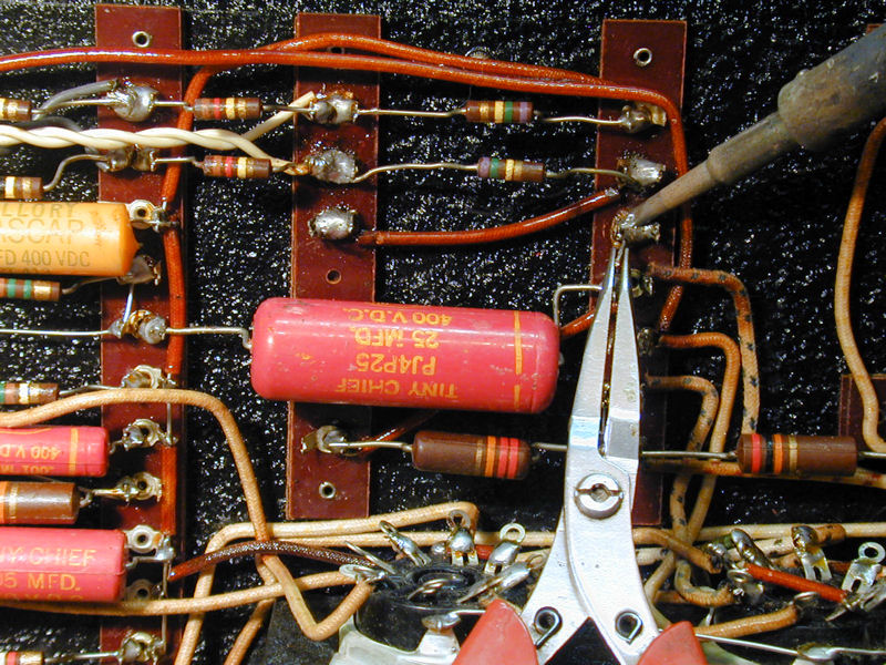
When both leads are securely crimped onto the terminals, heat each joint with
the soldering iron and apply new solder.


Apply solder to the joint, not to your soldering iron. If the solder doesn't melt when touching
the joint, then the joint is not yet hot enough. Don't jiggle the connection while the solder
is cooling. That can create a "cold" joint that is not reliable.
Sometimes, when a delicate component is connected to a terminal, I'll temporarily
clip a metal tweezer onto that component's lead, to act as a heat sink and
prevent overheating damage.
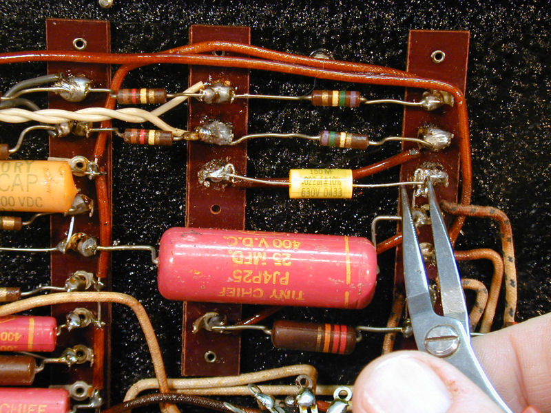
Step 3. Check Your Work!
After replacing the capacitor, doublecheck your work against the schematic to make sure that
you connected the right component to the right places.

If the radio or TV is in working order, I often turn it on for a quick test after replacing
each capacitor. Even professionals make absent-minded mistakes from time to time, and this
brief road test will reassure you that you haven't made things worse!
If your set doesn't work at all, you will obviously need to do some other diagnosis and
remedy the problem before turning it on. The "test after each replacement" routine applies
only to radios and TVs that are basically working in the first place.
Obviously, if you are testing the radio with the chassis exposed on your workbench, use extreme
caution to avoid getting a shock. Temporarily put the knobs back on their shafts before turning
it on. Don't touch anything except the knobs while the radio is plugged in. Unplug the
radio before resuming your recapping. An "AC/DC" type radio can give you a fatal shock
from its chassis when plugged in, even when its power switch is turned off.
That's all it takes! If you can replace one capacitor, you can replace 'em all, so go to it.
Replace the remaining paper or molded paper capacitors one by one until you reach the end of your list.
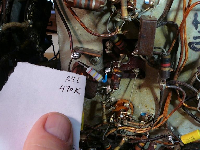
Step 3. Record Your Work
It's good practice to make a note of each replacement as you go along, to prevent confusion
and to make sure that you haven't skipped anything. I usually check off each part on the
schematic and parts list:


The component shown in those photos is a resistor, not a capacitor, but you get the
idea.
Digital photos are extremely useful, and since they're virtually free, why not take
a lot of them? I take detailed photos of every radio or TV chassis's underside before
starting work. If confusion arises later, those photos will show you how things were
connected before you started messing around. I take more photos from time to time
as my work proceeds, whenever I want to record something important.
Replacing Capacitors on Printed Circuit Boards
Starting in the 1950s, manufacturers introduced printed circuit boards. Instead of
wiring every component separately, the wiring was pre-applied to a board and
the component leads were soldered into little holes in the board.
Replacing caps on PC boards is usually not difficult, but you'll need to use slightly
different techniques. Those are explained in a portion of my Philco Miss America TV article entitled,
Replacing Caps on PC Boards.


Replacing Electrolytic Capacitors
The mechanics of disconnecting the old capacitor and soldering in the new one are the
same for electrolytic capacitors, so refer to the previous section for those basics.
Electrolytics are special in a couple of ways, however. First, their large
capacitance value means that they can store an electrical charge—enough to deliver
a painful shock—even when the radio is turned off and unplugged. Before touching the
leads of an electrolytic capacitor, discharge the cap by shorting its leads together
with an insulated clip lead.
Secondly, their large size introduces some complications in installing the replacements,
which we discuss in the following sections.
Most electrolytics contain metal foil and a paste, which dries out over time and causes
failure. In 1930s or earlier radios, you may find a "wet" electrolytic,
which contained a weak solution of boric acid rather than paste. You can read about wet
electrolytics in my Philco 60B restoration article.
To Hide Or Not To Hide?
When replacing large multi-unit electrolytics, you have two choices.
The simplest option is to disconnect the old can and
leave it in place for appearance's sake, then wire the new capacitors out of sight underneath
the chassis. The radio looks original from above and you will save a lot of time and effort.
This method was used in the Grundig radio shown at the beginning of this article.
The big blue components are new capacitors installed under the chassis.
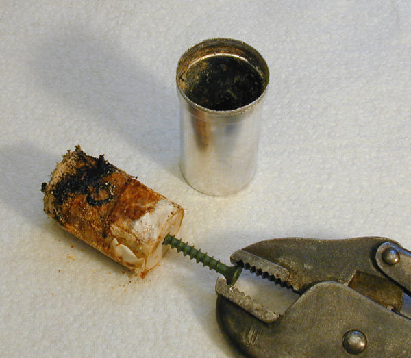
The second option is to "restuff" the can. You remove the old can, pull out its innards, hide new
capacitors inside, and reinstall it. This takes more work
and I do it only for special or valuable sets, or in the rare case where there's no room
for a new capacitor under the chassis.
This process is detailed in the articles for my
DuMont RA-113 and
DuMont RA-103 and
RCA CTC-11 televisions,
and Midwest DD-18 and
Hallicrafters SX-42 radios.


There are various types of can electrolytics, so the procedure used to restuff
will differ, accordingly.
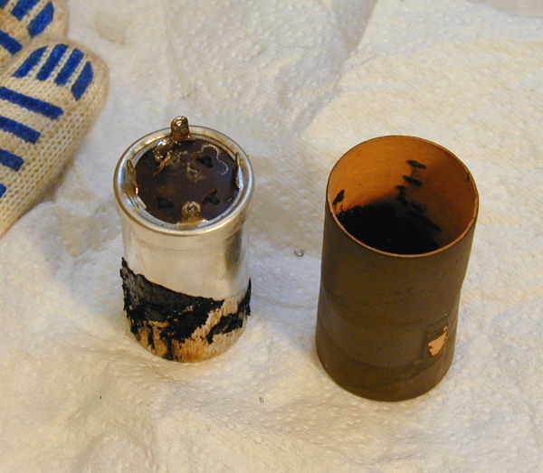
The previously listed articles show cans that are completely removed, stuffed, and
then replaced like before. An alternative is to cut the can above the
chassis, install the new cap leads through the old base, and then put the emptied
can back on. This technique is explained in my RCA CTC-7 TV article, in the
section entitled,
Restuffing
Electrolytic Cans on Undisturbed Bases.

Installing New Electrolytics
The first thing to remember about installing electrolytics is that polarity matters!
You must install them with the positive and negative leads in the right places.
If you reverse the leads, the capacitor may overheat and explode. Needless to say,
your radio will not work, either.
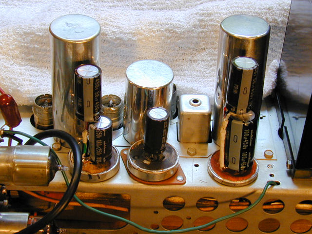
New electrolytics are always marked to indicate which end is positive and which is
negative. Most often, a band of arrows and minus signs is printed along
the length of the capacitor. The arrows point to the negative (-) end.
In the following photo, the negative ends of the larger capacitors are all to the right.
If you don't hide the new caps inside the original can, you must
decide how to mount them under the chassis. Many sets have enough "elbow room"
underneath to fit in a couple of additional components. Some battery portables, however,
pack components tightly into a small chassis and may have little if any spare room.
The important factors are to mount the new capacitors securely and to
insulate all connections.
Multi-section cardboard capacitors are often mounted on the chassis with a metal clamp.
In the next photo, the clamp has been removed from the top unit.
If the clamp is attached with a screw, you
might be able to reuse it as a mounting point for your new capacitors. When the clamp is riveted on,
I usually cut through the band with a Dremel Moto-Tool and cutting wheel (don't
forget the safety glasses!) and discard the whole business.
As mentioned earlier, some times the metal can itself comprises the ground connection for
a vertically-mounted unit (see following photo). If you replace such a can with a compatible metal-cased unit,
you will need to make sure that the new can is well grounded to the chassis.
The can of a vertical-mount unit does not always provide the ground connection, however.
In the following photograph, the middle unit in the bottom row has a can that is electrically
isolated from the chassis. The common ground connection is made
through a terminal or wire coming out of the can's bottom.
Note: The "ground" connection point in a radio is not always the chassis.
In many radios with transformer-type power supplies, the chassis acts as
the common ground point. In others, however, including many transformerless
AC/DC radios, ground is "floating," meaning that it's a separate
circuit not connected to the chassis.
When you replace electrolytic capacitors, take care to connect the negative lead of each new capacitor to precisely the same
location (or terminal) at which the negative lead from the old part was connected in the chassis.
When you wire up the new capacitors, keep the leads as short as practical.
Depending on the layout under the
chassis, some times it will work better to remove the old capacitor leads completely
and solder the new leads directly to the appropriate terminals. In other cases,
where the old leads were quite long but still in good condition, it is acceptable
to solder the new capacitor leads to the old leads. You can insulate
the new connection with a short piece of plastic heat-shrink tubing.
If the underside of the chassis is cramped, you may need to mount the new capacitors somewhat
distant from the original location. Look carefully at your schematic and at how things are
connected under the chassis. As long as your capacitor connects to the right points in the
circuit, its physical location might not be too critical.
For example, if the common negative point is the chassis itself, there may be a closer ground
connection available, making for a neater chassis layout when you are done.
As a rule, position your new electrolytics as close as possible to the original connection
points. If you relocate a power-supply capacitor, don't place it next to RF tuning circuits or high-frequency
circuits, where it may create RF interference and cause buzzing or other misbehavior.
Avoid locating the new capacitor in a place that blocks access to other components. Some
day in the future, you or someone else might need to make more repairs, so don't
make that job more difficult.
Sometimes, you can use a plastic tie to hold the new capacitor in place. For
instance, you could tie the body of the capacitor around a nearby bundle of wires.
Don't use a plastic tie to go around uninsulated leads or any component that gets hot.
If the leads of the new capacitor are short enough, they alone may hold the capacitor in place. I have also used
metal clamps or even a dab of epoxy glue to secure new capacitors. Don't use hot
glue for this purpose; the heat of the radio may soften the glue and allow
the capacitor to fall loose.
No matter how you install the new capacitors, use spaghetti tubing or
other insulation as needed, to prevent short circuits.
The hot ends of these capacitors carry comparitively high voltage;
you will be sorry if one of them slips loose and fries other parts.
While you are replacing electrolytics, it is
also an excellent time to replace the power and cord and install a fuse on the
power line if your radio does not have one. A fuse is an important safety feature
which many old radios lack. A 1-amp fast-blow fuse works fine for most radios. Install it
on the "leg" of the power cord which is switched by the on/off switch.
If you replace the electrolytic capacitors in the power supply circuits and your
radio still emits a loud hum that is not affected by the volume control,
carefully check your wiring against the schematic diagram. It is a common beginner's
mistake to wire an electrolytic backwards (with positive and negative reversed).
Mounting Electrolytics on a Terminal strip
Sometimes, when installing electrolytics separately under the chassis, the
best solution is to mount them on a terminal strip. The strip is
secured to the chassis with a screw or a solder joint. The installation
is very secure and it will look tidy and professional.
To learn how, see
Mounting Electrolytic Capacitors on a Terminal Strip in my article about
restoring a Philco Miss America TV television.

Mounting Electrolytics On a Can Base
A further variation is to install new electrolytics on the
base of the original can. Earlier, in the explanation of restuffing,
I listed an example in which the old can tops would be put back
in place to preserve the can's original appearance.
If you don't care about the appearance, or the new caps can't
possibly fit inside, you can simply toss the old can. For an illustration, read
Mounting
Electrolytic Capacitors on a Can Base in my Philco Miss America
article.

It's Easier Than It Sounds!
Recapping is easier than this article makes it sound. I have included many details to explain the process
clearly, but with a little practice you will find that you can recap a simple radio in one evening.
Even if the radio "worked" before you started, you will often find
that replacing the capacitors improves its performance. You will certainly improve its reliability.
The new capacitors that you installed might last your lifetime!
Old radios can suffer many other ills, of course. If replacing capacitors doesn't bring
your set back to life, you will need to do some further diagnosis, which goes beyond
the scope of this article.
Our Restoration section has many
articles with further information about radio and television repair.
|