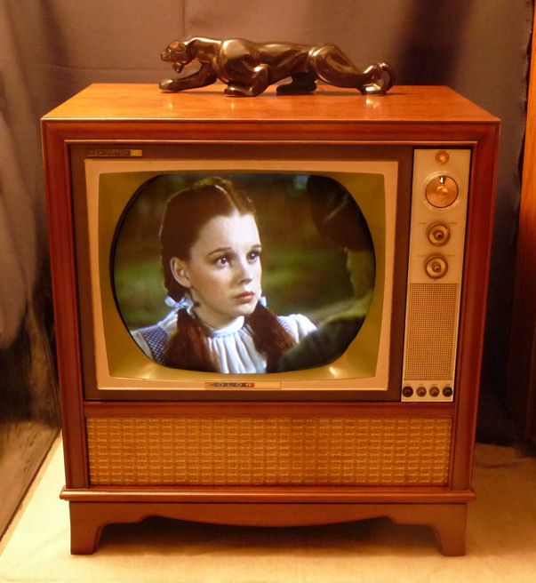
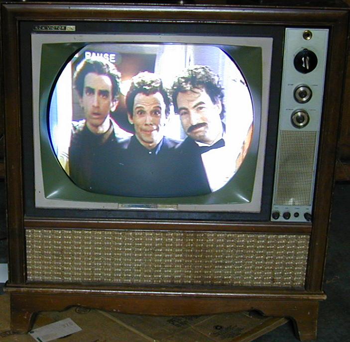
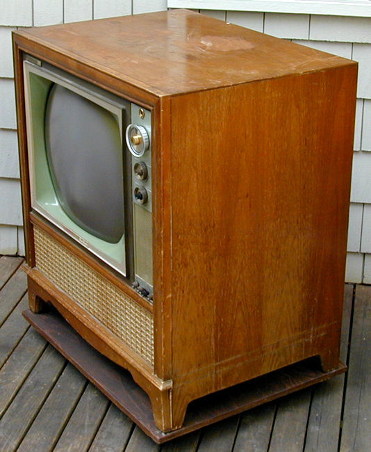
RCA Model CTC-11 Color Television (1962)


This RCA CTC-11 was my first color television restoration.
Collectors call these early color TVs "roundies" because their
picture tubes are round rather than rectangular.
I hadn't been looking for a roundie, but this deal was too good
to pass up. The owner contacted me by email, offering to trade it for
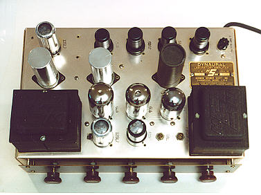
my little Scott 210-B mono amplifier.

I liked the Scott, but I had never used it much, and it had cost
me only $7 in the first place. After restoring dozens of radios and several
black and white TVs, a color TV would give me something new to learn.
Pickup
The TV was located about 100 miles away. Before completing the trade,
the owner showed me that the TV worked, with a decent picture. He
had owned the TV for a number of years but never really used it.
A high school teacher had given him a new picture tube, so that
vital part should be fine for a long time.
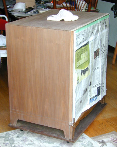
It took two men, the owner and his
Dad, to load it into the back of my wife's SUV. The only way it would fit
was lying on its face (with all knobs removed, of course), with about
1/4 inch of space between the TV cabinet and the SUV's ceiling. The
cabinet back was missing, so great care was needed to avoid snapping off the
neck of the picture tube.
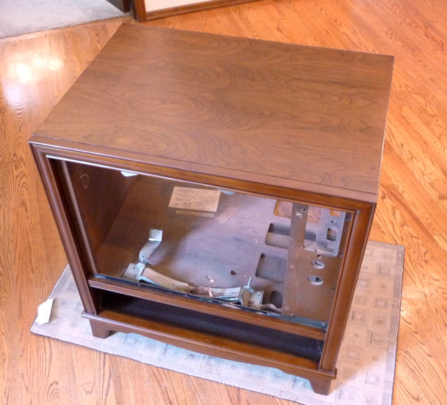
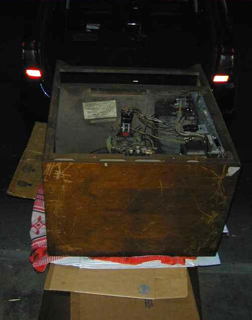
When I got home after dark, nobody else was there to help me, but I
was itching to get the TV out. The television was
much too heavy for me to lift myself. The next photo shows
how I extracted it. I propped an old door on the SUV's tailgate,
covered it with cardboard and an old blanket, and very slowly
slid it down the makeshift ramp. If somebody else had tried this,
I would have called them nuts, but eventually the TV was standing
upright in the garage.
The television was filthy, with a scarred cabinet top, but
I had dealt with such things before. The question was whether the
electronics were restorable.
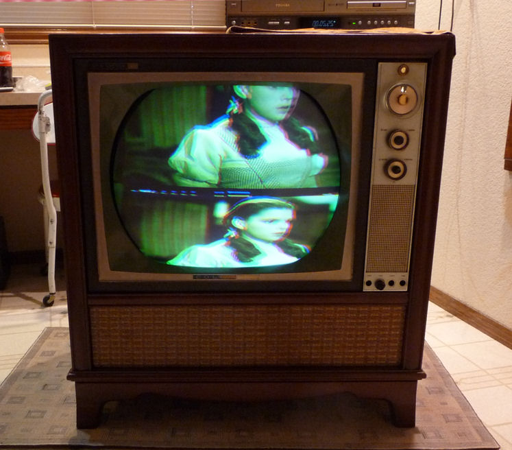
First Look
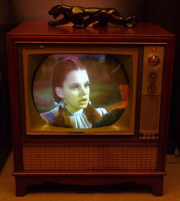
The owner had played the TV with no fireworks, so I
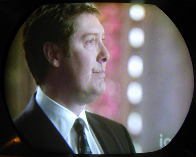
figured it was not too risky to turn it on. Here are screen
shots of the unrestored set, using a rabbit ear antenna as
well as a DVD source.
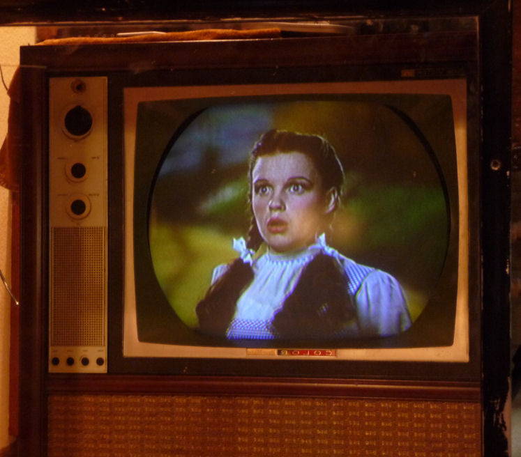
An experienced technician will instantly see various defects
in the image, but the good news was that the TV was basically
functional. The picture was bright and colors such as
flesh tones were rendered pretty well.


Some of the defects, such as color purity, are simply a matter
of adjustment after the electronics are restored.
With any luck, I should be able to restore it by replacing the
power supply electrolytic capacitors, cleaning the controls,
and then adjusting for best picture. The cabinet top will need
to be stripped, but I can just touch up the rest.
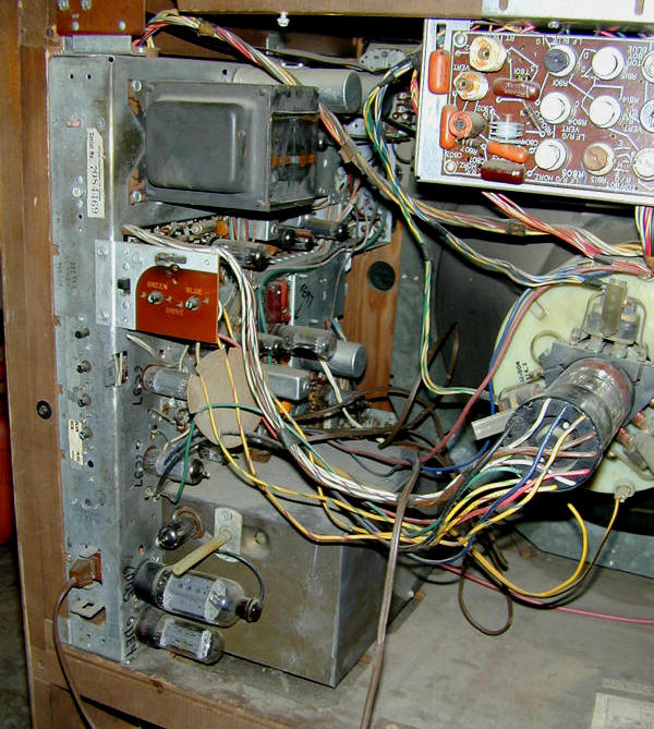
Electronic Restoration
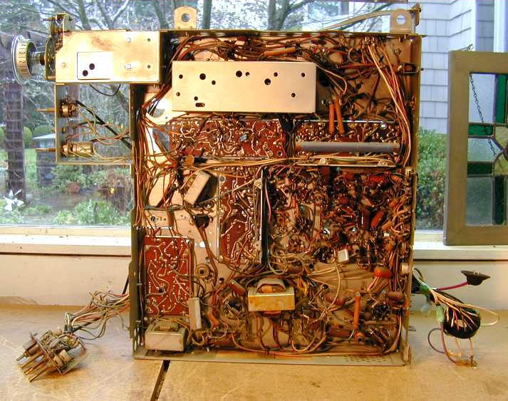
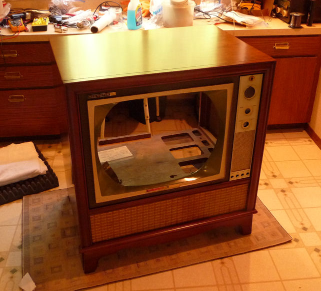
Here is my first look at the television's innards. The main chassis
is mounted on its side. The convergence subchassis is mounted above
the picture tube. A little subchassis (not visible here) projects
through the front of the cabinet and holds controls for vertical,
horizontal, contrast, and audio tone adjustments.

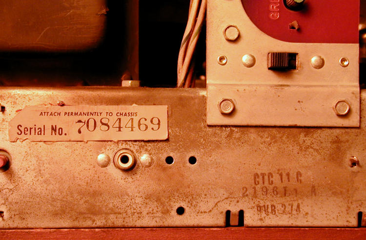
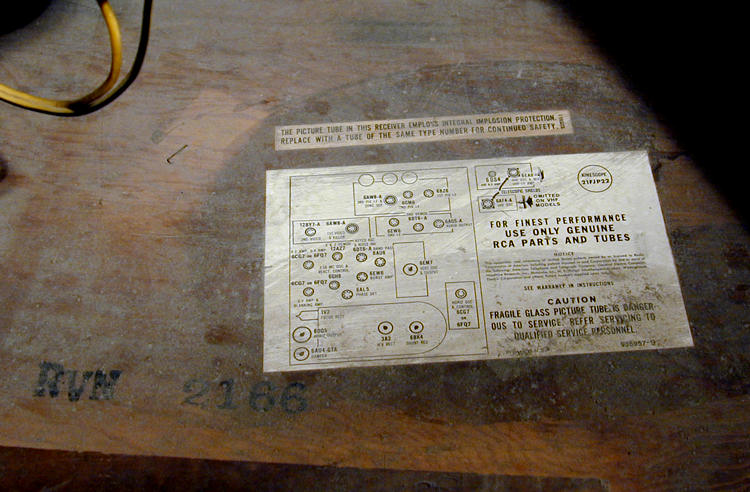
Version information appears on the chassis and cabinet.


The CTC-11 uses 25 tubes and one 6CW4 Nuvistor.
| Tube |
Type |
Function |
| V1 |
6BZ6 |
1st Video IF Amplifier |
| V2 |
6GM6 |
2nd Video IF Amplifier |
| V3 |
6AW8A |
3rd Video IF / Sync. Sep. |
| V4 |
6AW8A |
Video Amp. / Color Killer |
| V5 |
12BY7A |
Video Output |
| V6 |
6DT6A |
AGC Keying / Noise Inverter |
| V7 |
6EW6 |
Audio IF Amplifier |
| V8 |
6DT6A |
Audio Detector |
| V9 |
6AQ5A |
Audio Output |
| V10 |
6EM7 |
Vert. Mult. / Vert. Output |
| V11 |
6CG7 |
Horizontal AFC / Horiz. Osc. |
| V12 |
6DQ5 |
Horizontal Output |
| V13 |
6AU4GTA |
Damper |
| V14 |
3A3 |
High Voltage Rectifier |
| V15 |
1V2 |
Focus Rectifier |
| V16 |
6BK4 |
High Voltage Regulator |
| V17 |
6AU6 |
Chroma Bandpass Amplifier |
| V18 |
6EW6 |
Burst Amplifier |
| V19 |
6AL5 |
Chroma Sync. Phase Detector |
| V20 |
6GH8 |
Chroma Ref. Osc. & Control |
| V21 |
12AZ7 |
X Demodulator / Y Demod. |
| V22 |
6CG7 |
R-Y Amplifier / B-Y Amplifier |
| V23 |
6CG7 |
Horiz. Blank. Amp. / G-Y Amp. |
| V24 |
21FBP22 |
Picture Tube |
| V201 |
6CW4 |
RF Amplifier |
| V202 |
6EA8 |
Mixer / Oscillator |
The Sams service manual for this TV is
Set 550, Folder 2.
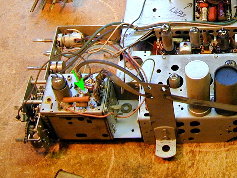
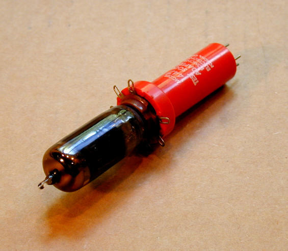
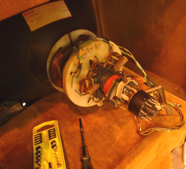
Nuvistors and New Vistas
The CTC-11's 6CW4 "nuvistor" is actually a tiny tube.
Introduced by RCA in 1959, nuvistors were one of the last developments in tube
technology; like the recently-developed transistor, it was smaller and
more rugged than a conventional tube. In this photo, the arrow points to the
nuvistor used in my CTC-11 tuner:

The nuvistor is much smaller than the nearby 6EA8 tube, which is the all-glass
"miniature" type popularized after World War II.
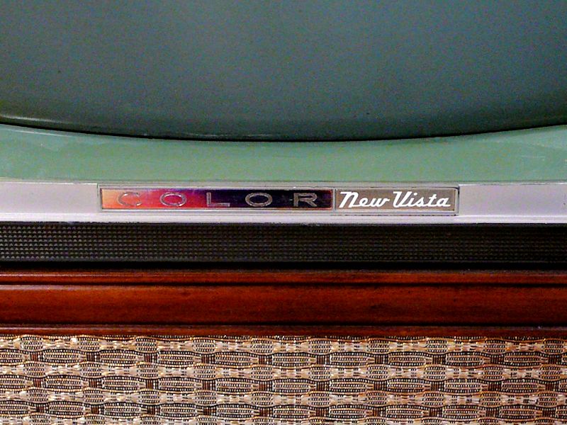
RCA color TVs of the early 1960s sported a "New Vista" badge
under their screens, with a COLOR sign that changed colors
as you moved around the room. Here's a view of my badge:

The "New Vista" marketing term played on the word nuvistor
and dramatized the new world of color television viewing. RCA used it extensively in
its 1960s TV advertising.
You can read much more about nuvistors in the article
"Nuvistor Valves" by Stef Niewiadomski.
Cleaning Controls and Tube Pins
Here is the unrestored chassis removed from the cabinet. The 21-inch picture tube
is very heavy and normally would not be removed for service.
Notice the four cylinders with flat tops.
These contain electrolytic capacitors—a total of ten capacitors
among the four cans. We'll return to these presently.
After doing some initial cleanup, I tested the tubes and cleaned
their pins. Not surprisingly, since the TV worked, they all tested good.
I also cleaned the controls (volume, etc.) by spritzing DeOxit cleaner
into their cases and working the controls back and forth several times.
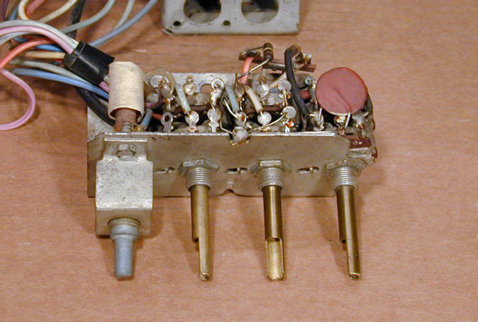
Below is a small sub-chassis that contains seven controls. Four of
them protrude through the TV's front panel and have knobs: horizontal hold,
vertical hold, contrast, and color tone. (The horizontal hold control is
an adjustable coil that requires no cleaning.)

The other three potentiometers on the sub-chassis control
killer threshold, vertical linearity, and height. They are accessible
with a very thin screwdriver blade through the hollow shafts of the three
pots listed earlier.
The CTC-11 contains more potentiometers—there are 26 in all—but
the remaining ones are for adjustments such as convergence or high
voltage level, which I don't want to touch at this stage.
I knew the tuner needed cleaning, as well. Tuning was pretty hit and miss during
the initial tryout. Some channels needed jiggling to get a stable
picture with correct colors.
The tuner comprises another sub-chassis, mounted on the main chassis with three screws.
Removing the RF output cable (it has an RCA jack) lets you swivel the tuner around
without unsoldering any of the other wires.

You remove two metal shields to expose the tuner innards.
The big shield slides downward. You may have to help
it get started by gently pushing with a screwdriver blade at the top.
A smaller shield is mounted near the front with two twisted metal tabs at
its top. Carefully bend the tabs straight so that they can move
through their slots, allowing the shield to slide down and off.
With access to the phenolic wafers, I carefully
sprayed a little DeOxit on each contact assembly and switched
the tuning knob through all of the channels a number of times.
Capacitor Replacement
Although the original electrolytic capacitors were working—at least for the moment—I
decided to replace them for safety and reliability.
That's easier and cheaper than replacing an expensive part like a power
transformer if one of them fails. Besides, healthy capacitors are
vital for a healthy power supply.
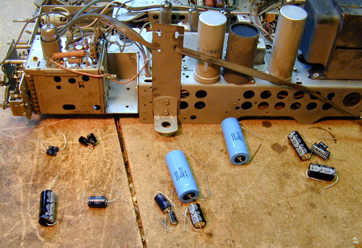
Here are thirteen new electrolytics, ready for installation.

Sometimes you can replace multi-section electrolytics by
disconnecting the originals and wiring new caps under the chassis.
The area under these cans is cramped, however, so I "restuffed"
two of the cans (holding a total of five capacitors), removing the old innards and
putting fresh capacitors back in their place. I left the old
cans intact on top of the chassis, to preserve its original appearance.
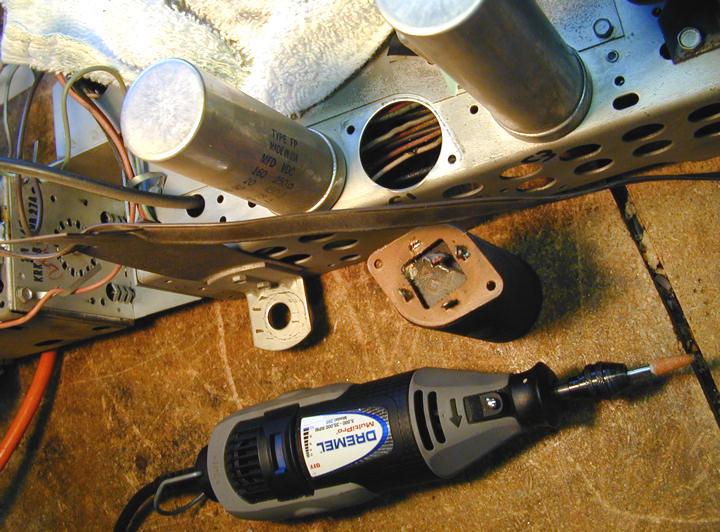
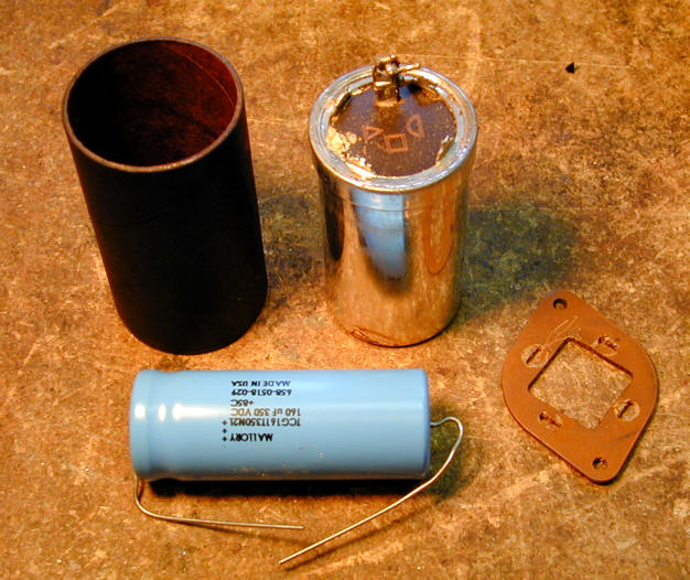
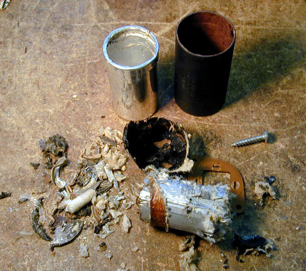
Here's a "wordless workshop" on how I restuffed one of them: C1, which
contains a single electrolytic in its can. The replacement was a little
too long, but I made it fit.


The small capacitors in this TV are ceramic or dipped Mylar types,
which are usually reliable, so I left them alone unless
I had a specific reason to replace one. My article on
capacitor replacement has much more
on the general topic.
Audio Troubles
With fresh electrolytics installed, I cautiously powered up the
TV and was delighted to see a good picture. The only thing
missing was the sound! All I could hear was a faint background
hiss with the volume turned all the way up.
I first checked the obvious. Perhaps I had broken a speaker
connection when taking the chassis in and out of the cabinet
or (shudder!) miswired one of the electrolytics affecting the audio section.
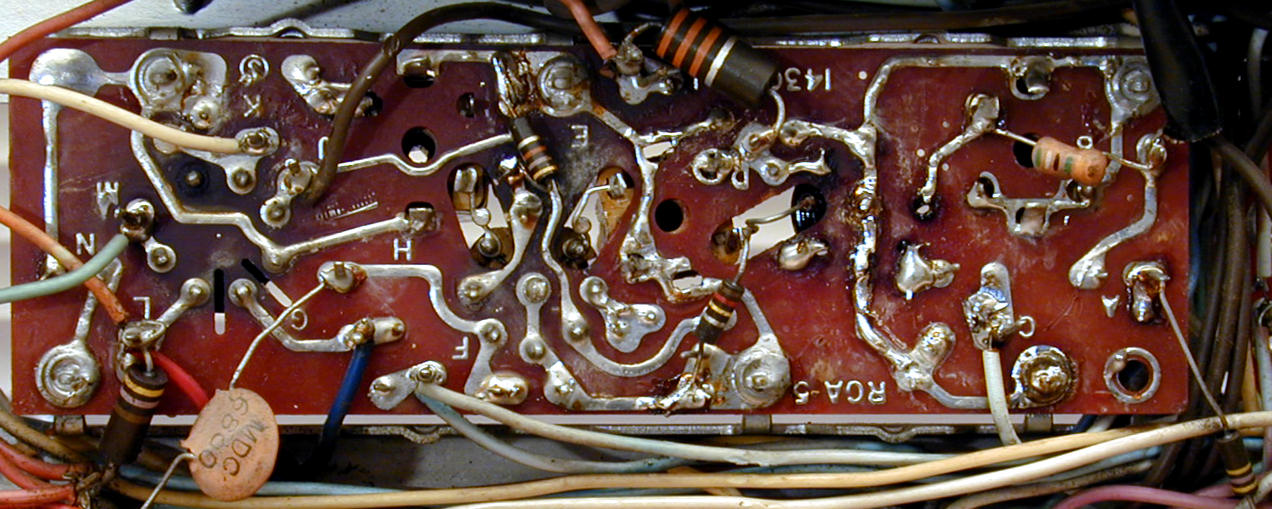
No smoking guns appeared, so I began trying to diagnose the
problem. The CTC-11 audio circuit is conventional and
not very complicated, using three tubes. Here's the audio
portion of the schematic and the audio board, top and bottom.
From left to right in the top view are the sockets for the 6EW6,
6DT6A, and 6AQ5A tubes.
Using a basic repairman's test, I found that a live soldering iron
touched to the wiper of the volume control made a buzz in the speaker.
This proved that the output section (6AQ5A tube) was working and the
speaker was connected.
I then tried injecting a modulated audio signal at
pin 1 of the Audio IF tube (6EW6). No sound, indicating
trouble somewhere between that tube and the output tube.
Quick voltage checks showed some anomalies.
The 6AQ5A plate voltage
was somewhat high, measuring 271 volts rather than
250 as specified in the schematic. The 6EW6 plate
voltage was extremely high: 211 volts rather than 150.
The only practical way to test voltages with
the chassis in the cabinet is with a tube adaptor like this
one.

The adaptor extends the tube and provides a test point for each pin. I got
a sack of these at a swap meet for a few bucks.
The wacky voltages on the 6EW6 did not bode well, and substituting
an equivalent known-good tube made no improvement.
Incidentally, although I found a good substitute for the 6EW6 in my
stash of six-volt tubes, I later noticed that the TV itself has
two tubes that you could swap for a quick test. The burst amplifier
is a 6EW6 and the first video IF amplifier (6BZ6) is equivalent.
I pulled out the chassis and made a lot of resistance checks on the audio
board, following the chart in the service manual.
This revealed some interesting things, including
the fact that two resistors—apparently factory originals— had
different values than what the schematic showed. I decided not
to disturb them for the time being, although one was 270 ohms
rather than 47 and the other was 33K ohms rather than 6.8K. Sometimes
a manufacturer will make "rolling changes" in a design that
aren't reflected in the documentation.
Fresh out of ideas, I called on the
rec.antiques.radio+phono
newsgroup for help. I got loads of helpful advice, including a tip that solved the problem.
Experienced TV techs remembered that CTCs had notorious problems with
solder joints that connect the boards to chassis ground lugs.
It was also noted that the high 6EW6 voltages were consistent with the tube's
filaments not heating up, again suggesting a bad ground.
I hadn't noticed any ground problems with the ohmmeter and those connections all
looked good to the naked eye. (And it was impossible to see whether the filaments glowed
because the top half of this tube is silvered and opaque.)
Nevertheless, I acted on this advice, resoldering all of the ground
joints and reflowing a couple of dodgy-looking places on the board.
While I was at it, I cleaned and re-cleaned the socket for that tube,
in case it was making a bad connection.
Voila! I reinstalled the chassis for what seemed like the
hundredth time and was rewarded with excellent audio. Without help
from the gurus in that newsgroup, I may never have stumbled on
the right answer.
2010 Update. A couple of years after I published this article, the previous
owner ran across it and sent me an email. He remembered that when the audio went out,
he had gotten it back by wedging a matchbook cover under the base of the 6EW6
tube! That pressure apparently reestablished contact, either in the tube
socket or with an intermittent ground.
My Kingdom For a Blue Lateral Magnet!
Flushed with success, I decided it was time to learn how to adjust
the TV's purity and convergence, color-specific procedures I had
never performed before. The service manual summarizes these
tasks, but doesn't go into much detail. A qualified technician was
supposed to understand them already. I had a little book, the
RCA Color TV Service Handbook, which explained them
somewhat better, but didn't have much detail on specific models.
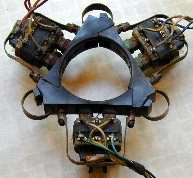
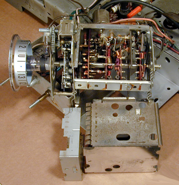
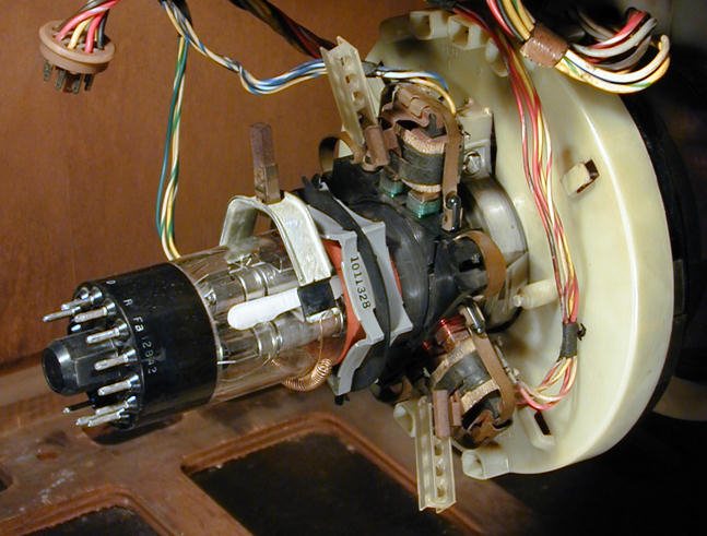
I had trouble identifying certain adjusters from the blurry little
photo in my photocopy of the schematic. Again, one of the experts solved
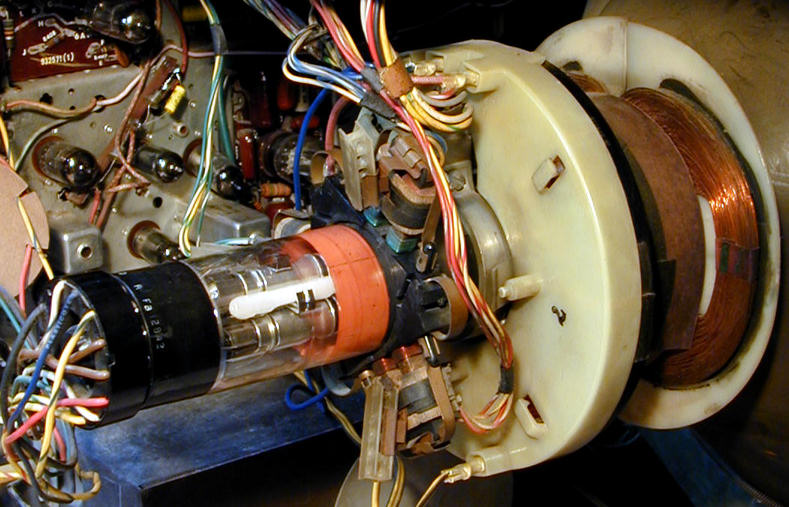
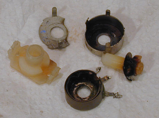
the mystery. Two parts were absent! Can you identify what's missing
from this picture?
The AWOL pieces are the purity rings and blue lateral magnet, normally mounted
on the picture tube neck behind the convergence assembly seen in the photo.
Although the TV picture was surprisingly normal, given their absence, you could never get
it right without those parts. Fortunately, I found another collector with
spares he was willing to donate.
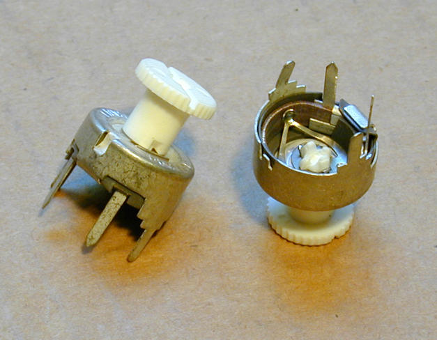
New Parts to the Rescue!
Here are the new parts, blue lateral magnet on the left, purity rings
on the right.

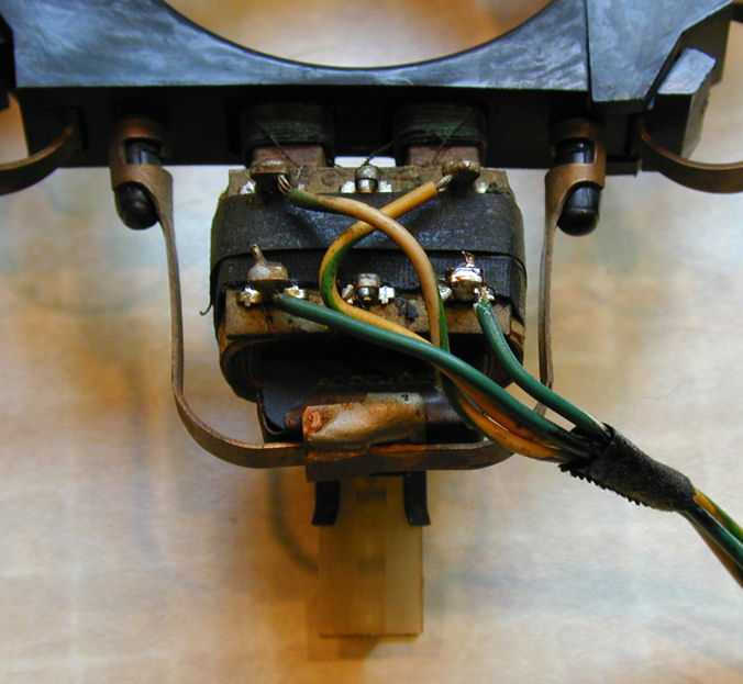
The next photo shows the parts installed on the picture tube neck.
The purity rings are slid on immediately behind the convergence
assembly (the gizmo with coils and wires, seen in a previous photo).
Farthest back on the neck is the blue lateral magnet, which is
held on with a spring.

Let's note three other things in the previous photo. First, the big ivory plastic
doughnut is the TV's main yoke, which focuses the electron beams on the front
of the picture tube. We'll be sliding that out and in during
the purity adjustment.
Directly behind the yoke, the convergence assembly has three sets of coils, two of which
are visible here. RCA used colored wire on the coils
and connecting wires for identification. The assembly
for the red electron gun has red wires, and so on.
Finally, note that each coil has a little plastic stick, held in a
metal clip and protruding back at a slight angle. (The rectangular stick
has a series of holes in it). These sticks hold magnets that can make
fine changes in the position of each color's electron beam. I would
become very familiar with these little sticks later on!
Before making color adjustments, you normally check and adjust all
"black and white" settings, such as focus and vertical linearity.
In trying to set vertical height and linearity, I discovered that the
vertical centering control on the back of the chassis was defective. It
had only one usable position: turning it at all collapsed
the entire screen into a horizontal line.
I made a note to replace that control later, and adjusted the vertical
as best I could.
What Are Purity and Convergence?
Purity and convergence are two concepts not used in the black and
white TV world, which I was more familiar with at the time. Let's briefly define each one.
TV pictures, as you probably know, are made by lighting up tiny dots on the screen.
On a black and white TV, each dot can be black, white, or any shade of gray.
On a color TV, each dot can be one of three colors—red, green, and blue—
or any combination of the three. A black and white picture tube lights up dots with
a single electron gun, while a color picture tube uses three guns, one for each color.
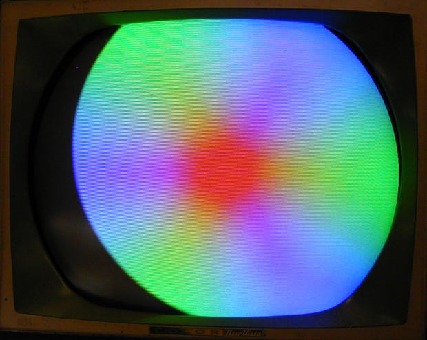
Purity is the ability of the TV to display a given color evenly across the
entire screen, without any blotches or variations. On a set with bad
purity, the screen will have blobby areas where colors are inaccurate, even
if the picture is otherwise sharp and clear.
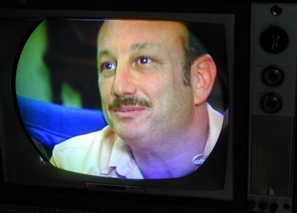
This pre-restoration photo shows an obvious purity defect. The flesh tones in
the man's face look fairly natural, but notice how they become too blue in the lower
right of the screen.
Convergence is the TV's ability to line up the electron beams from all three
guns so that they fall precisely on every dot on the screen. On a set with
bad convergence, images may be outlined or ghosted with wrong colors.
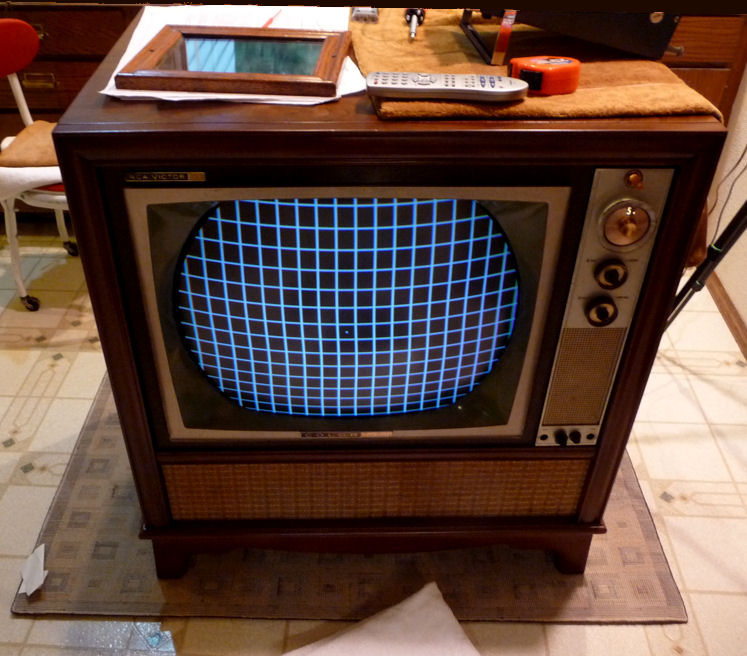
To adjust convergence, you need a TV pattern generator. Here is mine, a simple
model.

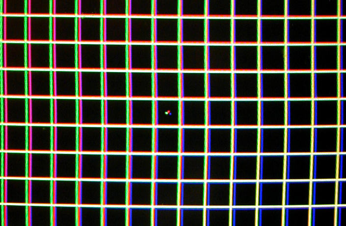
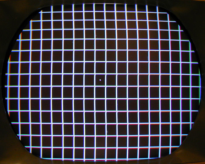
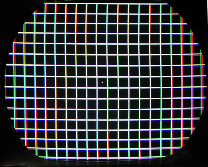
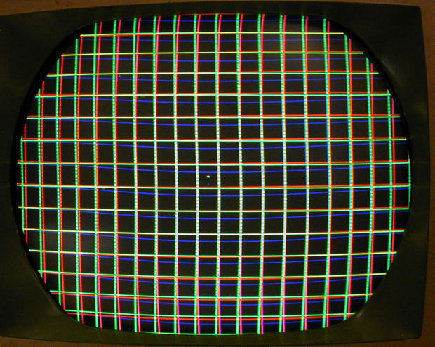
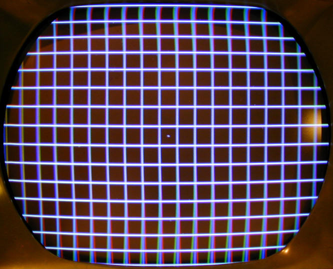
To check convergence, I set the generator to display a crosshatch pattern
with a single dot in the center. This photo shows poor convergence.
I have deliberately misadjusted the magnets to show the effect clearly.
Look at the three colored dots in the center and the mismatched color lines
throughout the screen. In a properly-converged TV, the three colored dots will align
to make a single white dot. The horizontal and vertical lines will likewise
be white.
Note how the horizontal mismatch becomes worse as you move
out from the center, and how the mismatch is different on left and right sides
of the screen. Every part of the image must be adjusted separately to
get correct convergence.
Purity Adjustment, Take One
Adjusting purity is simple in concept. You turn off the blue and green
electron guns, leaving only the red one active. Then you adjust the yoke and
purity rings until you have an even red color filling the entire
screen.
A terse description of the process will start with something like "kill
blue and green guns," to which I initially responded, "Say, what?"
I found a better description in the service manual, which tells you to
connect those guns to chassis ground through 100K resistors, using test
points shown in a diagram. That's what is happening here.

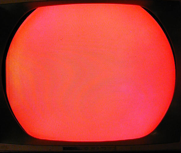
I set the pattern generator to display a
uniform blank screen. When all three
color guns are turned on, the screen is gray. When blue and green are
turned off, the screen is red.
When setting the purity, I had skipped the initial step in which you loosen the yoke,
slide it back, then slide it forward until you see an even, deep red color
on the entire screen. The purity rings may be adjusted as needed
at both stages to reduce impurities.
Here's what I saw with the blue and green guns turned off and the
yoke left in its original position. A big red ball.
(Ignore the moire effect in the photo, which is an artifact of my camera.)

I tried manipulating the purity rings, more to learn about them than
anything else, but didn't notice any great changes when viewing
the big red ball. The ring can be
adjusted in two ways: by rotating the entire assembly around the
picture tube neck, and by spreading the "ears" of the
magnetic collars closer or farther from each other.
The red color looked pretty even to me, so I decided to call the
purity good and move on to adjusting convergence.
Convergence Adjustment, Take One
As mentioned before, the three sticks on the convergence assembly
each hold a magnet. Sliding a stick in or out moves its
magnet closer to, or farther from, the corresponding electron gun.
For red and green, this moves the corresponding color
dot on a diagonal. For blue, it moves the dot up or down.
The sticks primarily affect the central screen area. For the edges, you need to
adjust another set of controls on a separate PC board.
Moving the sticks on the convergence assembly is called
static convergence. Adjusting the other controls is
dynamic convergence, and we'll get to that later.
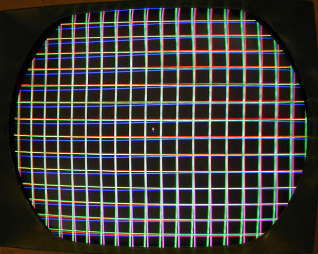
The next photo shows the crosshatch pattern after my first attempt
at adjusting convergence.

This is fairly decent convergence. The center dot is white, as are the lines
throughout most of the screen. Only the edges are off somewhat.
How does this affect an actual TV
picture? Below is an off-air photo that I took at this stage,
using a rabbit ear antenna and digital converter.
This picture is definitely better than the pre-restoration photo that showed
a man with a blue neck. Slight imperfections remain, of course.
James Spader's skin looks a tad purplish, but I hadn't bothered to tweak
the Tint control before taking this picture. The vertical height and linearity
are still a bit off, but I hadn't messed with them since finding the bad
vertical centering control.
I was pretty content with my first foray into color adjustments.
The picture had improved, and—most
important of all—I hadn't made things worse!
Purity Adjustment, Take Two
Since I hadn't done the first purity adjustment by the book, I
decided to start over. I wanted to learn these procedures well
enough to do them confidently in future projects.
I began by sliding the blue lateral magnet and convergence assembly
way back on the CRT neck, then loosening the clamp on the
yoke and sliding it back as well. I also turned off the green
and blue guns (see above).
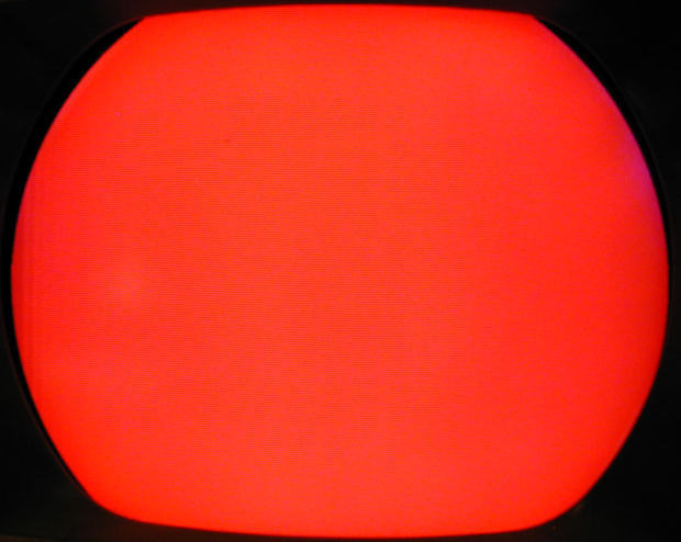
The instructions now tell you to start sliding the yoke forward until
you see a red ball in the middle, using the purity rings to make the
ball as round and deep red as you can. Here's what I saw.

It surprised me a bit that the entire lit portion of the screen was offset
on the CRT face. However, I was able to use the purity rings to get a nice
round red shape in the center, rather than a misshapen blob stretching
out in one direction or another.
As I slowly pushed the yoke forward, the image expanded and also re-centered
until red filled the screen.

Looking closely, I thought I could see a very slight crescent of magenta
discoloration in the extreme upper right, and an odd, faint wrinkle in
the left margin. Other than that, the screen looked great.
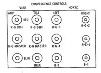
Convergence Adjustment, Take Two
Before setting purity, the manual had told me to set the controls on the
dynamic convergence board to the middles of their ranges, which I did.
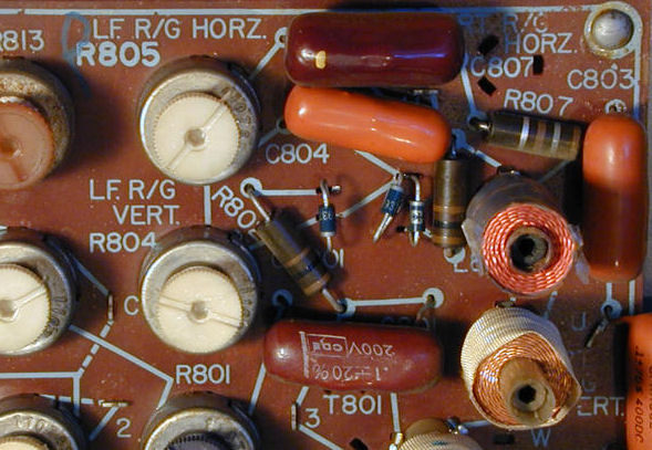
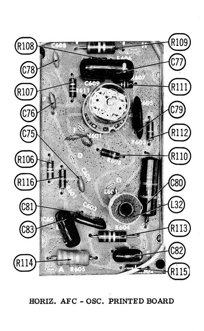
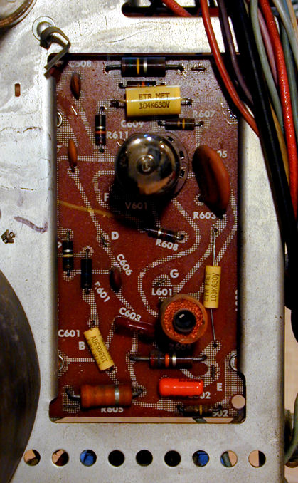
Here's the infamous board with a diagram identifying
its controls.


We'll return to this beast later, but notice that it has twelve controls:
nine potentiometers and three coils. Near the upper right is a component that puzzled
me at first. It's the gray item with a brown cylindrical core and four gray
stacked plates, much like a little selenium rectifier.
I learned that this is indeed a rectifier, with three diodes in one package.
The topmost plate was very loose—not a good sign. We'll return to that
guy, too.
Back to convergence. The instructions say to begin by adjusting the three
sticks with magnets until the three central color dots become a single white
dot. This was impossible, no matter how I slid the magnets in
and out. Here's the best that I could do at this stage.

Look at how the blue lines droop in the middle. Awful. Red and green wouldn't
converge to pure white, even in the very center. This was worse than the
"bad convergence" photo I had taken before changing anything
at all!
I decided to cheat and try adjusting controls on the dynamic convergence
board. This improved things somewhat, but the convergence was still
very poor.

I noted two things while adjusting controls. One of the pots was
almost impossible to turn. Worse, if I pushed a fingertip on the loose plate
of the little selenium rectifier, the blue lines jiggled all over the screen.
Time to power down and replace some parts. At the very least, I needed to
replace the vertical centering pot and that rectifier. It might be worth
checking all of the pots on that board, too.
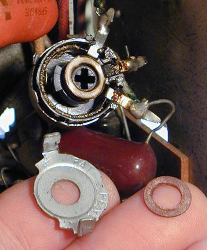
Vertical Centering Potentiometer
Before replacing the vertical centering potentiometer, I took it apart
and attempted a cleaning.

After cleaning and reassembly, the pot showed the same symptoms.
Meanwhile, a newsgroup member offered to mail me a replacement for
free, so I said, why not?
The replacement looked good on the outside, but completely failed
to register on my ohmmeter when tested. Here's why.

The innards were burned and melted—not salvageable. I went online
and ordered a new part. With the fresh pot in place, I was able to center
the screen and get acceptable vertical linearity.
Convergence Board Repairs
With improved linearity, I ran through convergence again and
realized just how dodgy some of the potentiometers were. One
was almost completely stuck, and two others were very stiff.
This prevented me from obtaining good horizontal
convergence of red and green vertical lines near the screen
edges.
New replacement potentiometers are not available nowadays, so
once again I put out a call to the faithful, and a fellow TV nut found
something in a parts stash that would fit.
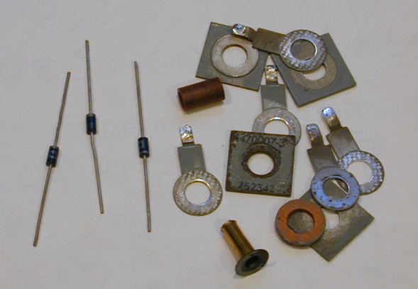
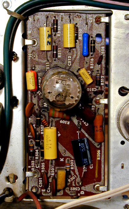
Meanwhile, I replaced the board's selenium rectifier with three
fast-response diodes. Again, here is the old rectifier still
on the board.
When I unsoldered the legs of the rectifier, the
whole thing just fell into pieces! The following photos show the new
diodes next to the old parts, and the new parts installed on the board.


With new diodes in place, what could be more fun than to re-converge the
television?
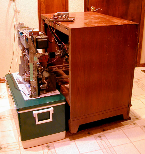
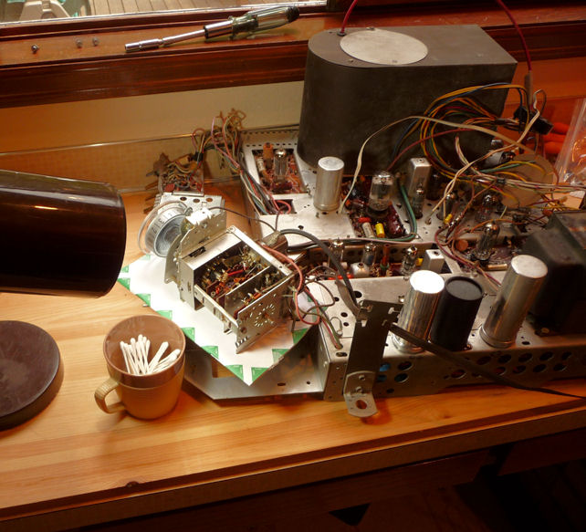
Adjusting High Voltage
But first, I reread the manual's setup instructions and noted the section about
adjusting high voltage output. I had avoided this earlier because the high
voltage adjuster is under the chassis and I had no extension cables to power up
the TV outside its cabinet.
Another collector pointed out that, with
care, I could set the chassis sideways behind the
cabinet and power up with the existing cables. Slapping a hand to
my forehead, I found an old ice chest the right size, and did
just that.
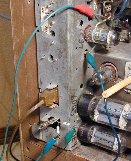
Testing high voltage involves disconnecting the HV lead
from the picture tube and connecting it to your HV probe,
which in turn is grounded to the chassis. For this I used
my trusty Sencore probe, seen on the bottom of this photo.

If you haven't messed with high voltage before, I advise caution. The black and
white TVs that I had previously worked on could generate a few thousand volts,
but a color television runs much higher—in this case, over
twenty thousand volts.
After insulating and taping the connections from the picture tube
cable to my probe, I measured exactly 20 KV, which is high enough to run
the set, but the schematic specified 21.8, so I adjusted it to that.
Convergence, Take Three
Actually, I had played with convergence more than three times by
now, but let's call this number three. I did the
full-dress procedure, starting with the twiddle sticks on
the convergence assembly and very carefully following
the instructions.
One thing I had earlier skipped was the instruction to
redo the static convergence as needed during dynamic
convergence. I didn't skip it this time, and eventually
the three little colored dots in the center
formed a pure white dot—something I hadn't seen
since I originally disturbed things.
Now the crosshatch pattern produced nice white lines on
about 80% of the screen. Red and green vertical lines near
the edges still wouldn't converge, however.
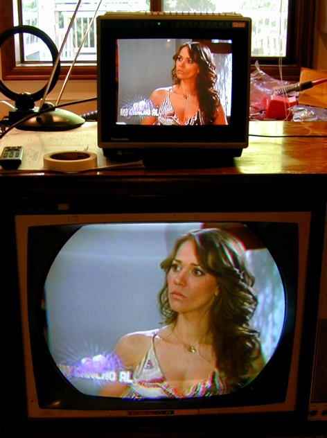
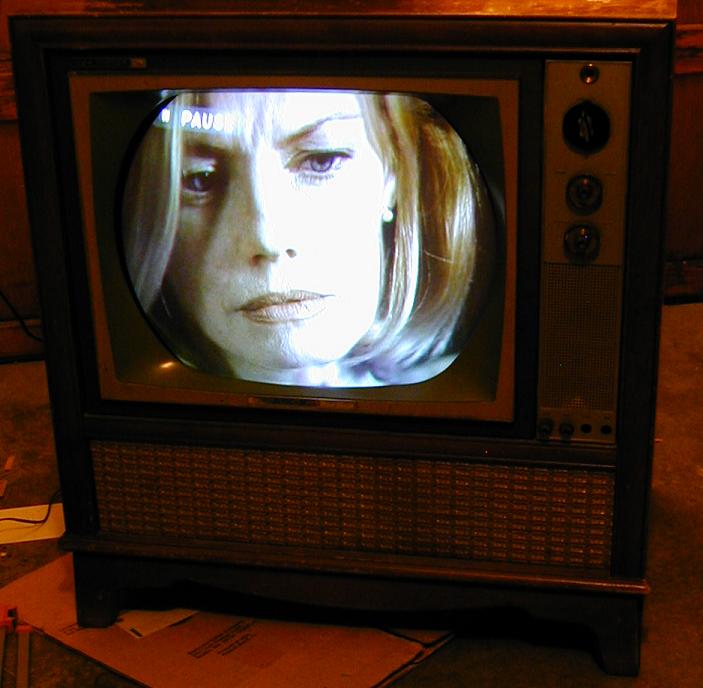
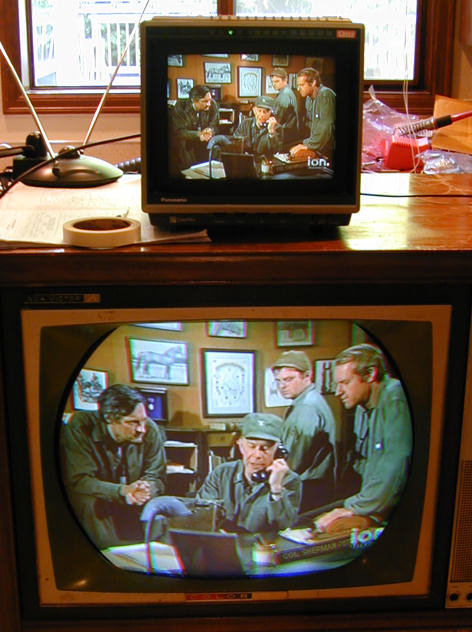
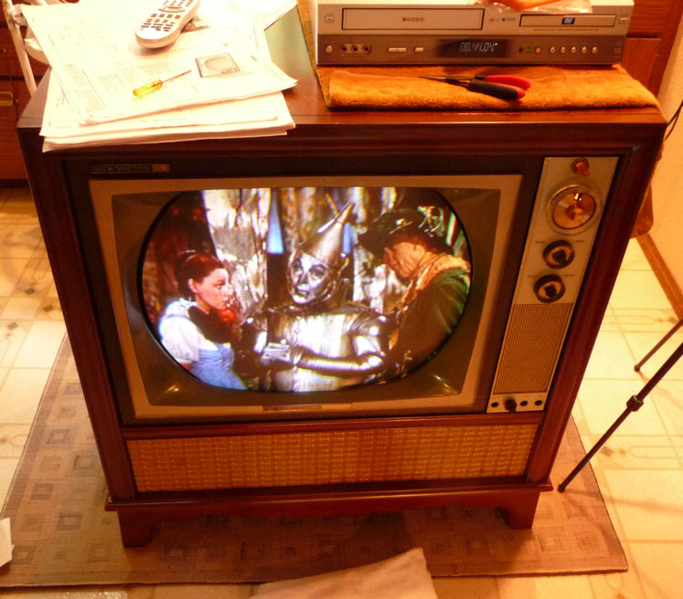
I took a couple of screen shots
using a rabbit ear antenna and digital converter, with a
modern solid-state TV on top of the RCA for comparison.
Let's look.

The colors on the CTC-11 look pretty true,
including flesh tones, which are hard to render.
The first photo shows some
red/green misconvergence. Note the color fringing on the upper
right edge of the woman's hair and the more obvious red/green
defects in her costume at the bottom.
The world of the M.A.S.H. guys is drabber, so an average
viewer wouldn't see much to complain about, except
slight fringing in the "ion" logo at lower right.
Convergence, Take Four
Meanwhile, I had gotten a couple of new potentiometers in the mail.
Here's a view of these cheap little critters.

I replaced the worst potentiometer on the board, but still
gained no improvement after yet another full adjustment. Notice how red and green
lines are bowed out at the top and bottom of the screen.

All of the capacitors on the convergence board were original,
and although "orange drop" (dipped mylar) caps tend
to be reliable, these were over forty years old.
I replaced those caps and, while I was at it, the four 100-ohm
resistors as well.
The new pot is the white one at the upper left in this view. The
new caps are mostly little yellow guys. Three of the capacitors
had oddball values, such as .082 mfd, which I produced by piggybacking
a pair of caps in parallel.
Referring again to the diagram, the pot that I replaced
is the Vertical R-G Difference Amp. The two
pots that should solve my red/green convergence problem
are in the middle row: the Vertical R-G Master Amp and the
Vertical R-G Master Tilt.
Rats. After installing 13 new components on the board, the problem persisted.
Would the Real Convergence Board Please Stand Up?
While working on the board, I had noticed a couple of components not shown
on the schematic. At far upper left in the previous photo, you can see the
top of a cylindrical metal can rectifier, next to a 270-ohm resistor. A friend
in a TV forum told me that these were used in models CTC-15 and higher, and
are not present in the CTC-11.
In short, my convergence board and assembly belong to a different, later model.
This does not sound good.
The two additional components lead to one of the board's R-G
controls, so it's not inconceivable that they might affect R-G convergence.
Comparing the CTC-11 and CTC-15 schematics, it appeared that these were
the only differences, apart from a different value in one of the pots.
Crossing my fingers, I temporarily disconnected the CTC-15-specific
components and installed a jumper.
Foiled again! Still no improvement.
Repairing a Broken Wire
When I mentioned the mismatched board and assembly in another forum,
one of the members half-jokingly suggested reversing connections to the
Red and Green coils on the assembly, to see what happened.
I wasn't desperate enough to start rewiring coils, but I did stick my
head into the cabinet to see how tricky that might be. (Answer: pretty
tricky.)
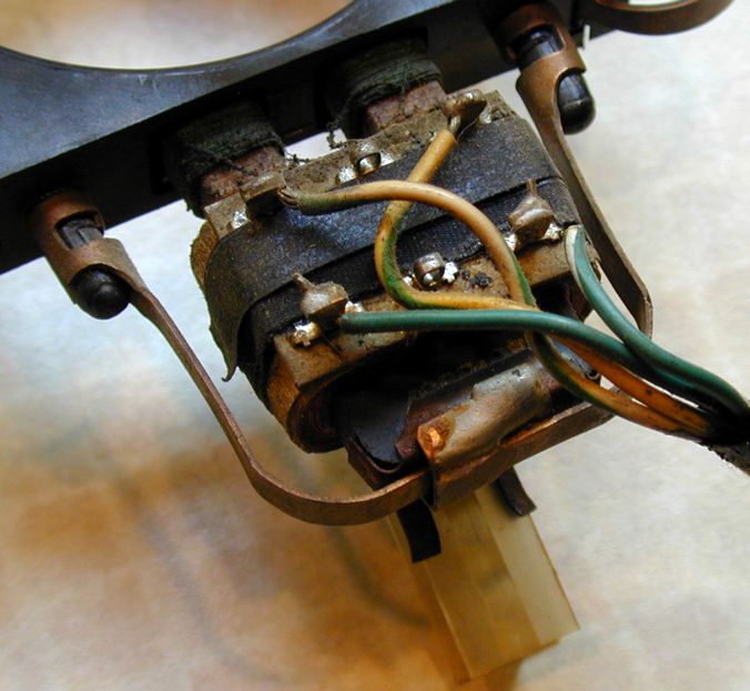
Looking closely at the Green coil, I spied something new. A wire had broken off
its terminal. Since the wire end was hanging very close to the terminal,
this wasn't obvious to the casual eye.
After I repaired that wire (it's the white-green lead), it was not
hard to get improved convergence.


Yes, convergence really does work better when all the wires between the board
and the coils are connected!
Declaring Victory
Television oldtimers have told me that convergence in these sets always
involved compromise. The controls are interactive, so a tiny
change for the better in one area may nudge things slightly off in
another. At some point you need to quit monkeying around and pick
the picture you like best, understanding that it'll never be perfect.
I did four more go-rounds at convergence and finally declared victory.
Now this a TV that I can enjoy
watching. The first of these images is a still photo. The second
is a link to a brief video clip. (Please excuse the tinny audio; the
microphone in my digital camera is the size of a pinhead.)

Cosmetic Restoration
As found, this television had an incorrect channel selector knob. It also was
missing the fine tuning knob. I got replacements from a fellow
collector. The tuning knob looks close, but I'm not sure it's an exact match for
this cabinet. The fine tuning knob isn't
quite correct, either; it's a hair too thick for the opening, and tends to bind.
I have the right number of small knobs, but two of them are too dark for
the cabinet, more black than medium brown.
Drop me a line if you happen to have any of
these items in your junkbox.
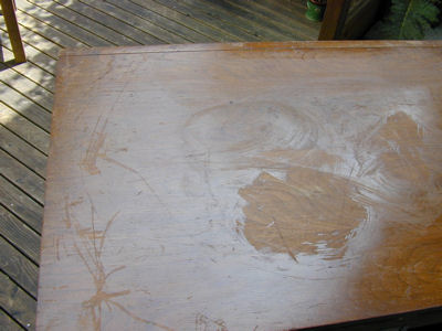
The cabinet needed more than light touchups. The finish was
badly faded from exposure to sunlight. The original color is a medium
dark brown, but the side panels have faded to a sickly greenish yellow
in some areas. The top also had deep gouges from dragging
heavy equipment across it.


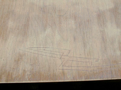
I avoid sanding when possible, but the gouges left no choice. Here is the
top after I sanded it and wetted it with mineral spirits to get an idea what
the grain would look like.

I used a rubber sanding block to make sure the old finish was removed evenly,
starting with 220 grade and going to 320 and 400 grade paper. This
cabinet should be attractive when I'm done.
The rest of the cabinet required no sanding, but the discolored finish
needed stripping. There also was a dent in the metal speaker grille, so I
decided to remove everything from the cabinet, rather than try to work
around the CRT, control panel and speaker grille
Removing Bezel and Control Panel
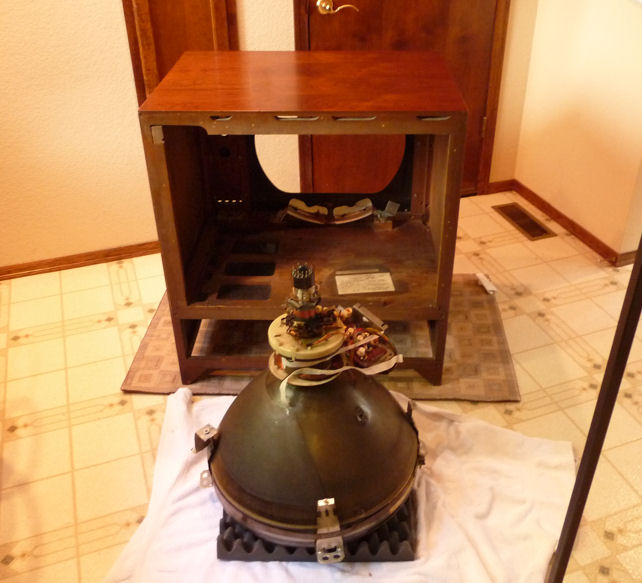
The first step is to remove the picture tube. Be careful—it's heavy!
This is best done with a helper.
I left the convergence board, yoke, blue lateral
magnet, and purity rings attached to the picture tube. Removing these
would force me to readjust the purity and convergence from scratch
after reinstallation. This way, perhaps I can get by with a minor tweak
to the convergence. The convergence board must be unscrewed from
the cabinet, of course. I temporarily taped it to the convergence
yoke and CRT neck.
Moving a big picture tube involves a risk of implosion. I wore safety
goggles, gloves, a thick jacket, and a scarf around my neck.
Catching a shard of flying glass in your eye or jugular vein can
really spoil your day!
The CRT is held in place by four metal straps fastened with sheet metal
screws. Loosen the bottom ones first. Be ready to catch the tube after loosening
the second screw on top. Grasp the freed-up tube by the bell, avoiding
stress on the fragile neck. Laying a towel or piece of cardboard inside the
cabinet, will give the tube something to slide on as you carefully bring it out.
The control panel is removed by loosening eight
sheet metal fasteners on the inside. The fasteners will slip off after
turning them partway; you don't need to completely unscrew them. Be careful not
to break the panel's plastic mounting posts. You also need
to remove a horizontal strip of wood from the upper inside of the cabinet.
The bezel around the picture tube comes off after
you remove several screws from the inside. The speaker board detaches
complete with speakers and grille cloth. After removing the bezel and
panel, I put the mounting screws back in their original holes so they wouldn't
get lost or mixed up.
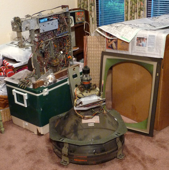
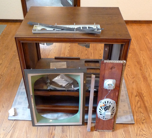
I stashed the CTC-11 parts in a spare room while
waiting for the cabinet to be finished. Looks like a pile of junk, but
I really will make it back into a television some day, I promise!
Stripping the Cabinet
I stripped the cabinet one side at a time, using a gel-type stripper.
After the stripper did its work, I removed it by scraping with an old putty
knife and mopping with wet paper towels. When the cabinet was dry, I went back
over that side with paper towels and lacquer thinner. Finally, I gave it a
very light sanding to match its color and smoothness to the top.
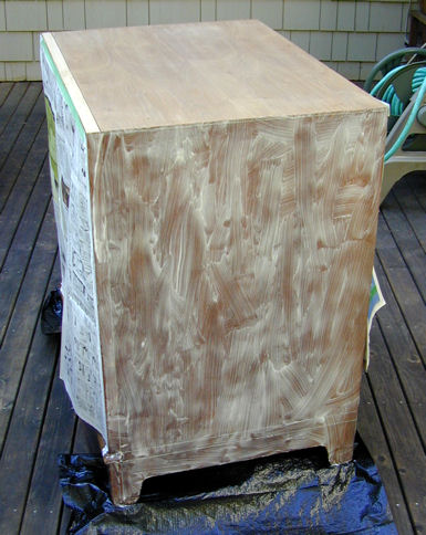
Rinse, repeat. You get the idea. Here is the cabinet after a sanding session,
trundled inside to escape a sudden rain. Earlier in this project, I had built
a sturdy rubber-wheeled dolly specifically to fit this set. It has been
a lifesaver.
That's as far as I had gotten by late October, 2009. The
cabinet was stripped and ready for new finish, but the weather turned
cold and rainy, not conducive to spraying lacquer outdoors. As winter
set in, I pondered what to do.
Two Slight Detours
While this project was underway, I stumbled across a second
CTC-11, priced at $1 in a local ad. Eager to learn more about color sets,
I picked it up and plunged into its restoration.
Soon after that, I ran across another bargain, a DuMont RA-103, and finished that
restoration, too. Read about those projects by clicking on the images below.

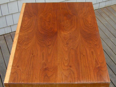
Time for a New Cabinet!
In February, 2010, I gave up on finishing the cabinet
myself and brought
it to Michael Mueller, a
Seattle furniture maker and refinisher. We agreed on a price and a couple
of weeks later, I had the cabinet back, looking sassy. What a contrast to
the battle-scarred hulk I had brought home months earlier.
Will I remember how to put all of these things together?

The speaker board, bezel, and control panel are back in place. Before reinstalling
them, I cleaned and polished all of the plastic and painted surfaces with
Novus Plastic Polish #2. Don't get too aggressive with the paint on the
control panel. It's rather delicate stuff.

Installing the Picture Tube and Chassis
Now to replace the picture tube. The yoke assemblies and convergence board
are still taped around the neck.

Before putting the tube back in, I donned a jacket and safety goggles. I
also put an old towel in the bottom of the chassis compartment.
Installing a heavy picture tube by yourself is not fun. I finally
got the job done, but it would have been easier with a helper. The
CRT mount on this TV is just plain cheesy. After you maneuver the tube
into its supporting front brackets, you secure it by screwing four bent
pieces of sheet metal to braces. In hindsight, I should have fashioned
some kind of temporary support to hold the tube in place while I fussed
with these sharp metal strips and screws.
Oops. While rassling the CRT into position, I managed to snap
a lead to the green convergence coil. Notice the loose green wire.

Slipping off the convergence yoke and resoldering the lead took only a few minutes,
but this escapade defeated the purpose of leaving that gear on the CRT neck in
the first place. Now I'll need to do
a full-dress reconvergence. Oh, well—it might have been unavoidable, anyway.
A couple of tasks remain before I can reinstall the chassis. When I restored this set, I
cleaned the tuner as I had done many radio bandswitches, by spraying DeOxit on the
contacts and working the tuner through all of the channels several times. When
restoring my second CTC-11, I found that
the quick spray-on method didn't quite cut it. I got better results
by dipping Q-tips in DeOxit and rubbing them on every contact surface, following
up the cleaner with an electronic lubricant.
These wafer-type tuners are known to be troublesome, so I cracked this one open
and took the time to clean it properly.

While I had the chassis on the bench, I also re-cleaned two controls that had
acted a little scratchy after their first cleaning: the volume control and
vertical hold.
Is It Really a TV?
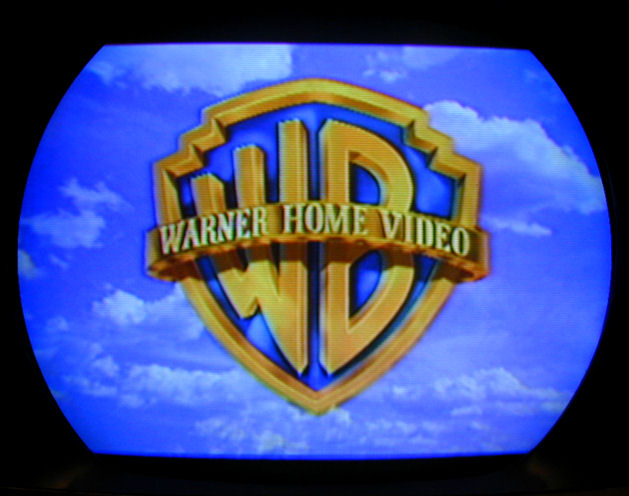
Enough fussing, already—let's fire this thing up!
Hmm, less than perfect. The first photo shows wild misconvergence, a split
screen, and a slight horizontal tilt. This is a monochrome scene from the
beginning of the Wizard of Oz, so the general absence of color isn't a problem.
As you can see from the image artifacts, the colors are all present, just
not in the right places!
I found the way back to Kansas before long. Initial corrections took only a few minutes
with the yoke, vertical controls, and convergence magnets. Since everything had been pulled off
the CRT neck, I spent about an hour redoing the purity, grayscale, and convergence.
(The "blue" crosshatch pattern is actually white; my camera makes most black and white
TV images too blue.)

Here's the TV in my workspace after tweaking. Not bad.

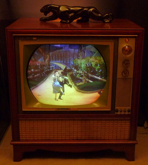
Kindly Degauss After Moving!
Now, to take an "after" photo, showing
the finished restoration in a less cluttered background. I moved the TV across the room
and turned it around for better lighting.
Arrgghhh! What happened here? The Scarecrow's cornfield is on fire,
Dorothy looks like she ate a green popsicle, and the Yellow Brick
Road is yellow, orange, and purple!


I had read that moving an early color TV can disturb the
colors, but I wondered whether the effect could be this drastic. A query to
the Videokarma.org color TV forum
quickly gave me the answer (Yes) and the advice to try degaussing.
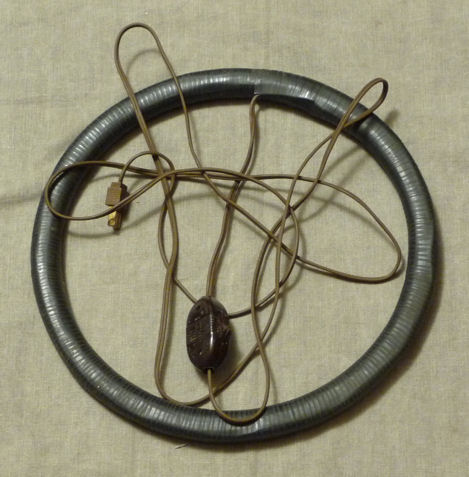
Degaussing coil to the rescue! I got this one from a retired oldtimer.

Degaussing fixed the problem in about one minute.
The procedure is simple. You stand about ten feet back from
the TV, then switch on the coil and advance, holding it in front
of you. When you reach the face of the picture tube, you slowly move the coil
around in circles for about 30 seconds. Then you slowly back away at
least six feet, place the coil flat on the floor, and switch it off.
Degaussing is necessary because the Earth has a magnetic field. The electron
beams in the picture tube are directed by magnetism in the yoke, convergence
magnets, purity rings, and convergence coils. In this case,
merely shifting the TV's orientation in Earth's magnetic field undid some of
my careful adjustments and sent the electrons astray.
Not long after this TV was built, manufacturers eliminated this problem
by including a built-in degaussing coil that energizes briefly each time
you switch on the set.
Degaussing can't hurt the picture tube. It's worth doing
before any setup procedure such as adjusting purity, as
well as after moving the TV. (Don't put an energized degaussing coil
behind a TV like this, which may demagnetize the convergence
magnets and purity rings.)
2011 Update
After using the TV occasionally for a couple of years, I noticed that
the vertical linearity had gone off, and I couldn't correct it with
the usual adjustments. The horizontal sync was also
getting a bit twitchy.
When I first restored this TV, I had replaced some small capacitors on
the audio board but I left all of the non-polarized originals on the sweep boards.
In the meantime, my restoration of a 1958
CTC-7 had shown me how
much the old "maroon drops" can degrade with age. They
may not have failed completely, but they had grown leaky enough to create
real problems.
Recapping the vertical and horizontal boards didn't take long, thanks
to my recent practice on the CTC-7 and a Philco
Miss America set.

Now, I could easily obtain correctly linearity and the horizontal was more
stable, too. After returning the set to my office, I degaussed the
picture tube and re-did the convergence for good measure. Recapping those boards
was so easy that I'm tempted to give my CTC-11H
the same treatment as a preventive.
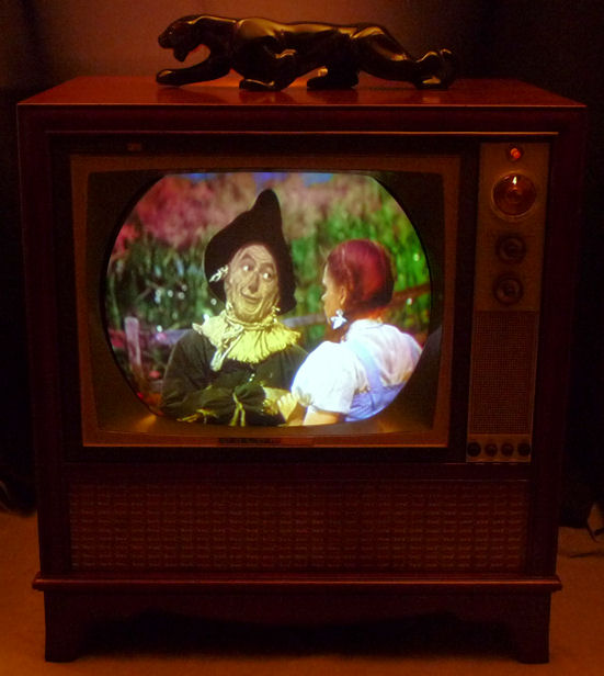
Final Thoughts
Here's a final photo showing my CTC-11 at its best. The initial restoration took more than a year,
with many time-outs and diversions, but I'm pleased with the result. This CTC-11 is a keeper!
Although setup procedures can be tedious, they're essential in every
color TV project. Merely replacing capacitors may give you a color picture,
but not one that's accurate and rich. I recommend the RCA Color TV
Pict-O-Guide, readily available in used markets. It explains the
theory behind purity, convergence, and so on, and describes every
procedure with plenty of color illustrations. The 1964 edition of this
book is just right for this model. The Sams service literature
also describes the procedures, but in more summary fashion.
I wouldn't recommend an early color TV as a beginner's project, but it can
be rewarding if you have some experience and a lot of patience.
Again, I'd like to thank all of the folks in TV forums who offered
generous advice. You know who you are!
Phil
|