Colonial Model 700 "New World" Globe Radio (1933)
Fashioned as a world globe, the Colonial "New World" model 700 is a
striking and unusual 1930s radio. It is also scarce,
making it desirable for collectors who like quirky cabinets.
I think it's cooler than the dickens, but the seller described it
as "ugly," one of Grandpa's old things that she was only too happy
to convert into cash.
Cabinet by Raymond Loewy
The Globe has a distinguished pedigree. Its cabinet was designed by none
other than Raymond Loewy,
fabled creator of designs for everything from locomotives to electric
shavers. Here is the original design patent drawing, dated June 24, 1933.
The drawing (in TIFF format) has been sized and saved at 300 DPI so that you can print it
for display next to your Globe, if you have one.
The drawing shows the overall design, but not the many details of the final
product. The patent declaration states that the opposite side of the
cabinet has the "same general appearance" as the one shown.

Description
In addition to natural Bakelite, the Globe was offered with black and ivory cases.
Regardless of color, it presents a very dramatic appearance.
Inside is a conventional 1930s AM receiver, using five tubes (25Z5, 6A7,
73, 78, and 43). A external antenna is a necessity. Since the Globe has
no RF amplifier, the longer the antenna, the better.
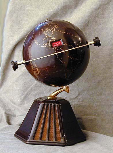
When you turn on the radio, the illuminated red dial is seen
through a small rectangular opening in the globe.
Circling the globe at its equator is a metal ring, plated in 22-karat gold.
At the top is a decorative brass finial showing the compass directions.
Large, wheel-shaped plated knobs control power, volume and tuning.
(When these photos were taken, my Globe
still had incorrect knobs. I have since found suitable reproductions.)
Regarding the model number, my Globe has a paper label identifying
it as a model 158, but I believe the usual American model number is 700, 701, or
702. Perhaps my set was built for the Canadian market, in which case model
numbers were often different.
In any case, the Riders service data
for model 700 matches the electronics of my radio. In addition to the schematic, it
gives important disassembly information and details of the unusual two-chassis design.
A Heartbreaking Shipping Experience
My Globe was in near-perfect condition when it left the seller's hands.
Sadly, it got broken during shipping across the United States.
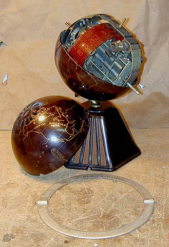
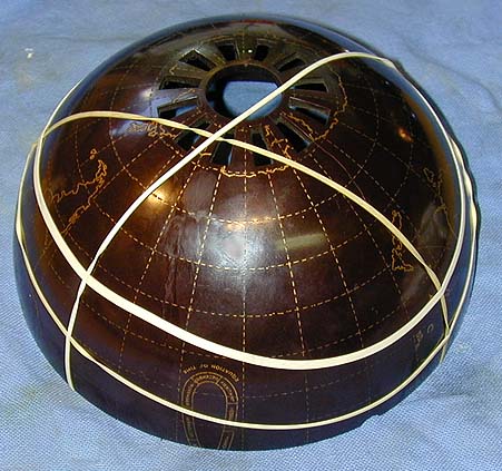
As the first photo shows, the lower hemisphere
suffered two large breaks.
The damage occurred because the chassis inside the globe, as well
as the upper hemisphere shell, were completely loose! During shipping, the
heavy chassis was free to pound up and down, splitting the lower hemisphere.
The shipping carton also lacked sufficient packing, so the entire radio was also
free to bounce up and down inside the box. In such circumstances,
one sharp knock is all it takes to break the case.
You can learn how to avoid such packing horrors on
this web page: How To Ship Old Radios Safely.
Apart from the breaks,
the cabinet is in wonderful condition. The gold-painted globe designs are
clear and unworn, contrasting brightly with the dark brown
Bakelite background.
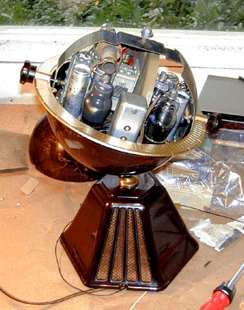
Inside the Globe
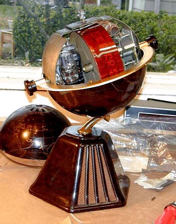
The next photo provides a view inside the Globe.
The metal equator ring has been removed in this view. It helps to secure the
chassis to the lower hemisphere. It also presents a shock hazard if it contacts
the shafts of the tuning and volume controls, which connect to the "hot" AC/DC
chassis. Fiber parts were originally used to insulate these metal parts
from the user. I used close-fitting plastic tubing on the control shafts to
insulate the ring.
The comparatively large tuning capacitor is visible in the right of the globe.
This radio did not use miniaturized components. Instead, it used two
separate chassis, dividing the electronics between the globe and the base.
The two chassis are connected by a multi-wire cable which runs through the
central metal support. The large, wheel-shaped knobs attach to shafts projecting at
opposite sides of the equator.
Disassembling the radio is quite a project.
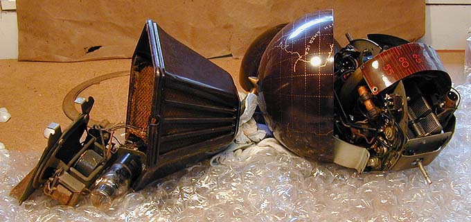
The next photo shows it partially disassembled. Notice how I carefully cushioned the parts
with some wadded bubble wrap and towels. On the workbench, you need to avoid scraping the
delicate paint on the globe case, as well as tearing out the thin wires which connect
the two chassis.

The lower chassis, seen on the left, contains the speaker and audio output tube.
The upper chassis contains the rest of the electronics.
To fully restore the electronics, and even to remove the broken lower
shell for gluing, I needed to unsolder all the connecting wires from the
lower chassis and draw them up through the hollow center support. Many of
these thin wires had lost insulation in spots, requiring their replacement.
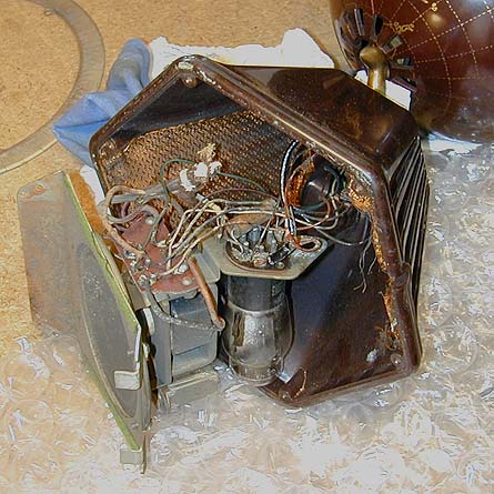
The next photo provides a closer view of the lower chassis.
The speaker and output tube are mounted on metal brackets that
screw into the Bakelite base. Sound from the speaker, as well as excess
heat, exits the base through opposing grille openings. The globe
portion of the case has discreet vents at the bottom and top
for ventilation. The cracks in my case started at the point where the base
of the lower hemisphere attach to the gooseneck, forming a weak spot.

Although dividing the electronics made this radio hard to service,
this scheme had several advantages. Putting the speaker
in the base avoided the need to cut a large, unsightly grille
opening in the globe. Dividing the components also reduced the
weight of the upper portion, so that the set would not be
too top-heavy. Putting the hot-running output
tube in the lower case also avoided concentrating too much heat
in the globe itself.
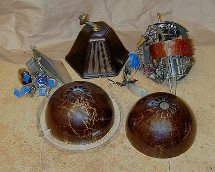
The next photo shows the radio disassembled. Before disconnecting the wires
between the two chassis, I labeled both ends of each wire with little blue tags.

Unwiring the lower chassis allowed me to draw the wire bundle through
the center support and finally separate the chassis from the cabinet.
In the previous photo, the lower chassis is on the left and the upper
chassis is on the right. Between them is the base portion of the cabinet.
Cosmetic Restoration
Fixing the big breaks in the lower shell took some nerve, but everything
turned out fine in the end.
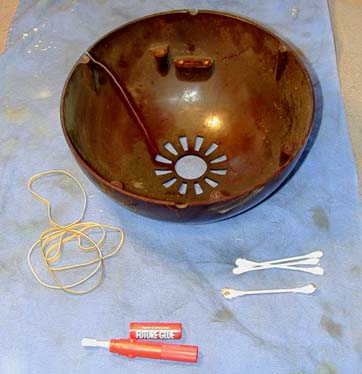
Before attempting any repairs, I carefully cleaned and polished the
globe exterior. Any work on these parts must be done with great care
to avoid rubbing off the gold paint. I used Q-tip swabs and
Novus plastic polish to clean between the painted
details and polish the background Bakelite. Then I gave the entire
outer surface a very gentle wipe with Novus polish, to give an even
shiny appearance and somewhat protect the painted detail.
That was the easy part! After consulting with some fellow restorers, I decided
that cyanoacrylate ("super glue") should work as well as anything to repair
the breaks. Fortunately, the breaks were clean, with no chipping visible
from the outside. I used a gel-type glue, which tends to help fill in any minute
spaces between the broken parts. I carefully cleaned the broken edges with alcohol, to remove
any trace of grease or dirt.

Before applying glue, I practiced
setting up the pieces and clamping them with rubber bands several times.
Once you have glued something with cyanoacrylate, it stays stuck, and I wanted
to minimize the possibility of gluing pieces off-kilter.
Taking a deep breath, I applied the glue, carefully pressed the pieces together,
and wrapped several rubber bands around the globe to hold everything in place.
After that glue had set, I ran an additional thin bead of glue behind the
cracks on the inside of the globe for additional reinforcement.

To my great relief, the repair worked! You can see a minute crack line in some
spots if you look very closely, but the average person would never notice that
the globe had been broken.
The gold plating on the equatorial ring is extremely thin, and worn away
on most Globes. The underside of my ring still looked great, so I carefully
sprayed the top with gold paint, followed by a clear coat to protect it.
Electronic Restoration
Now, if I could only get the radio working!
The first phase of the electronic work, as always, was to thoroughly clean the chassis and spray
DeOxit cleaner inside the controls. I also lubricated the tuning capacitor and replaced the
pilot lamp. This radio uses a 120-volt, 5-watt pilot lamp, in other words, an ordinary
night-light bulb.
Restuffing Paper Capacitors in the Original Shells
Since this is such a desirable radio, I decided to "restuff" the original
paper shells of the small capacitors rather than simply wire new ones
in their places.
This process takes a little time, but it's not difficult. The basic idea
is to heat the old paper capacitor to melt its wax, slide out the loosened innards,
and then insert a new capacitor.
To melt the wax, I put the old paper capacitors on a sheet of aluminum foil
and heated them in an oven at about 250 degrees for 20 minutes.
Then, working quickly, I put them on a heat resistant board and gently
slid out the capacitor innards. Wear gloves to protect your hands during
this operation. In some cases, you can draw the innards out by pulling on
one lead with a small pliers. In other cases, you need to push them out
using a screwdriver or other small implement.
Save any extra wax which comes out of the capacitors. You can use it to seal
the capacitor ends after installing the new unit.
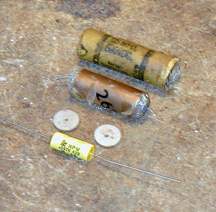
The next photo shows the disassembled paper capacitor. The cardboard shell is on top and
below it are the innards. Next are two round fiber pieces which sealed the end. (Not
all paper capacitors have these.) At the bottom is the new capacitor.

Before the cardboard shell cools, wipe it quickly with a paper towel to remove dirty
old wax. Then you can slip the new cap into the shell and seal it in place with
a hot glue gun. Fill the shell with glue, leaving a bit of empty space on each end.
To complete the authentic appearance, I then slipped the original
circular fiber pieces into each end
and sealed them by dripping a little of the original melted wax back over them.
After smoothing off the edges of the capacitor, you would never know that it's not original.
Some people also cut little circles of cardboard or paper to fit the ends. If you
can't salvage enough wax to seal the ends, melt a little hard beeswax, using a tan
wax crayon to color the wax as needed.
When all the paper capacitors had been restuffed, I installed them in the chassis.
Restuffing Electrolytic Capacitors in the Original Cans
I also hid replacement electrolytic capacitors inside the original
metal cans. One of the three original cans had been replaced with a newer cardboard-cased electrolytic,
so I found a dud can capacitor at a swap meet and used that one.
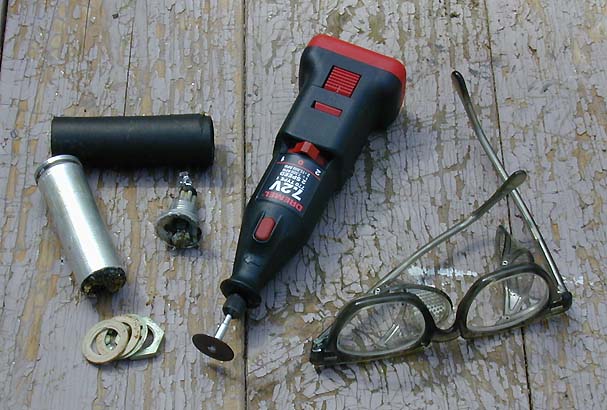
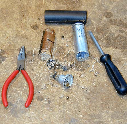
The next photo shows how I used a Dremel Moto-Tool with a cutting disc to cut away
the lower end of an original electrolytic can. (Don't forget the safety glasses!)

After cutting off the end, you can dig the innards out of the old can.

An even easier removal method is to screw a large wood screw into the
innards, then heat the entire can with a heat gun or hair dryer. When
the tarry adhesive has melted, you can pull out the innards with a pliers.
When the can is cleaned out, you can install a new electrolytic capacitor,
securing it as needed with hot glue or epoxy.
Some electrolytics use the can to make a connection to chassis ground, and others
do not, in which case the can is insulated from the chassis by a fiber washer.
Pay close attention to the connections in the original unit and
mark the new connections to indicate their polarity.
Electrolytic cans are usually made of aluminum, which can't be soldered. This requires
a little ingenuity, when the case forms the negative (ground) connection.
In this case, I mounted the positive lead of the new electrolytic on the inner end of the terminal
which leads out through the bottom. I drilled a tiny hole through one edge of the bottom cap
and ran the negative lead out there, where it could be clamped securely against the chassis
when the rebuilt unit is screwed back into place. Then I glued the bottom cap back in
place using JB Weld epoxy, and reinstalled it after the epoxy was dry.
Except for a thin gray epoxy stripe at the very bottom, the rebuilt electrolytic
can looks completely original.
You can read much more about recapping at Replacing
Capacitors in Old Radios.
Replacing a Resistance Line Cord with a Safer Substitute
The Globe is a transformerless "AC/DC" type radio. In AC/DC designs, the
filament draw from all the radio's tubes adds up to about 120 volts.
This eliminates the need for a heavy, expensive power transformer, making a lighter
and cheaper radio. It also permits you to run the radio from DC current, which
was not uncommon in the 1930s.
In the Globe, however, the tube filaments add up to only about 69 volts.
Some component must be placed between the 120-volt AC line and the filament string
to reduce the voltage by roughly 50 volts. Like many 1930s radios, the Globe used
a resistance line cord for this purpose.
Resistance line cords are not readily available nowadays. They also constitute a fire hazard,
being known as "curtain burners" in the old days.
There are three different ways to replace a resistance line cord: with a resistor, capacitor, or diode.
Resistor. First, you can simply
substitute a high-wattage resistor with the same value as the old resistance element.
The resistor has the disadvantage of generating extra heat if you put it inside the chassis.
The heat problem can be avoided by mounting the resistor
inside a little box at the end of the line cord, then using a three-wire cord to
run to the receiver. Your set then looks slightly less original, of course.
Capacitor. A second solution is to substitute an "AC-run" capacitor. These are
used for electric motors and can be purchased from a heating/air conditioning supplier.
Many restorers report success with this
solution, which has the advantage of generating virtually no heat. The capacitors
that I found were all quite large, however, about the size of a pack of
cigarettes. I rejected this solution because there wasn't enough
space to conveniently mount such a large component inside this unusual cabinet,
and I didn't want to run a three-wire cord from a box at the plug.
Diode. A third solution appeared in
a September, 2000 article in Antique
Radio Classified magazine. The author installed a modern silicon diode in place of
the resistance cord. The diode transmits current during only one part of the AC cycle,
cutting the input voltage to about 70%. Depending on your line current level, you
may need to add a small resistor in series with the diode, if the result is too high.
The diode creates no heat and it is also tiny, making installation a snap.
I mounted a type 1N4005 diode between terminals 17 and 18 on the lower terminal board.
(These numbers are from the Riders schematic.)
The banded end of the diode should face terminal 18, which supplies the filament string.
Remove the old resistance cord completely and install a new power cord
at terminals 17 and 14. For added safety, you can also install a 1.5-amp line fuse
between the AC plug and terminal 17.
Troubleshooting a Silent Radio
Another tedious chore was to replace the wires that connect the upper
and lower chassis through the gooseneck. The only original wire which I
retained was the shielded lead which carries the signal to the audio output tube.
I first soldered all the new leads to the terminal board on the upper chassis.
Then I tied the leads together into a thick cable, which I threaded through the gooseneck
into the lower cabinet. Finally, consulting my notes and the service sheets, I connected
the leads to the small terminal board on the lower chassis.
chassis.
With new capacitors, cables, and power supply, it was time to fire up the radio for testing.
Before doing so, I doublechecked all the connections between the two chassis.
Then, using an autotransformer, I slowly increased the line voltage.
Things looked good at first. The tube filaments gradually began to glow, but the radio was
completely silent, even I went above 80 or 90 volts, when you'd
expect to start hearing some sound.
With a silent radio, you normally start troubleshooting at the audio section and work
your way back through the radio's stages. The simplest check of the audio stage is
to briefly touch the tip of a soldering iron (with iron turned on) on one pole of the volume
control. If you hear a distinct buzz, your audio section is functional.
The radio failed this test, so I began to check individual components in the
audio output circuit. The tube had already been tested as good, so I ruled that out. The speaker
voice coil and audio output coil also had continuity, indicating that they were OK.
The speaker field coil appeared to be open, however.
This was grim news. Field coils are not easy to rewind, and it would be almost
impossible to find an exact replacement speaker for this radio. To make sure I had
identified the problem, I decided to temporarily wire in another speaker.
Replacing an Electrodynamic Speaker with a PM Speaker
Old radios can have two different types of speakers, electrodynamic or permanent-magnet (PM).
An electrodynamic speaker uses an electromagnet ("field coil") to create a stationary magnetic field
for the voice coil to operate in. A PM speaker uses a permanent magnet to create the stationary field.
The Globe uses an electrodynamic speaker. As in many 1930s radios, the speaker's field
coil serves two purposes. In addition to creating the stationary field, it acts as a choke
in the power supply circuit, helping the capacitors to filter out ripple from the AC current.
It is quite simple to replace an electrodynamic speaker with
a PM speaker. You wire the PM speaker in place of the old speaker.
Then you substitute a resistor of the right value for the original field coil.
(You can also substitute a choke of the appropriate value, if you have
space under the chassis.)
Since the resistor provides less filtering action than the original choke, you
usually need to increase the size of the filter capacitors, as well. Doubling the value of
the input, or first, filter capacitor may do the trick. Since this
replacement was just for test purposes, I left the filter capacitors alone for the
time being.
When my hotwiring was complete, I again powered up the radio. This time,
I could receive several local stations with reasonable fidelity.
Troubleshooting Buzz
It was too early to do a victory dance around the shop, however. The volume control
behaved very strangely. At the lowest and highest ends of the volume range, I could
hear a decent signal. Throughout the middle range, however, I heard nothing
but an awful buzz.
After doing some other checks, I isolated the problem as a bad volume control potentiometer.
I removed the pot, carefully opened its case, and cleaned its internals with DeOxit and
Q-tip swabs. Then I reassembled it for testing with an ohmmeter. More bad news! Evidently, the resistive
carbon had worn completely away throughout most of its travel. As a result, while the
pot showed normal resistance at both ends of the range, it was effectively open through
that part of the range employed in normal use.
As much as I hated to replace this great-looking old component, it was time for the
pot to go. After making some email appeals, I obtained a working pot with the right
value and not-too-dissimilar appearance (thanks, Marty!).
When I wired in the new volume control, the radio worked again . . . sort of. At the
highest volume, the radio sounded great. At the lowest end of its range, however,
there was yet another awful buzz!
The most common causes of loud hum are bad filter capacitors and a bad converter tube.
Since I had replaced the filter choke with a resistor, without increasing the value
of the filter capacitors, one might expect to hear some hum. Power supply hum, however,
is usually the same at all loudness levels, which didn't match my symptom.
Modulation hum did not appear to be the culprit, either. My repair books say that this
type of hum is present when you tune in a station, but it disappears when you tune in between
stations (i.e., at zero signal). This buzz is always present, no matter how you
move the tuner.
At this stage, I shipped the speaker to a professional restorer to have the field coil rewound,
putting other electronic work on hold.
When the speaker came back, it tested out perfectly. The work was done by Hank Brazeal,
whose email address is hankspkr@aol.com.
After installing the rebuilt speaker, I tested the power supply voltages, since the
speaker field coil is integral to the power supply filter. Both the B+ voltage
and the filament voltage were healthy, but the radio still exhibited peculiar behavior,
giving a loud buzz at low volumes and very weak reception at the highest volume.
To eliminate tubes as trouble sources, I replaced all of them with known-good tubes. My tube
testers can't handle these tube types, so substituting good tubes was the quickest way
to eliminate them from the equation.
Careful examination of the schematic and the volume control connections revealed
an oversight. The original volume control potentiometer's metal case had
been grounded to the chassis with a thick wire. My replacement pot was much
smaller and I wasn't comfortable with heating up its case enough to solder a ground
wire, so I initially forgot about the case ground connection. However, the schematic
indicated that the third, or "far" terminal of the volume
control should be grounded. When I connected a ground wire to this terminal,
the buzz disappeared.
Troubleshooting Weak Reception
So far, so good, but the reception was still very weak. The radio's AVC
voltages also looked bad. I measured around -.9 volts with no signal, and
only about -2 volts when tuning the radio to the strongest local station.
Normal AVC voltages are more like zero, or very slightly negative, volts
at no signal, and anywhere from -10 to -20 volts at the strongest signal.
I checked all the resistors associated with the AVC circuit, and replaced
three whose values had drifted beyond the specified values. I also performed
a quick alignment of the set, to find out if its IF would peak at all. This
radio uses 175 kHz for its IF frequency, considerably lower than most 1940s
and 1950s radios.
Alignment improved the radio's fidelity somewhat, but the reception was still
faint. To check the audio stage, I turned on my soldering iron and briefly
touched it to the center terminal of the volume control. The radio responded
with a loud buzz, indicating that the audio stage was basically functional.
In search of new ideas, I queried the rec.antiques.radio+phono
newsgroup, whose members suggested checking the antenna coil or trying a longer antenna.
Checking the antenna coil with an ohmmeter, I quickly found that it had continuity,
which ruled out the coil as a trouble source.
Up to this time, I had been using a 12-foot indoor antenna. Since this
radio has no RF amplification, it seemed possible that it simply needed a longer
antenna. I strung a temporary 100-foot antenna outside, and tried the radio
again. Reception was slightly stronger, but still far below what you'd normally expect.
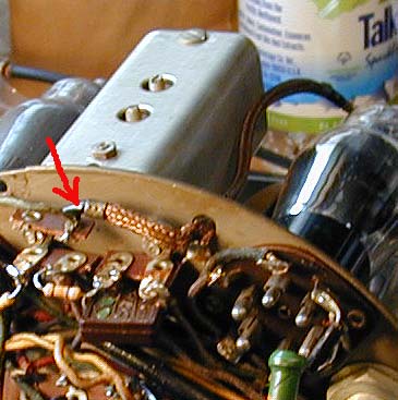
At this point, the radio's IF stage seemed like the most likely culprit.
I decided to remove the IF transformer can and
check the components inside. One of the can mounting nuts under the chassis
also holds in place a small terminal strip. One of the terminals on that strip
happens to connect to the lead for the 78 IF tube's grid. When I went to remove that nut,
I noticed that the terminal strip had been pushed out of place, just far enough
to short-circuit the 78 tube's grid lead against another nearby terminal.
Could it really be this easy? I nudged the terminal back into place and tightened
the nut. When I tried the radio
again, it burst into song!
In this photo, the arrow points to the grid lead after its terminal had
been pushed back up to eliminate the short circuit.

It's possible that the terminal was pushed out of place during shipping, when
the chassis was bouncing around loose inside the cabinet. I might also have
inadvertently nudged it when handling the chassis during earlier restoration.
In any case, I was delighted to solve the problem.
I did a final, more careful alignment, and then reassembled the radio. Here
are a couple of photos taken just prior to replacing the top shell.

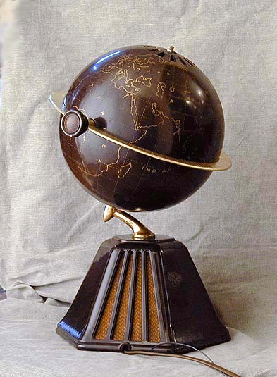
Final Thoughts
Here is the restored radio. Notice how the red dial shines through the opening in the
upper globe. Given all the subsequent political changes, the designers
were wise to label the continents, but not countries. The African continent,
for instance, is simply labeled Africa, and Europe is called Europe. It
might increase the historical appeal of this globe to have shown precise country
markings, but such precision painting would have driven the production cost
sky-high.
If you see the 1934 movie "Housewife,", starring Bette Davis, you can spot
a white Colonial Globe in her character's hotel room.
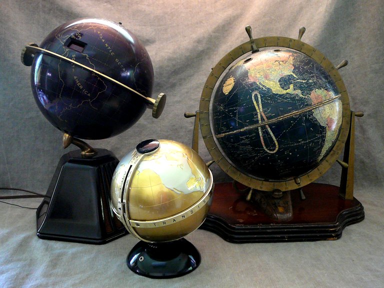
This was the first globe radio that I found. Here's the Colonial with my two other globe sets:
a 1940 Sonora Globe Navigator and a 1960s
transistor Vista NTR-66G:

I have seen another globe radio that is
styled like a classic black world globe, with chromed hardware.
No manufacturer name or other details were available in the photo that I saw.
This rare variant is obviously based on the Colonial
set, but its map has greater detail and multiple colors, and its dial scale
also has different colors and format.

I have seen a couple of these multicolored globes in photos, but not in
person. The owner of this one (Jon Fenwick, a UK collector) had no
clues about its origin. If anyone has more info about these oddball globes, please
send me an email.
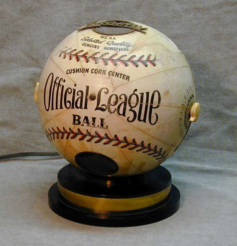
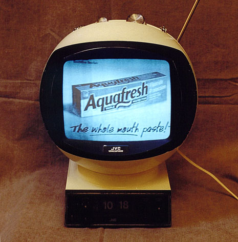
Other spherical sets in my collection include the Trophy baseball radio,
Weltron 2001 "space ball" radio, and JVC Videosphere television:


|