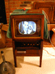
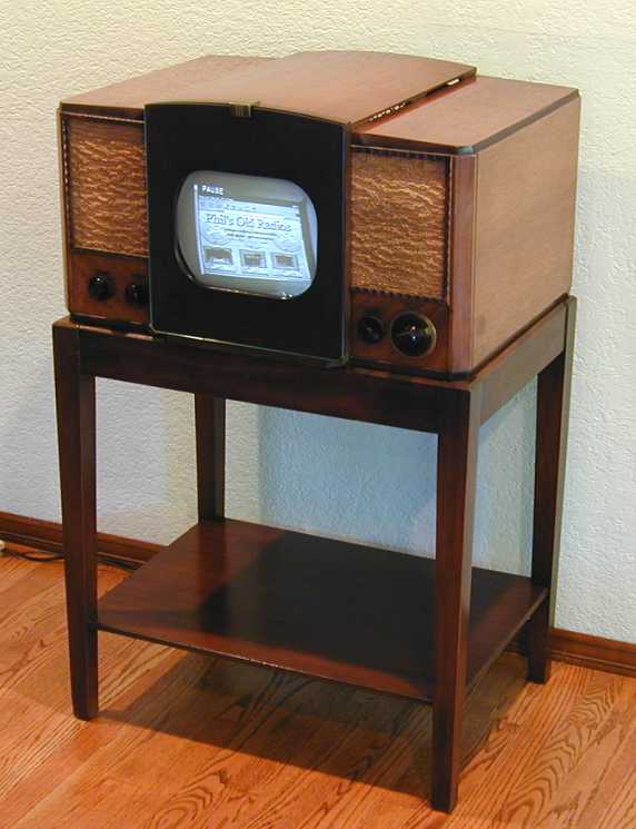
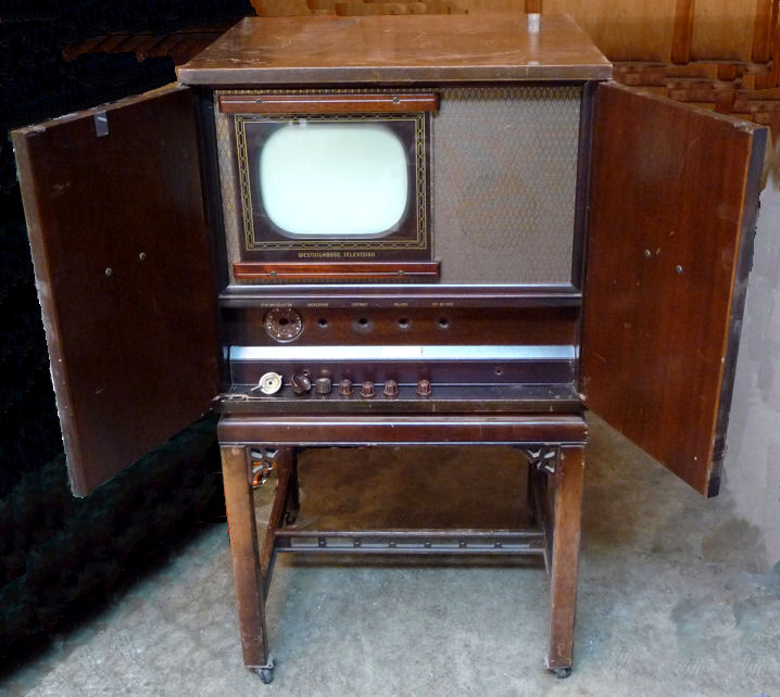
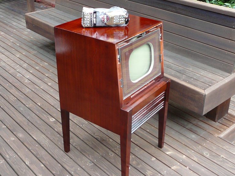
Philco Model 49-1240 Consolette Television (1949)

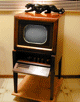
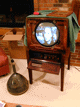


The Philco Model 49-1240 television, dubbed the "Consolette," might
be mistaken for a tabletop set on a stand, but it's all one piece,
a short console with narrow legs.
Description
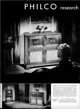
Philco started advertising its 1949 television models in late 1948. This two-page
spread from Life magazine appeared in November of that year. At first glance the left page
resembles previous Philco ads, featuring a glamorous woman in a dramatic
setting, listening to a large Philco radio/phonograph. The inset at the bottom of
the page pans over to show a different view of the room, however, with the same radio
and plant stand plus the new 1949 Philco Consolette.
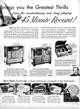
Philco advertised on TV and radio as well as in print. The ad reminds us
to watch
Philco Television Playhouse
every Sunday night, and the face
on the screen looks like Bing Crosby, who had a lucrative contract with Philco in those days.
Bing also hosted a weekly radio show,
Philco Radio Time, featured on the
right page of the ad.
The second two-page spread appeared in December, 1948, and urges you to "Make
This a Philco Christmas!"
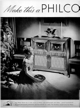
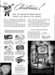
The main scene depicts the same dreamy blonde listening to a big radio/phono.
On the right page, the 1240 Consolette appears in a larger picture than before, using
the same inviting slogan, "When You're Ready for Television . . . ."
The "When You're Ready" slogan was a canny bit of marketing. Philco was
among the top-selling radio brands and the company understood that millions of
radio owners were eager to upgrade to TV, as soon as
affordable models were available and there was sufficient programming to
warrant the investment. By financing TV programs like Philco Television
Playhouse, big names like Philco and RCA helped to realize both goals.
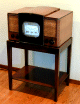
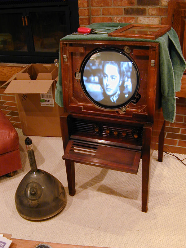
The 49-1240 Consolette is a bit unusual among 1940s TVs. Shorter than
most consoles, its thin legs resemble those on stands for tabletop sets
such as my RCA 630TS, shown in the
second photo.
A closer analog is seen in my
Westinghouse H-181, a
console with narrow legs. Sold by Westinghouse, it has a Philco 48-1001 chassis inside.

My Philco's label gives the tube layout, with 12LP4 inked in as the CRT type.
The model number is 49-1240, Code 123; the code number indicates minor electronic
differences.
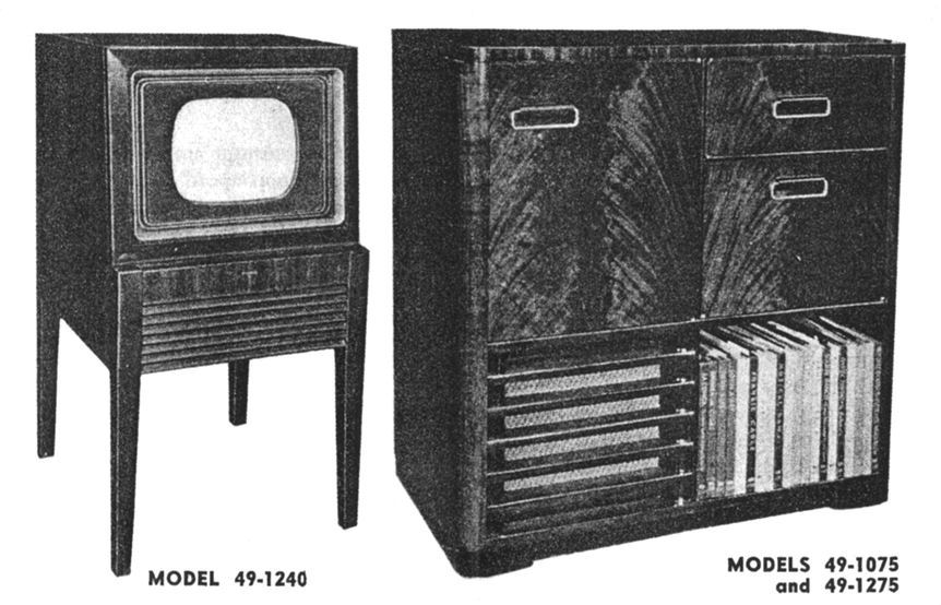
Philco used this chassis in a few 1949 televisions.
The 1240 was a TV-only consolette with 12-inch screen and the 1040 had a smaller
10-inch screen. Models 1075 and 1275 were "combos" in larger
cabinets including a TV, AM/FM radio, and record changer, with either 10-inch or 12-inch screens.
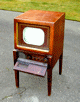
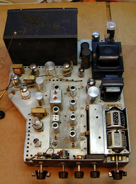
The first photo show models 49-1240 and 49-1x75; the second shows a 49-1040:


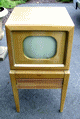
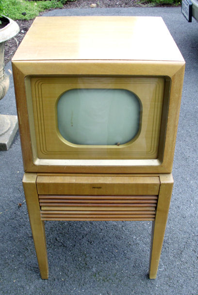
The veneered cabinets were available in two colors, mahogany or blonde.
A fellow collector sent me photos of her 49-1240 in a blonde cabinet. Notice
that the knobs for the blonde model are lighter in color (this set's Contrast knob is not original).
The 49-1240 has 26 tubes:
| Tube |
Type |
Function |
| V1 |
6AG5 |
RF Amplifier |
| V2 |
6AG5 |
Mixer |
| V3 |
6J6 |
Oscillator |
| V4 |
6AG5 |
1st Video IF Amplifier |
| V5 |
6AG5 |
2nd Video IF Amplifier |
| V6 |
6AG5 |
3rd Video IF Amplifier |
| V7 |
6AG5 |
4th Video IF Amplifier |
| V8 |
6AL5 |
Video detector / AGC Rectifier |
| V9 |
12AU7 |
Video Amplifier |
| V10 |
7F7 |
DC Restorer / 2nd Sync amp. |
| V11 |
6BA6 |
1st Audio IF Amplifier |
| V12 |
6AU6 |
2nd Audio IF Amplifier |
| V13 |
6AL5 |
Ratio Detector |
| V14 |
6AT6 |
Audio Amplifier |
| V15 |
6K6GT |
Audio Output |
| V16 |
7N7 |
1st Sync. Amp. / Sync. Sep. |
| V17 |
7N7 |
Vertical Oscillator |
| V18 |
6K6GT |
Vertical Output |
| V19 |
7N7 |
Horiz. Osc. / Horiz. AFC |
| V20 |
6BG6C |
Horizontal Output |
| V21 |
5V4G |
Horizontal Damping |
| V22 |
1B3GT |
High Voltage Rectifier |
| V23 |
1B3GT |
High Voltage Rectifier |
| V24 |
5U4G |
Low Voltage Rectifier |
| V25 |
7Z4 |
Low Voltage Rectifier |
| V26 |
12LP4 |
Picture Tube |
The 49-1240's electronics are pretty conventional, one exception
being the use of Loctal type tubes, which Philco favored for a few years.
With four stages of IF (intermediate frequency) amplification, AGC
(automatic gain control), and DC restoration, its performance was
competitive with better TVs of the day.
Since the 12LP4 CRT requires higher voltage than a 10-inch tube, the
TV has a voltage doubler, with two 1B3GT high-voltage rectifiers. It also uses a pair
of low-voltage rectifier tubes. A 5U4G rectifier supplies voltage for
the final video stages and the vertical and horizontal sweep sections;
a 7Z4 rectifier supplies the rest of the television.
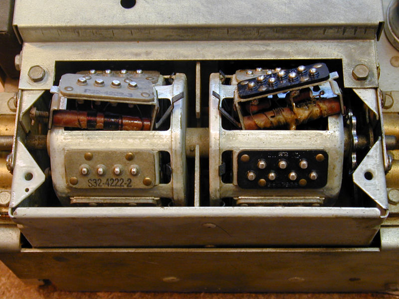
This TV has an eight-channel tuner. The tuning dial is labeled 1-2 (meaning either
Channel 1 or Channel 2), 3, 4, 5-6, 7, 8-9, 10-11, 12-13.
For technical reasons, the FCC limited the number of VHF stations
broadcasting in any given city to a maximum of eight. When you bought this TV, the Philco dealer would
set up the tuner to receive the stations available in your area.
Eight-channel tuners were fairly common amongst early TVs,
including my 1948 Motorola VT-73.
The following photo shows the turret-style tuner in action (click the thumbnail to
view the animated .GIF).
Each channel section contains two strips with raised contacts. Turning the tuner moves
that pair of strips into place against the stationary contacts, switching in the
coils for that channel. The stationary contacts are
spring-loaded, depressing slightly when the moving contacts touch them.
To configure the tuner for a new station, the dealer would simply pop out
one pair of strips and substitute strips for a different channel. In the
next photo, I have snapped out the strips for Channel 3.

The front strip holds the oscillator coil, whose screw slug is tunable through an opening
in the front panel, and the rear one holds the antenna and RF coils.
Service Documentation
If you're restoring a 49-1240, avoid the Sams manual. It covers nine
different models and its schematic doesn't match this television. I had
already started replacing capacitors before I recognized just how far off
the Sams docs are.
I then got copies of some Philco factory documentation from
fellow collector Cliff Benham: the
Television Group 1A manual and the
49-1240 Supplement. I used these
during most of the restoration.
When I ran into problems with the horizontal section, I eventually made the drive
to our regional library, where I photocopied the complete Riders documentation.
The correct docs are found in Riders TV Volumes 2 and 4. Much of the material is
identical for models 49-1075 and 49-1240, and it includes theory of
operation, oscilloscope waveform models, troubleshooting
suggestions, and 1240-specific details.
Finding the 49-1240
This television was advertised on the local Craigslist website. When I phoned to ask
about it, I was directed to a local E-waste recycling facility (!). There, in a huge
warehouse filled with bins of computer monitor CRTs and the like, stood this
forlorn little refugee from the 1940s. If nobody bought it, the owner assured me,
it would be chopped up for recycling.
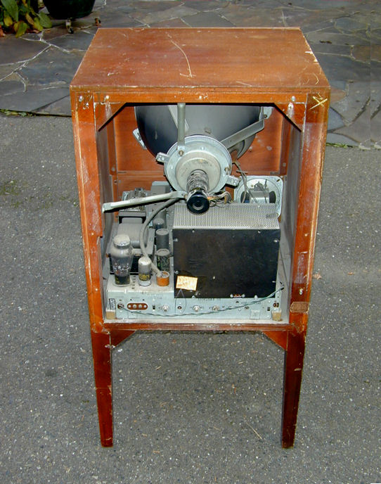
I gave it quick look to make sure it was complete and then took it home for $40.
The cabinet is rather beat up, but it's structurally sound.
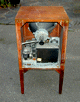
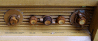
In the first photo, the hinged front cover has been swung down to reveal the knobs,
all of which are present. The TV also has its original back cover, which I had removed to show the chassis.
First Look
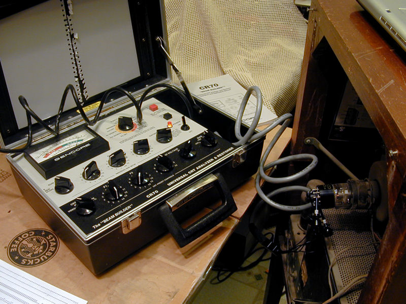
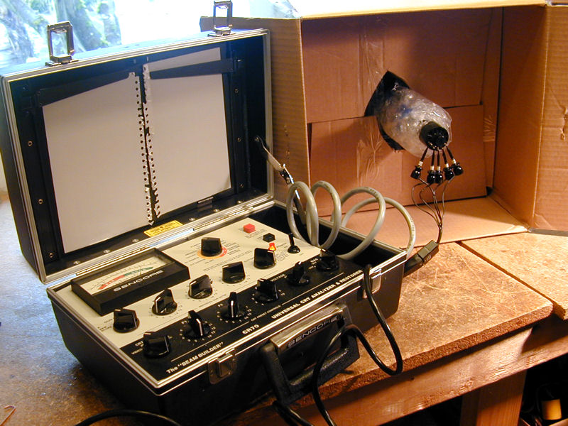
Moving into the workshop, my first priority was to test the 12LP4 picture tube.
If that were a dud, my $40 bargain TV would cost a lot more to get working. Fortunately,
it looked very strong on my Sencore CR70 tester. In this photo, you can see the
indicator needle resting well into the green Good zone.

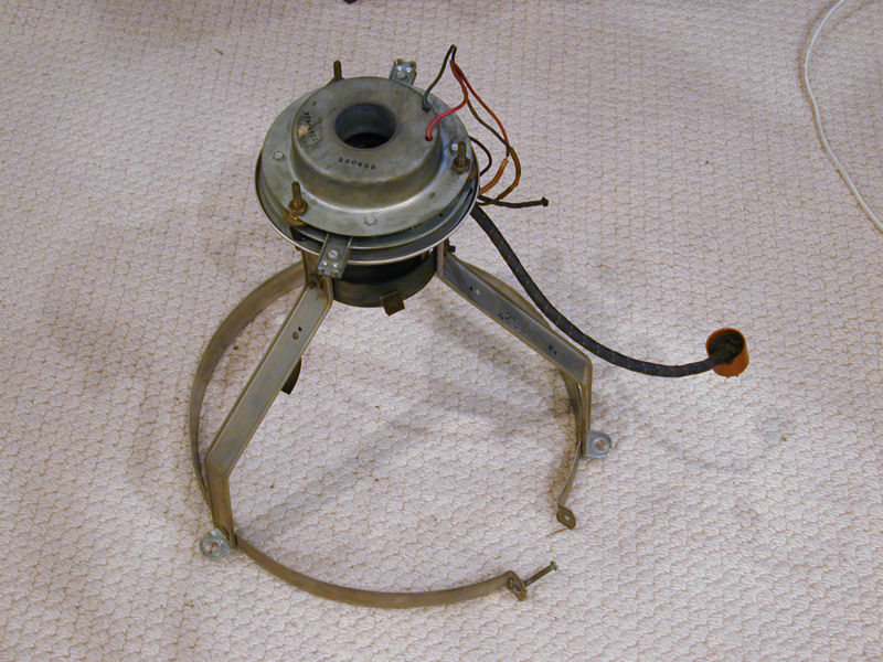
Looking inside, I see plenty of dry dust, but no rust.

The dust is easily brushed off.

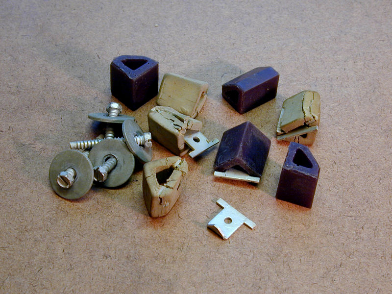
You can see four grey rubber bumpers amongst the mounting hardware.
These bumpers fit under the chassis corners to dampen vibrations (either from the
TV's speaker or the surrounding environment) that might cause unwanted oscillation.
The rubber frequently deteriorates with age, but you can buy replacements from
Renovated Radios.
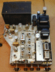
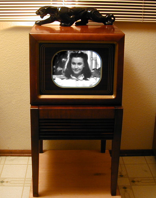
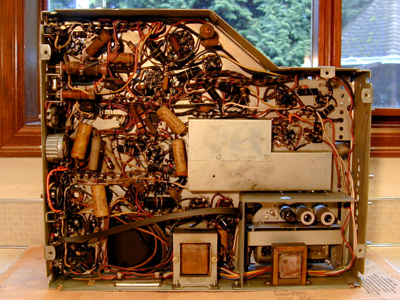
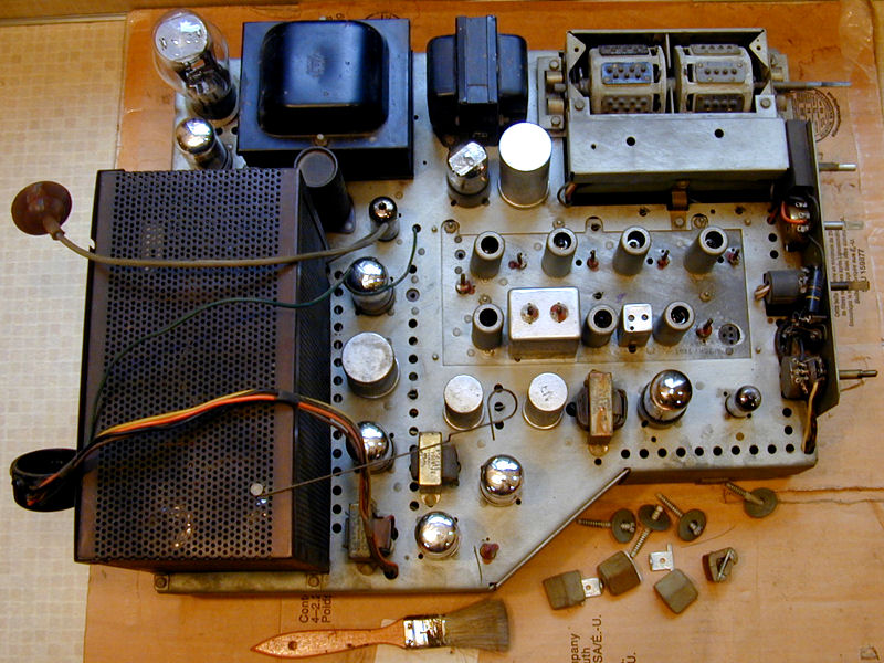
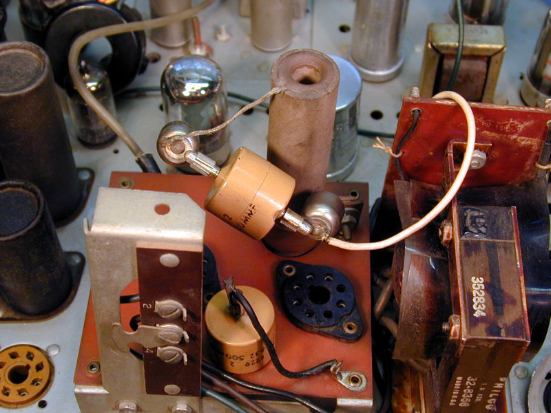
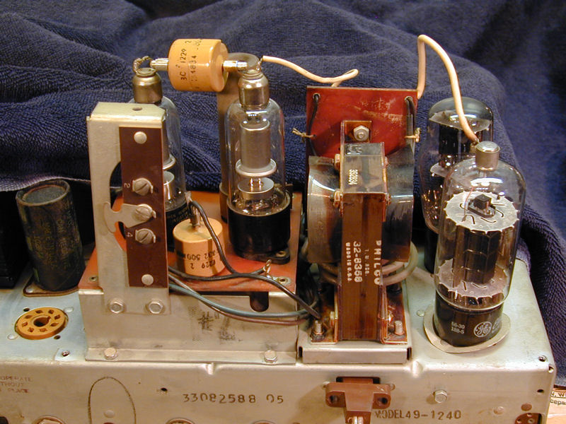
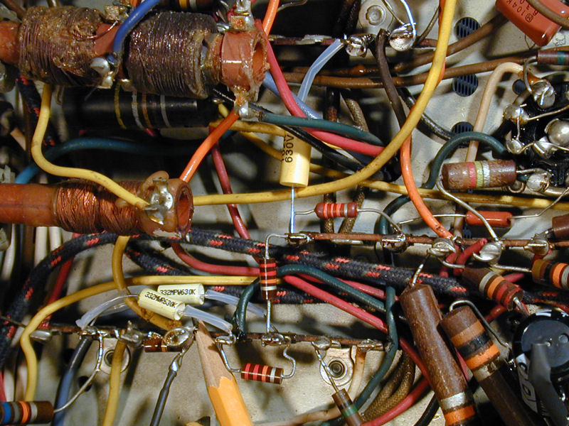
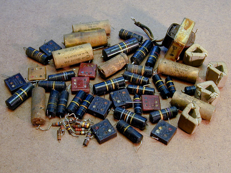
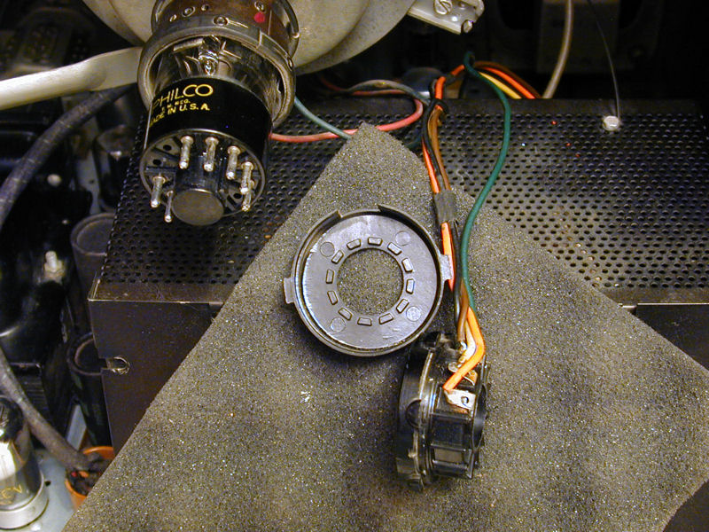
Turning the chassis on its side exposes the underbelly, crammed with paper
and plastic-coated "bumblebee" capacitors.
Three tubes are mounted upside down, near the tuner. These comprise the
"front end," the TV's RF amplifier, oscillator, and mixer.
One of them is missing a shield, but I have several spares lying around
(somewhere!).
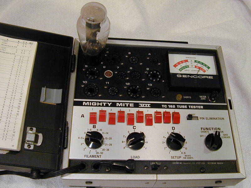
Cleaning and Testing
I begin every restoration with basic testing and cleanup. In this photo, I'm testing
the 5U4G rectifier tube, which looks fine. I haven't yet wiped
the dust off the tube; if it turned out to be a dud, that would be time wasted.

Once I know that the tube is good, I'll clean off the dust, and, much more importantly,
clean all of its pins. When returning each tube to
its socket, I plug and unplug it several times, in case the socket holes are
dirty or slightly corroded. (In rare cases where socket holes are seriously gunked
up, I clean them with liquid DeOxit D100L and a tiny stainless steel brush.)
It's equally important to clean the TV's switches and controls, such as volume and brightness.
This takes only a few minutes and it's better done sooner than later.
This TV has two back-panel switches that are
easy to overlook: an AGC switch that lets you switch off the automatic gain control system (useful
in some performance situations) and a Phono switch that powers down much of the
TV, used only in "combo" models that include a record changer.
I use DeOxit for most cleaning, letting the TV sit overnight to let
excess cleaner evaporate before I power it up again.
The turret tuner is simple to clean and lubricate. Resist the temptation
to scrub the tuner contacts with anything abrasive.
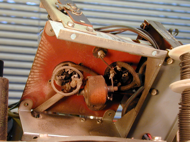
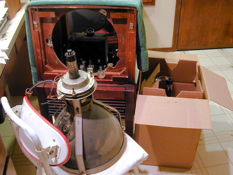
If you remove the high-voltage cage, you can then loosen and raise the platform seen below,
which holds the flyback transformer and two 1B3GT rectifier tubes. There's plenty of
dust underneath mine, some of it deposited in a pattern radiating out from
the rectifier socket.

High-voltage cage dust cleans up easily with isopropyl alcohol. You don't want dust in
this area because it attracts grime, which eventually may cause arcing.
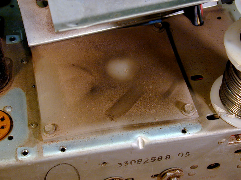
Underneath the platform is this insulating pad, also dirty.

Another reason to clean this area is to inspect for carbon trails or burned paths,
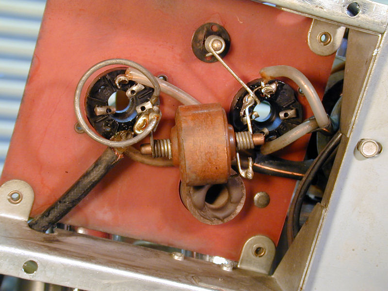
which would indicate there has been arcing in the past. The next photos show the results of cleaning.


In the third photo, you see the two high-voltage rectifier tubes on the left
and the damper and horizontal output tubes on the right.
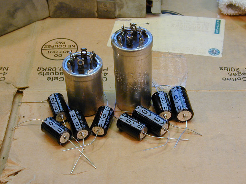
Replacing Capacitors
We're ready to begin
replacing capacitors, beginning with electrolytics in
the power supply.
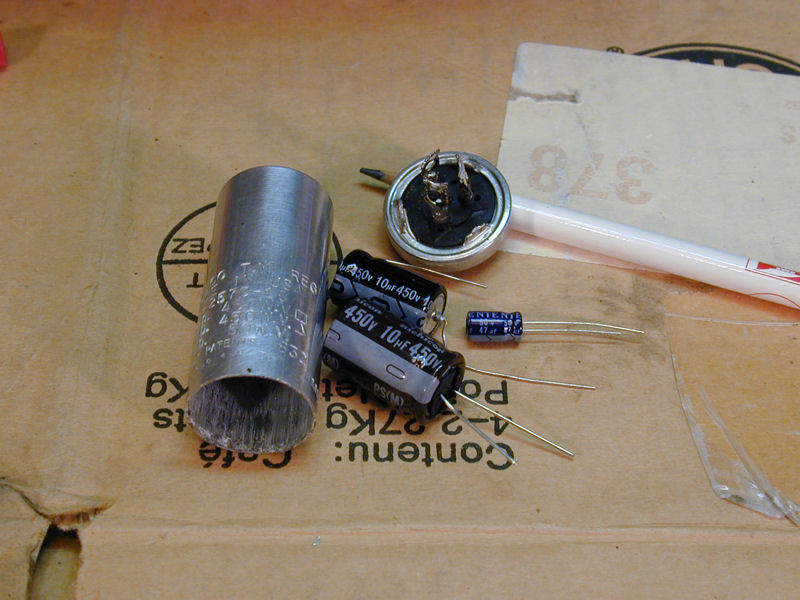
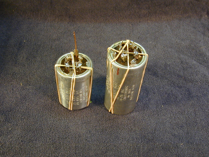
The can shown in the next photo originally held
three electrolytics and the new replacements will just fit. I sawed off the can's top, pulled out
the innards after melting the adhesive with a heat gun, and then drilled holes in the
base for the new capacitor leads to reach the original terminals.


Here are before and after photos, showing the place where that can attaches under
the chassis. To simplify reinstallation, I labeled the capacitor leads with little
tags.


The space was too cramped to easily unsolder the can's tabs and draw them up
through the chassis, so I had simply twisted them off to remove the can.
After it was restuffed with new caps, I glued the can back onto the chassis,
steadying it with tape.

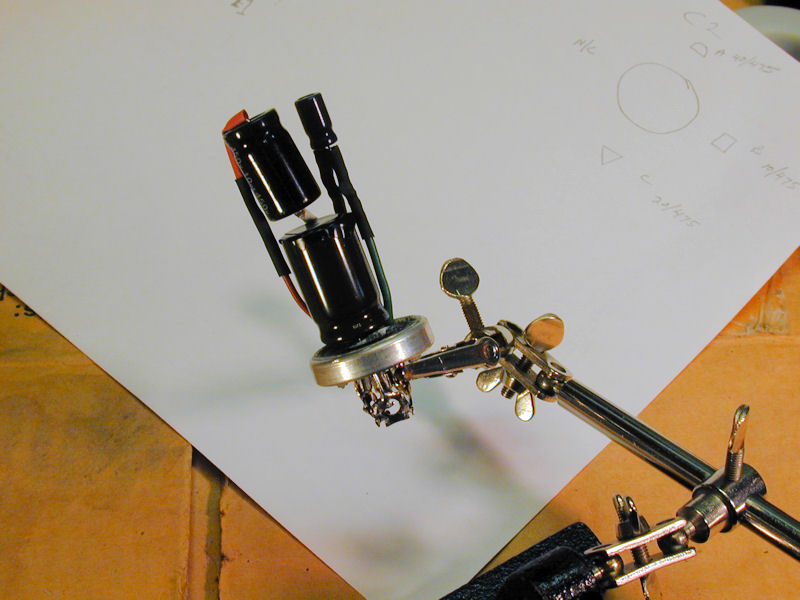
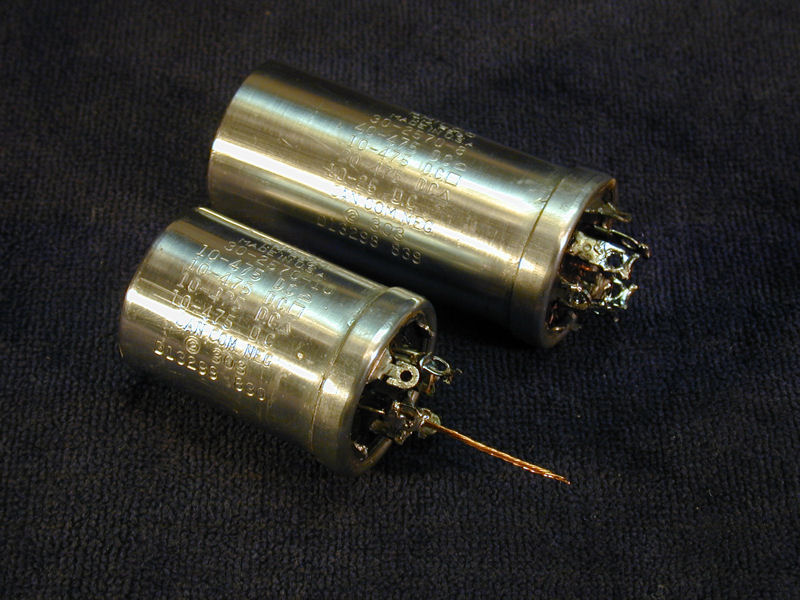
The next pair of cans won't be so easy. Each can holds four capacitors and the replacements
can't all fit inside.

I'll fit in as many as possible and install the rest under the chassis.
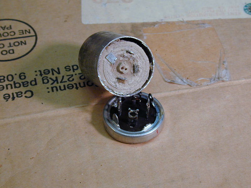
Incidentally, have you ever wondered why old electrolytics fail? Look at
this one—dried out and shrunken! Forget about trying to
"re-form" this capacitor and make it work again. It is garbage.

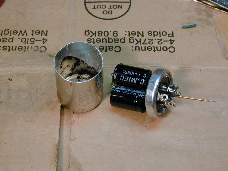
Eventually, both cans have been stuffed with new caps and reassembled. The long
copper lead on the short one is a new ground connection that will be shared
by a couple of caps outside the can.


In the second photo, I have glued the cans back onto the bases, using
rubber bands to hold the parts in place.
Eventually, all of the paper and electrolytic caps had been replaced. Time
to power up!
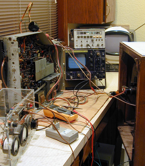
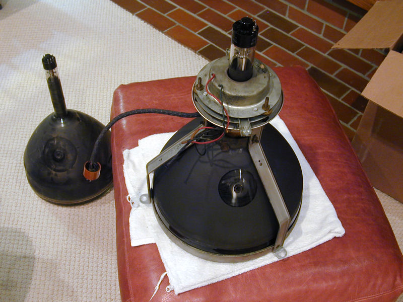
First Power
This photo shows the chassis on a workbench, connected to the picture
tube in the cabinet using extender cables.

I powered up the TV, watching the meter on my variac to make sure it wasn't
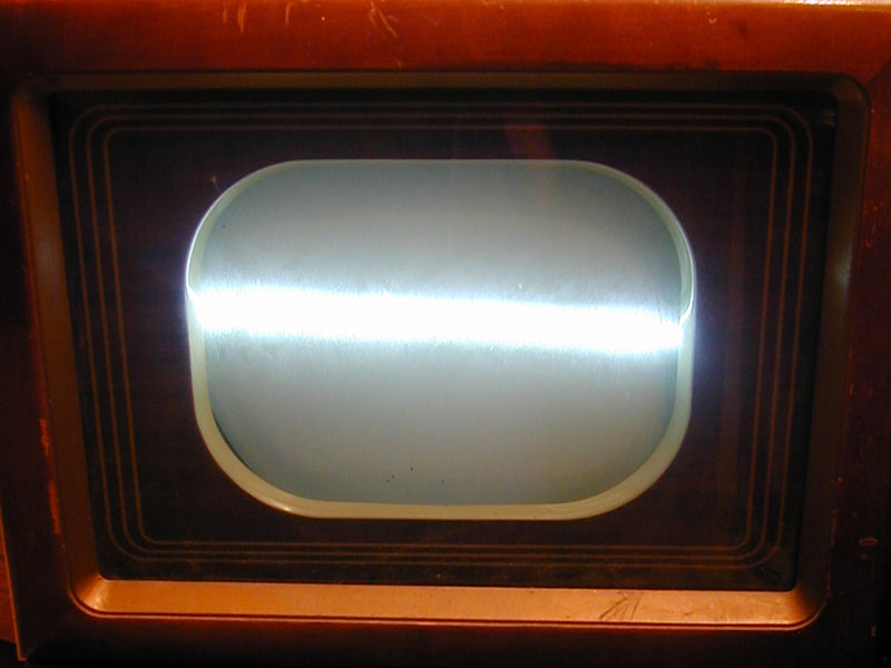
drawing too much current. No problems there, but the picture wasn't so hot.

The bright horizontal line means that the vertical sweep section is completely
inoperative. On the positive side, we have full horizontal deflection and
plenty of brightness, so a number of things are working correctly.
My tester had already shown that the picture tube is good. A bright screen with normal width
means that the flyback transformer is also sound.
Incidentally, if you ever power
up a TV and see an angry horizontal line like this, don't play it for more
than a few seconds, to avoid burning a dark line in the picture tube.
Fixing the Vertical
Before looking at the TV chassis, I checked the yoke extender cable. This was a recent
purchase that came along with a Tele-Check substitute CRT, and I had
never tried it before. A quick check with an ohmmeter revealed a problem: one
of the cable leads had never been soldered correctly to the pin in this plug:

Fixing the cable took only a few minutes. I also peeked around the vertical circuits
for obvious problems, and noticed
three flat black capacitors that I had missed in the first go-round. These, along
with three resistors, comprise the television's vertical integrator. Since they're
all connected, I replaced all six components.


Despite the square shape, those are molded paper capacitors, not mica caps. They
are unreliable and should always be replaced. For more details about capacitor types,
see my recapping article. (The photos also show a bumblebee cap that I had
missed, hiding behind the width coil; that was eventually replaced, too.)
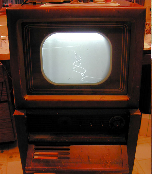
We have vertical deflection! The raster fills the entire screen,
with plenty of brightness.

The slanting lines coming down from the top are retrace lines, common
in some 1940s TVs when you turn up the brightness too high.
The squiggly trail down the center seems to be related to those lines.
I won't worry about it until I'm looking at a screen with some picture content.
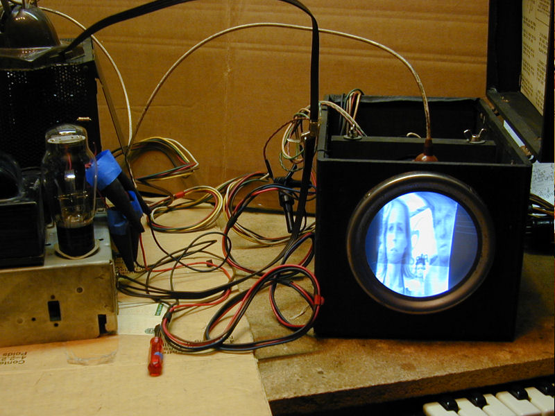
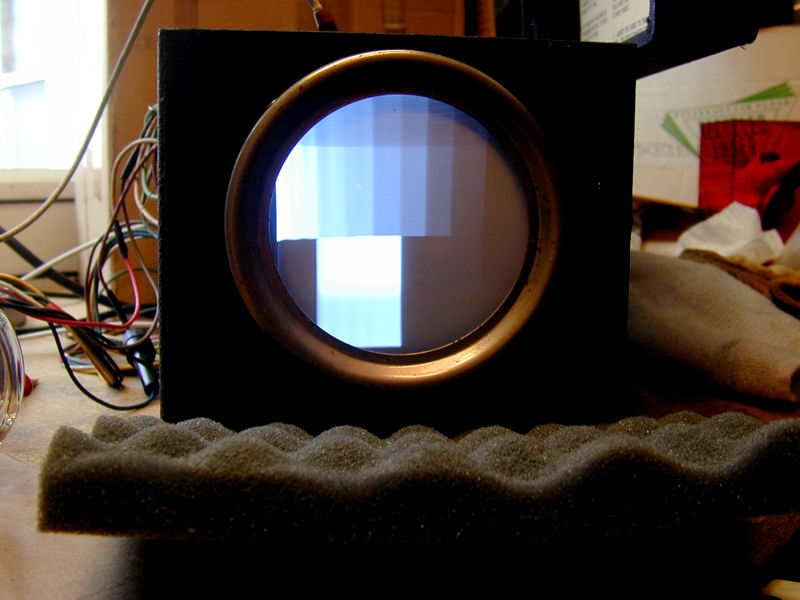
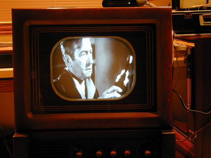
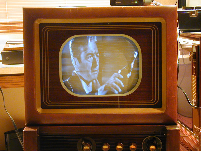
First Pictures
Speaking of the Tele-Check, here's mine in action, substituting its 5AXP4 picture
tube for the big one in the 49-1240's cabinet.

This is a coherent image and it proves that our RF, tuner, IF, and
video sections are working. The screen looks too tall and narrow, but
I don't care about that when using the sub CRT. The 5AXP4's purpose is to
let me power the TV on the bench with everything
accessible for testing purposes, not to display perfect screen geometry.
For that photo, the TV was using a rabbit ear antenna and receiving
a signal from my home TV transmitter.
That signal is fairly weak out in the workshop, which offers a good
real-world test of a TV's sensitivity.
Putting the chassis back in the cabinet somewhat later, I hooked up
my pattern generator and saw this:
Getting closer! This crosshatch pattern isn't too shabby, considering
that I haven't yet done any of the usual screen geometry adjustments. The center
dot is almost centered. The vertical and horizontal linearity (up-down and
left-right proportionality) are reasonable. We have plenty of brightness
and good contrast. Yes, the yoke is tilted, but that can be
leveled in a couple of minutes.
The bending in the top few lines is a little more troubling.
I was able to correct it by adjusting the horizontal frequency coil, but
the horizontal locking range was razor thin and turning the
vertical hold control messed up the horizontal, an unusual interaction.
After playing the TV a little longer, two more symptoms appeared.
I could hear a distinct ticking sound from the rear of the flyback
transformer—never a good sign, since arcing in the flyback
can destroy that hard-to-find part.
The squiggly trace also reappeared if I increased the brightness
enough to see retrace lines:

It's almost as if the squiggle is "falling off" the bottom-most
retrace line and then trailing downward. I'm not sure if I have
two unrelated problems, in the vertical and horizontal circuits, or one
problem that causes both symptoms (bending and squiggle).
The ticking sound worried me because it's often caused by arcing,
which can be destructive. Listening carefully with a plastic tube put to
my ear, I could definitely tell the ticking came from the flyback transformer,
seemingly from the laminated core rather than the windings.
I called on the VideoKarma forum for
advice and got various suggestions, including the idea that ripple
from the vertical section might be invading the power supply and disturbing the horizontal.
I was also reminded that my
BK Precision 1077B TV Analyst has a flyback testing
function.
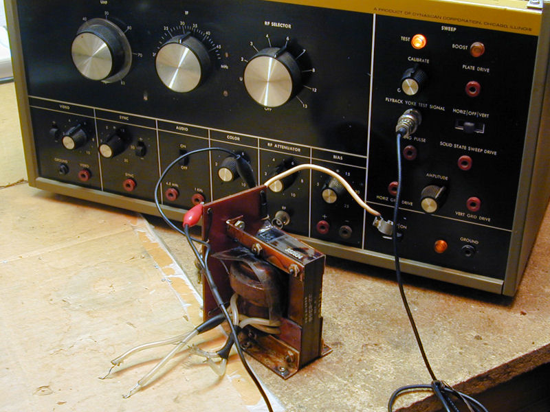
Investigating the Flyback
The flyback is a precious component, so I began by testing the resistance of its windings, comparing
the values given in the Philco schematic. My flyback read 134.6 ohms on the primary
winding where the schematic specified 240 ohms. Did it have a few shorted turns?
Given that ambiguous result, I decided to remove the flyback transformer and check it with the BK 1077B Analyst.
I let the test instrument warm up for half an hour to ensure that it had stabilized. In the
next photo, the Test lamp is illuminated, meaning that the flyback failed the test and it
presumably has shorted windings.

A discouraging result, but some VideoKarma folks suggested it's unlikely that a shorted
flyback would produce full horizontal deflection and normal high voltage, as seen in my screen shots.
I didn't have any known-good flybacks lying around the workshop, but it happened that my
RCA 721TCS chassis was sitting on a shelf while its
cabinet was being refinished. Bringing that chassis into the workshop, I tested the RCA's
flyback with the 1077B, carefully following the instructions in the manual, and again
got a failure indication.
As you can see in my 721TCS article, the RCA
creates a beautiful picture and its flyback has no apparent problems. Perhaps my 1077B's
flyback test simply isn't accurate. Although I restored the 1077B to the point where
it produced nice test patterns, I had never tried its flyback test function, so the
jury was out on that.
I reinstalled the flyback and resumed looking in other directions, including voltage
and resistance checks throughout the vertical and horizontal sections. Later on, I
learned from a VideoKarma member that the 1077B simply can't test a flyback with
a laminated iron core, such as mine. My RCA 721TCS flyback has the same type of core,
so comparing that test with the Philco was also fruitless. (I could have saved a lot
of time if the BK Precision manual had mentioned that the test works only for
certain types of flybacks!)
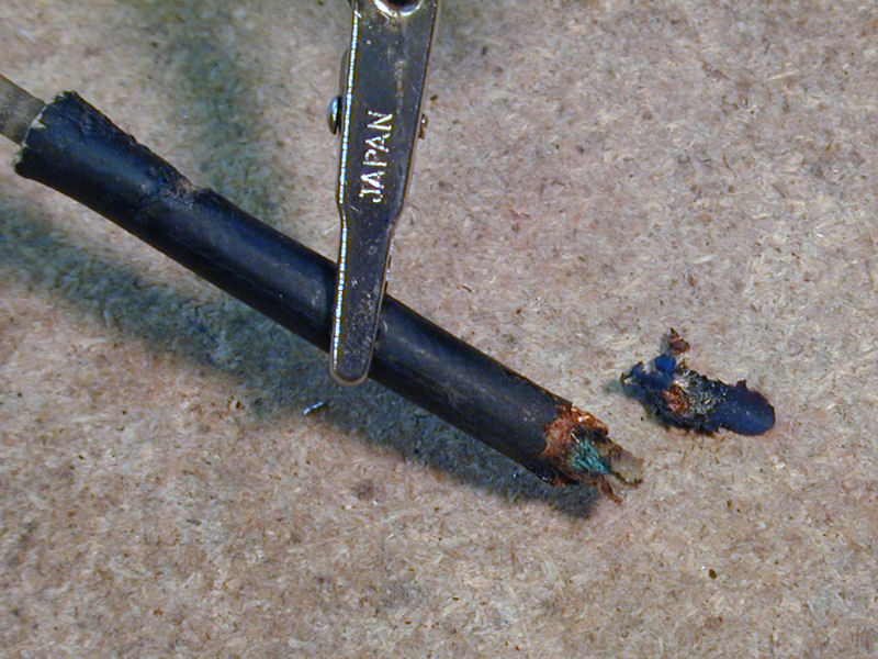
When removing the flyback leads earlier, I had discovered that the high-voltage anode
lead for the picture tube was literally hanging by a thread.

The wire had corroded and all but one or two strands had broken off. I stripped back the
insulation a little and tinned the bare lead before resoldering it. I also
added a grommet where that lead exits the HV cage, to prevent flexing when
it is unplugged from the CRT.
Even though testing the flyback didn't solve the mystery, at least
I prevented a future problem with a broken HV lead. I also carefully dressed
the solder joints under the HV rectifier tubes as I resoldered the flyback
leads, making sure they were smooth to prevent corona problems (and the
arcing that can result).
Back to the Basics
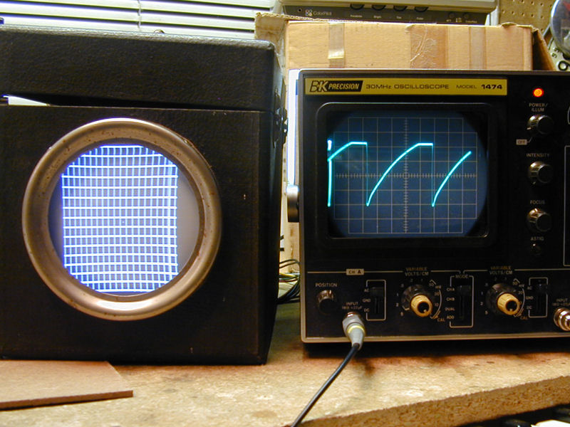
At this stage, I obtained the complete Riders documentation for this TV. In addition
to testing voltages and resistances, I fired up the oscilloscope and worked through
the troubleshooting sequence for the entire sweep section. For each of the listed
test points, I compared my scope's waveform to the model in the manual, taking
a photo for future reference.
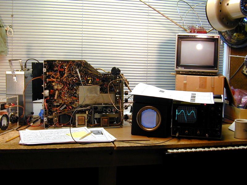
Here's the basic setup, with the television chassis propped on its side, variac and pattern
generator to the left, and substitute CRT and oscilloscope on the right.
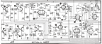
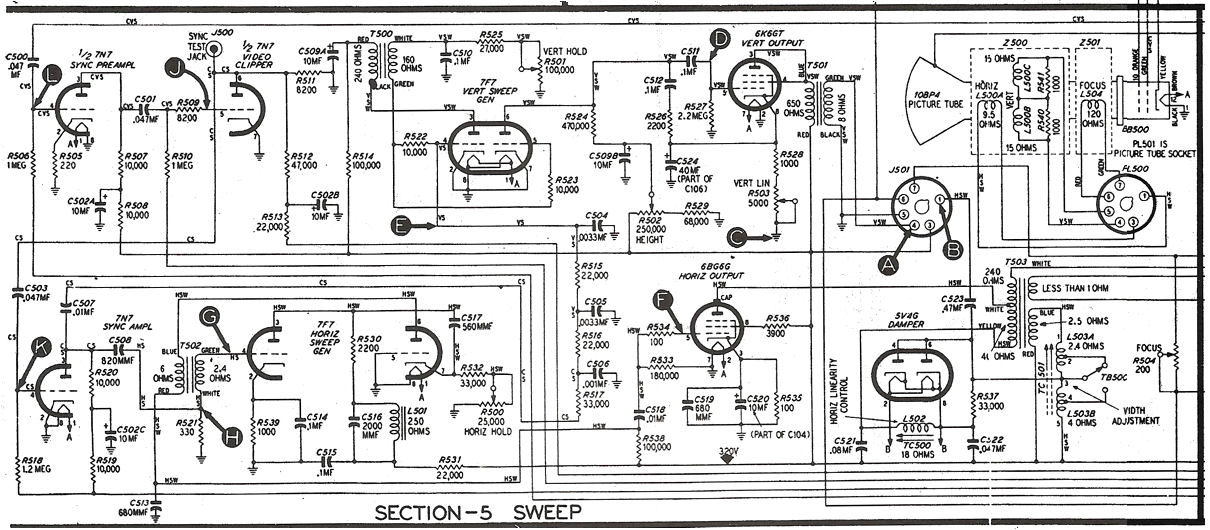
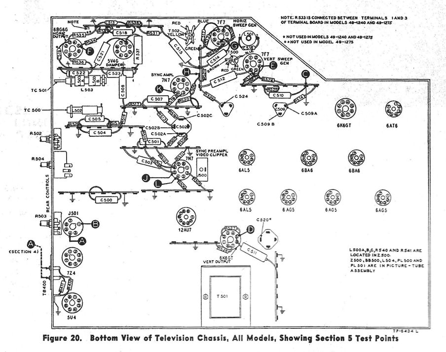
The Riders manual provides three diagrams for checking test points.
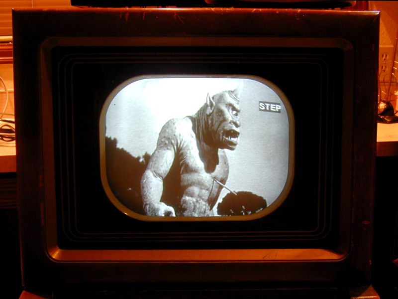
The first image below is the Sweep schematic including test points with letters A, B, C, and so on.
The second diagram shows those test points on the chassis,
with related components.

The third diagram lists each test point in order, giving a model oscilloscope
waveform for that point and suggestions for a cure if the waveform observed
in your television doesn't match the model. In the following excerpt, look
at the model waveform for Step 6 (Test Point F) and compare it to the
waveform observed in my TV.


During this phase, I also hit the books, comparing the Philco's sweep circuits to those discussed
in my old service texts, in case I had missed something obvious.
No smoking guns appeared, but
I replaced a few resistors that were somewhat (but not grossly) out of tolerance, as
well as a few mica capacitors in key positions.
After all that review, I felt a bit stumped. Many parts of the sweep
circuits looked normal, yet the problem remained.
As a way to organize my thoughts, I gathered up all of my notes, from both Sams
and Philco docs, and marked up a clean copy of the Riders schematic to show each
of my replacements, as well as test results from voltage and resistance checks
throughout the sweep circuits.
Before long, the answer leaped out. I had made a careless wiring
mistake early in the project, miswiring one end of a capacitor. Grrr!
Fixing the mistake took about sixty seconds, resulting in a bright, sharp,
stable picture. The ticking sound also stopped.
The mistake must have happened during a moment of inattention while recapping.
In this television, capacitor C512 connects to the grid of the vertical sweep generator
tube. When replacing it, I had erroneously connected one end to a component
in a horizontal circuit, instead of the correct destination.
How could this happen? Many of this TV's components are mounted on crowded
terminal strips, and components located on adjacent terminals may form parts of
unrelated circuits. Instead of the correct terminal, I had soldered this cap's lead to the next terminal over.
Embarrassing, but the mystery was solved. With vertical and horizontal signals tripping over each other, small wonder that the picture was a little scrambled. On the positive side,
this little detour confirmed that there's nothing seriously wrong with my TV, especially the flyback,
and boning up on sweep issues was also useful. You can never learn too much!
If you're curious about the ticking, VideoKarma member teevee had an interesting
theory: the intrusion of vertical signal impaired the beginning of the horizontal
sweep, and the ticking was the sound of the horizontal sweep starting and stopping.
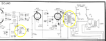
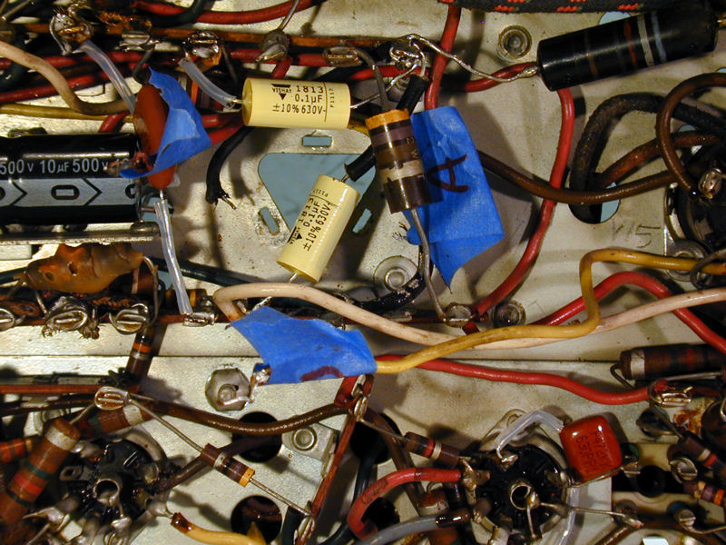
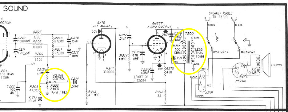
Replacing the Audio Output Transformer
When I had first tried the TV, the sound was barely audible with the volume
turned to maximum. To isolate the problem, I began with an old serviceman's trick.
With the set powered up, I turned on my soldering iron and briefly touched
the tip to the center terminal of the volume control potentiometer.
This test will produce a loud buzz through the speaker when the audio output section
is working normally. When I heard no buzz, I knew that a problem existed
somewhere between that point and the components "downstream:" in this
case, two tubes, a transformer, a speaker, and a few other components. In the
following schematic, the yellow circle on the left shows the volume control.
I had previously checked these tubes on my tester, and a quick re-test confirmed
that they were still good. Next, I checked the resistance of the windings
in the audio output transformer, T200 in the schematic.
The primary transformer winding was open. In restoring dozens of radios and TVs, this is the
first bad audio transformer I've ever found, but I guess anything is possible.
I placed a WTB ("want to buy") ad in the VideoKarma
forum Classifieds section, in case someone had a spare part.
Meanwhile, I temporarily substituted a
transformer from a junked radio so that I could operate the TV normally while
I continued the restoration. Here's the sub, mounted next to the original transformer.

1940s televisions have simple audio sections, so the characteristics of this
transformer aren't critical if it can survive the applied voltage.
This substitute worked reasonably well, but I wouldn't want to use it indefinitely
unless nothing else was available.
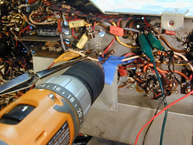
Luck was on my side. Fellow collector Eric H. provided a transformer salvaged from another
1949 Philco TV. It's an exact replacement for the original, with the same Philco part
number (32-8356). Here it is, perched by the other two and ready to install.

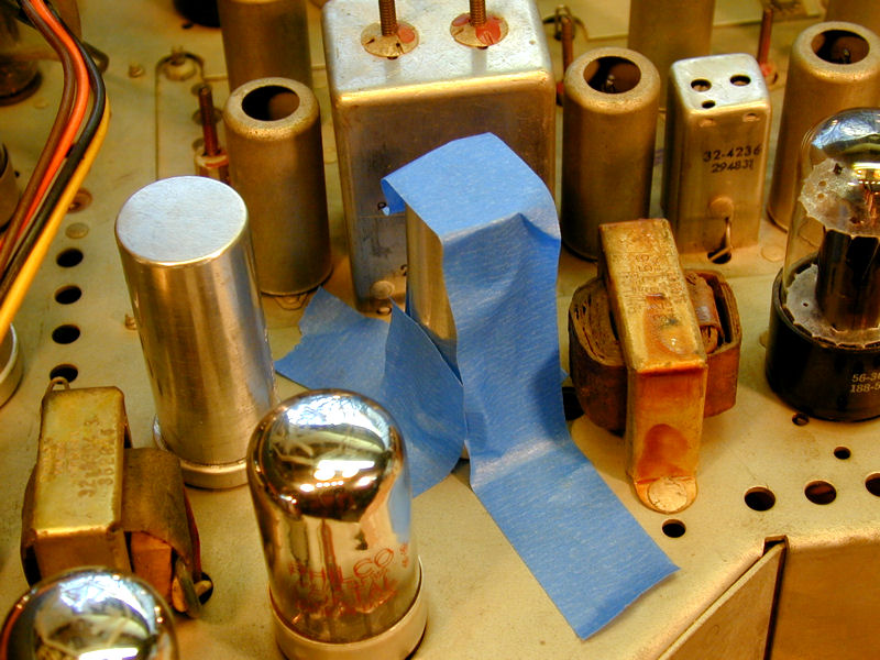
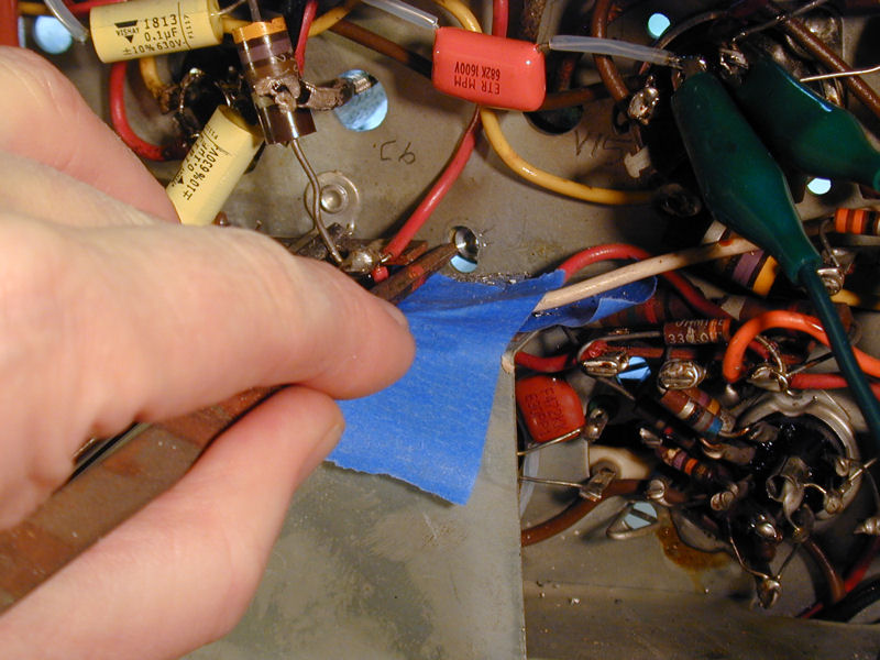
To remove the old transformer, I drilled the flanges off the rivets from underneath. The
blue tape protects nearby wiring and helps to catch metal shavings.

(In the previous photo, the three alligator clips are fastened to the
spots where the new transformer will be connected. This simple
reminder can help you to avoid wiring mistakes like the one described
earlier.)
A quick tap with a metal tool releases the drilled rivet:

A magnetized tool is handy for retrieving metal shavings from tight spaces:

Out with the old, in with the new! The replacement is on the right:

This transformer has three leads, but if you refer back to the schematic, you'll see
that its two windings need four connections. The fourth connection is made to
chassis ground through the transformer frame; on the old transformer, you can
see a short lead soldered to the frame. I'll burnish the bottom of
the frame around its screw holes to ensure good contact with the chassis.
The transformers have been swapped and my Philco sounds better than ever! The replacement
has been bolted to the chassis through the old rivet holes and its leads are
soldered underneath, just as before.

Out of curiosity, I may try peeling open the old transformer to see if it can
be repaired. If the break in a winding is near the outer surface, it may be
possible to resolder it without appreciably changing the inductance.
Bench Test and Adjustments
Now, I took the Philco on a shakedown cruise, playing it
for a couple of hours with a couple of different signal sources to make sure
it was stable. Confirming that it was, I made a series of adjustments with
the chassis in the cabinet.
I straightened the tilted yoke and then centered
the picture using Philco's "wobble plate" around the
picture tube neck. I adjusted height and vertical linearity, width, and horizontal
linearity, and I turned the AVC switch off and on while observing its effects on the
screen, to check whether it was working as designed.
Our little 1240 is looking good!

Cleaning the Safety Glass
Cleaning a safety glass is always satisfying. The rear
side of the glass is invariably grimy, as is the face of the CRT.
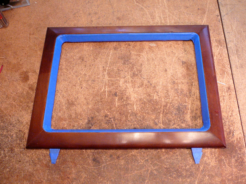
A removable wooden frame sits in front of the glass, with
two metal brackets that protrude through slots below. To remove the frame, you
take out two screws and then lift it off clips farther up on the cabinet.
In this photo I have pulled the frame and placed it atop the cabinet.
I circled the brackets and the slots that they slip into.

The safety glass and rectangular mask form a single unit, glued together along
the sides. The metal mask is painted with a brown wood grain
pattern and gold pinstripes surrounding the viewing area. The glass
is secured with two metal clips. In the next photo, I have removed
the glass and mask.
The picture tube looks much bigger when the mask is removed! If you need
to replace the CRT, it is drawn out through the front of the cabinet, hence
the removable frame.
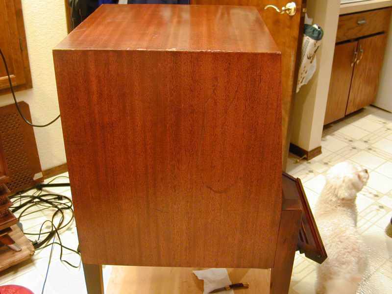
Cabinet Refinishing
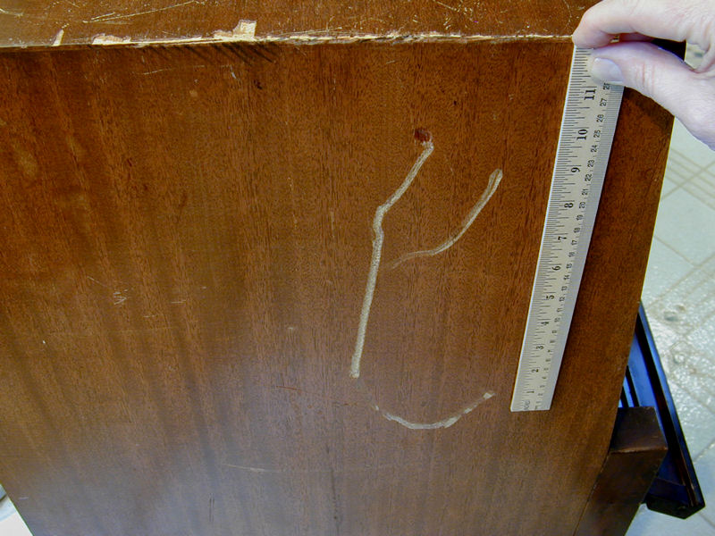
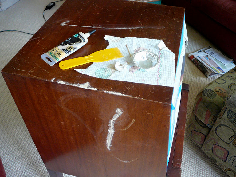
This cabinet was structurally sound but it had obvious defects. Here's
a big gouge on one side, before and after I did a quick touch-up:


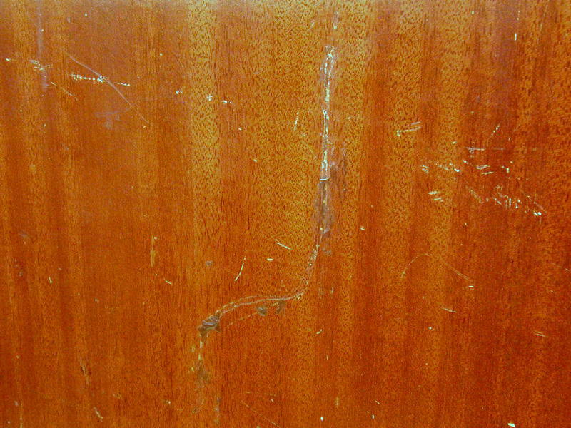
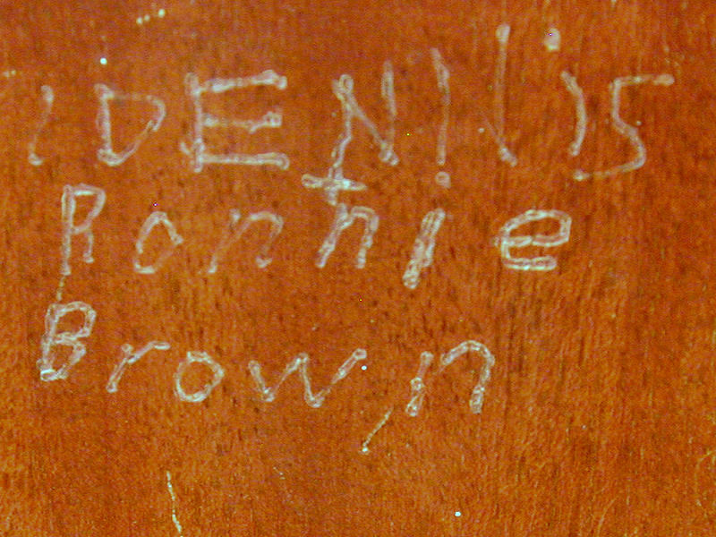
On the other side, a smaller gouge had been inexpertly concealed with something
like brown wax. The close-up shows another area where someone—presumably
a child—scratched his name in the cabinet. Hi, Dennis!


The rest of the cabinet had lesser scuffs and scratches, as well as a zillion
miniscule paint specks in white and red.
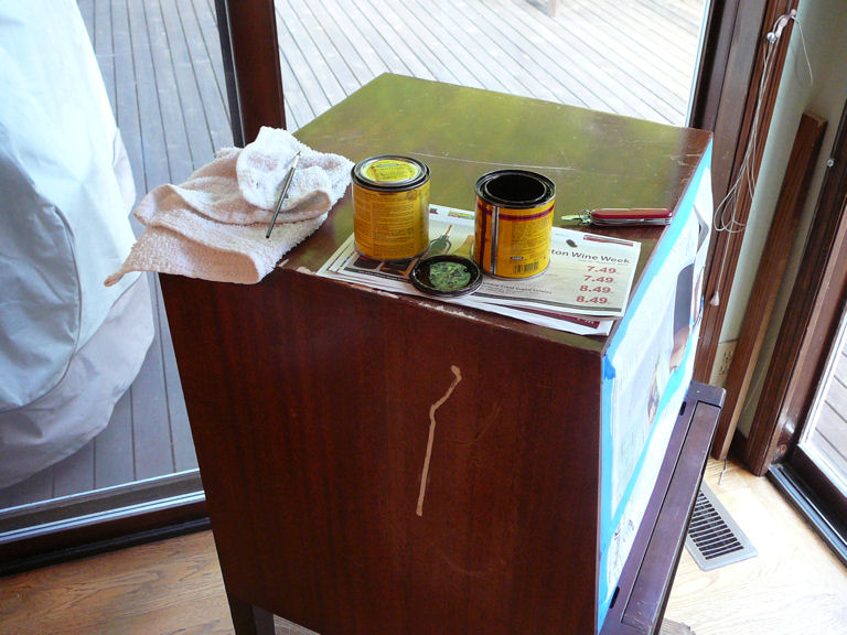
At this stage, I wanted to give the cabinet a quick refresh, making it
presentable enough to bring into the house for the winter. Next spring or
summer, after the weather improves, I can give it some more serious attention,
including patching the little veneer chips on one top edge and evening out
the finish.
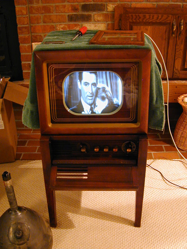
Here's the cabinet after one afternoon of work, with the chassis installed and playing.
The first step in my quickie refinish job was to thoroughly clean every inch of the cabinet.
After wiping with a rag wetted in mineral spirits, I went back over it again,
using gentle pressure and 0000 steel wool to remove paint dots and smooth light scuffs.
Where dots remained,
I soaked them for a while with a rag and mineral spirits and then rubbed some more.
A small number of very stubborn dots were addressed with steel wool and isopropyl
alcohol. This method is safer than trying to scrape the dots, which can do more harm
than good.
Where the little veneer chips had exposed the underlying wood and glue, I darkened
the blemishes with a brown marker designed for the purpose. Then I went over the
entire cabinet with Howard's Restore-A-Finish in the walnut color. Howard's isn't
my favorite product as a rule, but it's decent for quickly concealing a lot of
surface scratches.
DC Restoration and Retrace Lines
After playing the TV some more, I found the slanted retrace lines annoying. We
saw these lines earlier in the project when I had turned up the brightness to an
abnormal level:
I decided to look at the DC restoration circuit, whose purpose is to maintain
correct background levels in scenes of varying light and dark. When this
circuit misbehaves, overall picture quality degrades and retrace lines are
more evident.
In the Philco 49-1240, the DC restoration circuit is rudimentary, just
a diode and a couple of other components. I had replaced its capacitor in
the recapping phase. Finding some drifted resistor values in that neighborhood,
I simply replaced them all.
This improved the DC restorer's performance a bit, but I still found myself
wanting to turn up the brightness slightly beyond the point at which retrace
lines appeared.
I did some reading in vintage TV forums and found a link to an
article at the
Early Television Foundation website, describing a simple two-component
circuit (one capacitor and a resistor) that could be added to reduce retrace lines.
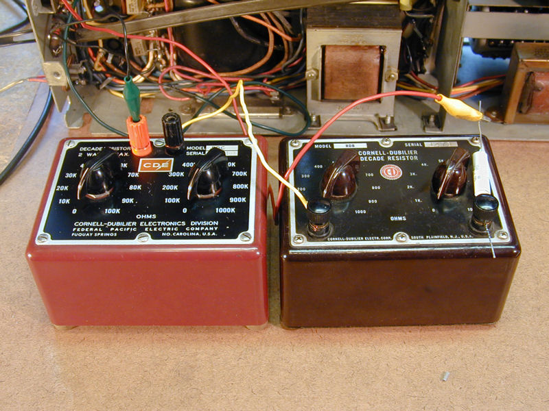
I decided to experiment with the circuit. In place of a fixed resistor, I connected
two "decade boxes" in series with the .1-mfd capacitor, allowing me to quickly
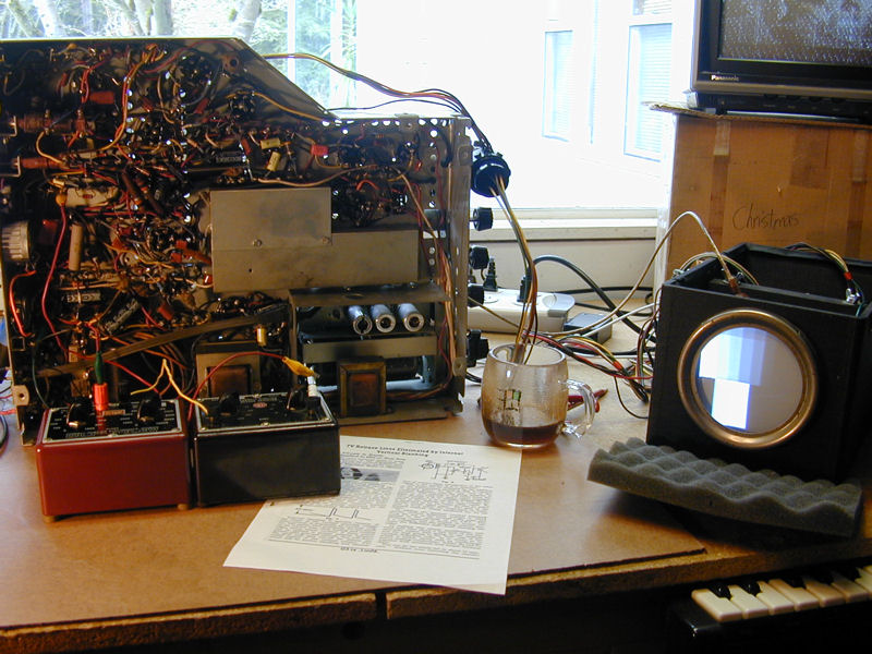
substitute various resistance values while watching the screen. The next photos show the
decade boxes and workbench setup.


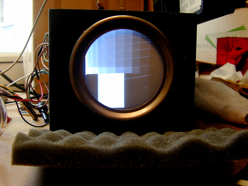
I adjusted the brightness to display obvious retrace lines and tried many resistor values.
The most obvious improvement came when I switched from zero ohms resistance to 10K ohms.
Slighter improvement occurred up to around 20K ohms, with negligible change beyond that
point. I decided to stick with the original value given in the article, 22K ohms. These
photos show the image on my test CRT with zero ohms resistance and with 22K ohms:


This simple modification lets me adjust for optimum contrast and brightness more
easily, without those pesky lines. As a rule, I don't approve of
"hotrodding" vintage TVs, trying to make them perform beyond their original
design limits, but this circuit appeared in a vintage magazine, after all, and it's so
basic that I could remove it in about 60 seconds.
Final Bits
Remember those rubber chassis bumpers that I wanted to replace? The new
ones arrived in the mail and now I'm ready to install the chassis and
back cover at last. The photo shows the old and new bumpers, along
with the chassis mounting screws.

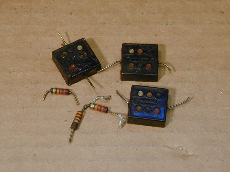
In honor of the day, I emptied my bag of replaced components. That's
40 capacitors, 10 resistors, 4 bumpers and an audio output transformer.

That's most of the components, anyhow. There may be a few more that fell on the
floor and bounced under my workbench.
Not shown, either, are the innards from the electrolytic can capacitors
that I restuffed. I'm kind of a packrat, but not crazy enough to keep that stuff!
Death of a Picture Tube
About a week after I finished restoring the electronics, I turned on the Philco
to watch a movie and the screen suddenly went dark, although the audio remained
normal. When I put the chassis onto my workbench and tried it with my 5AXP4
substitute CRT, the picture looked bright and clear as usual. My Sencore CR70
said the 12LP4 had zero emissions, although it had originally tested (and
performed) like a new one. The CRT also passed the CR70's short-circuit tests,
so this problem was a little puzzling.
I had never seen a CRT fail so suddenly before, but this one certainly looked dead.
The question was, why? When I mentioned the problem in the VideoKarma forum,
Nick had this suggestion:
If the tester isn't finding the short, run the tube with the chassis
and note the voltages on all the elements (K, G1, G2, etc). You might
find that the grid voltage is significantly higher than it should be,
or the cathode is very low. In either case, this would drive the tube
out of conduction leading to the low brightness situation. I suspect
an open has developed in one of the elements of the gun, the voltage
measurements will confirm which one. If you find an open, some testers
have a "weld" function which can sometimes repair a fault like this.
Before reinstalling the chassis, I measured the pin voltages on my
5AXP4 CRT. They looked normal (duh), and the cathode measured about
40 volts DC when the picture was normal. As I turned the Brightness
control, that voltage went through a range of about 25-140 volts.
With the chassis in the cabinet, its underside is inaccessible, so I temporarily
popped the cap off the 12LP4 socket and replaced it. Now, I was able to
test the voltages reaching the CRT pins.

The other voltages looked normal, but the cathode voltage was zero at
all brightness settings, showing, as Nick predicted, that the cathode
element had gone open.
My Sencore CR70 manual described a last-resort procedure for welding an
open cathode and VideoKarma member bandersen reported that he had been
successful with that, but only after trying it many times.
I set up the CR70 to do the weld and then
rapped on the CRT neck until I saw a bright blue flash inside, indicating
there had been conduction through the cathode.
The first few attempts made a flash, but immediately re-testing the CRT
still showed zero emission. After about 15 tries, the tube showed
normal emission. Yay! Perhaps I had revived this dead tube, after all.
My delight was short lived. I left the tube on the tester for a few
minutes and the emission eventually dropped back to zero.
With nothing to lose, I tried the weld procedure again
and again. After many blue flashes, I finally got a weld that looked
stable. I hooked up a movie player (actually, my iPhone playing
through an RF modulator) and sat back to watch for a while.


After about ten minutes, the brightness suddenly dimmed and then gave out
completely. I guess the gap in the cathode is too big to
weld by this method.
Well, it was worth a try! Until 2011, when the last US CRT rebuilder went
out of business, I could have sent the tube to be rebuilt. Now, the only
solution is to replace it.
Replacing the Picture Tube
I obtained a working 12LP4 from Harry
Poster in New York. I tested it while still in its shipping box, to
make sure it had survived transit across North America. The emission looked
strong, as you can see.

On this TV, you remove the CRT through the cabinet front, after loosening
two CRT supports on the yoke and removing the safety glass. Three stout bolts
support the CRT's weight in the front. After you remove their nuts, the yoke
and support assembly can be removed along with the tube.

Before removing the assembly from the old tube, I took this photo to document how
to position the new one. If the new tube isn't installed in the same way, the
cables between the chassis, yoke, and CRT won't reach, and you'll have to pull
everything out of the cabinet and try again.

After you loosen one screw in the clamping band, the assembly
lifts up and over the CRT neck. Not shown in this photo is a thin band of
flexible material that provides a little padding between the clamp and the CRT bell.

In the next photo, the assembly is in place and I'm ready to install my new tube. The
center of the second anode connection is 4.5 centimeters from the
nearest support arm, just as when I measured it on the old tube.

Here's the new picture tube in action. I needed to adjust the centering
a little after reinstalling it, to position the image precisely inside
the mask.
The new CRT wasn't cheap, but this TV performs so well that I didn't
want to relegate it to the status of non-working "shelf queen."
At this writing (February, 2012), there is nobody in America who will
rebuild old picture tubes, and the sole remaining rebuilder worldwide
(RACS in France) recently announced that they will soon go out of business.
The old CRT cannot currently be revived, but I'll keep it
around, just in case. The Early Television Foundation in Ohio has
a rebuilding project
underway, and if that succeeds, possibly they could rebuild this
tube some day.
Completing the Cabinet
During the following summer, we finally got some warm, dry weather and I
completed the cabinet work. My quickie Howard's treatment had made the cabinet
look better temporarily, but after several months the color had faded
and the cabinet looked just about as bleached and scuffed as when I got the TV.
I began with the bezel that frames the screen. Here, after masking
the gold painted inner edge, I have given it two coats of toning lacquer followed
by two clear coats.

I let the fresh lacquer cure overnight and then reversed the mask to spray the
gold painted area. I happened to have two shades of gold paint on hand, so I
sprayed test patches on a piece of cardboard to compare the colors. The one on the right looks good.

Spraying takes only a couple of minutes. When you remove masking tape, pull
it slowly and horizontally with the surface, to avoid damaging
the finish.


Now, the bezel looks pretty good, and this color won't fade.

On to the main cabinet. I used wood filler to patch a few veneer chips and the deepest
gouges. This filler is water based and I don't have the right colors to mix with it,
so I'll color it later.

After cleaning off excess filler, I'm ready to color the patches with stain and
a fine artist brush.

Fast forward to the next day. I applied a coat of toning lacquer to even out the color
on the entire cabinet, followed by some clear coats for protection. I used gloss lacquer,
which gives a nice deep appearance, but the full gloss tends to accentuate minor surface
imperfections. I'll rub it down to a satin finish using 0000 steel wool.

After that rubdown, I gave it a coat of hand-rubbed wax. Now, the cabinet looks just right.
The finish has depth and lustre, but without that too-shiny "antique mall" appearance.
Quite a contrast to the scarred orphan that I hauled home last year.

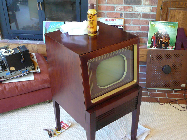
Finished at Last!
With that, I was ready to declare this project complete. After reinstalling
the chassis, I placed this little Philco in our family room where we can enjoy watching it.
A few years after I published this article, I was contacted by artist Michael Goetee, who
shared this childhood photo of him sitting by their family's Philco:

That Philco consolette was one year newer, a model 50T1443.
Years later, after the original TV was long gone, Michael created this model from memory:

It's interesting to note what features of the consolette were retained in childhood
memory. You can view more of Michael's art at his website.
|


