RCA Model TM-10 Color Studio Monitor (1954)


The RCA TM-10 studio monitor was contemporaneous with the legendary
RCA CT-100 television and it uses
the same 15GP22 color picture tube. Built for
broadcasting stations, it was designed the produce the
finest color TV pictures of its time.
The TM-10 is a rare bird. CT-100 TVs are scarce enough, with fewer than 200
existing and possibly two dozen of those in working condition.
Only a handful of TM-10 monitors are known to survive.
Description
Designed for monitoring the video in a TV station,
the TM-10 was furnished with a deluxe chassis to produce the highest
quality color picture, better than the consumer-grade
CT-100 television and other early sets.
In simplest form, the TM-10 monitor is similar to the CT-100,
minus the television's tuner, IF, and audio sections. It takes
a standard video input and has much in common with the CT-100
from that point forward, but with more elaborate processing.
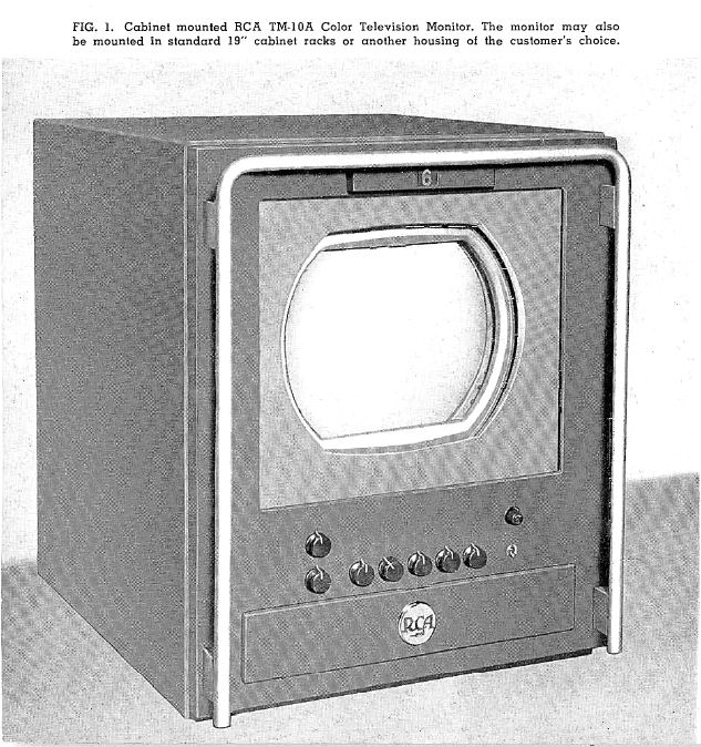
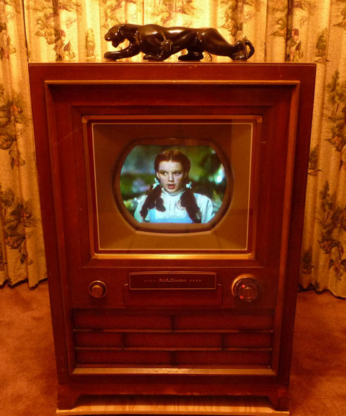
The following illustration shows a TM-10 in the optional steel cabinet. Next to it,
for comparison, is my CT-100 television.

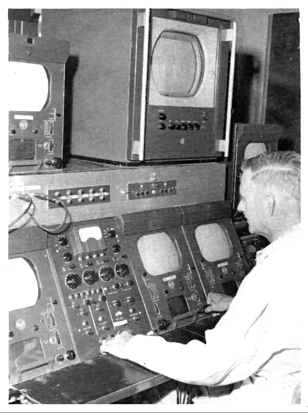
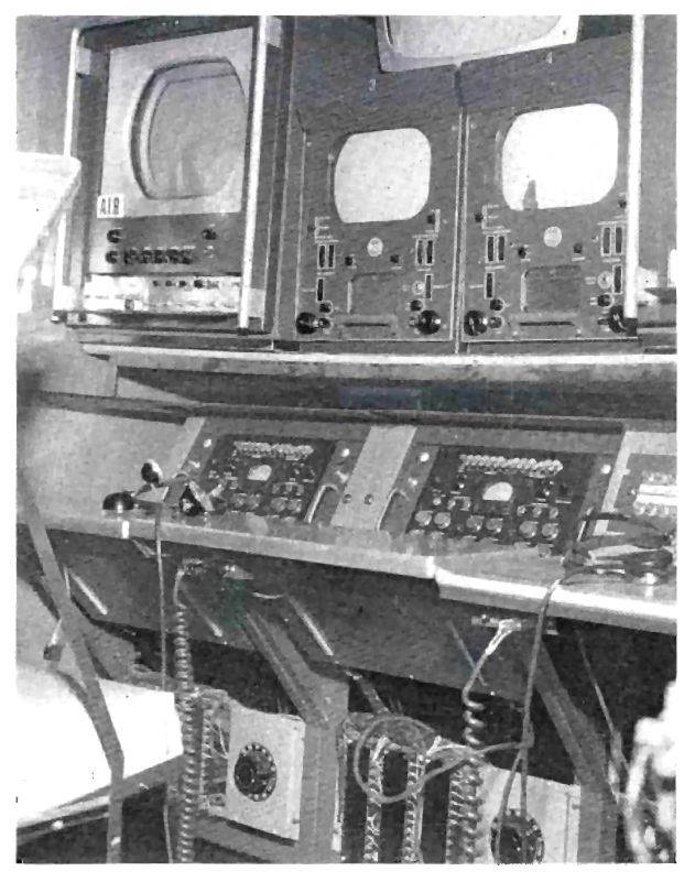
The next two photos show TM-10 monitors in the field. They are taken from
an article in the December, 1957 RCA Broadcast News, featuring station
KHQ in Spokane, Washington.
In the first photo, a TM-10 stands atop the KHQ studio control
console. The second photo shows another TM-10 inside the KHQ remote broadcasting
truck.
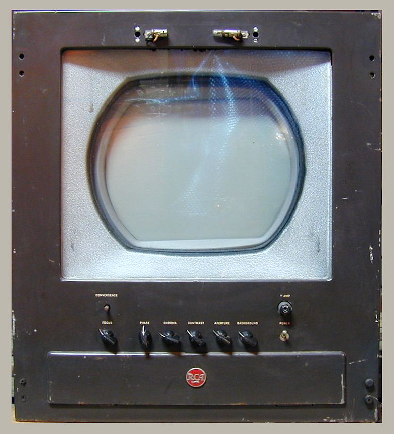
A glance at the front reveals that this is no consumer television.
The main controls are labeled Convergence, Focus, Phase, Chroma, Contrast, Aperture,
and Background. Many more controls are hidden behind the front service panel.
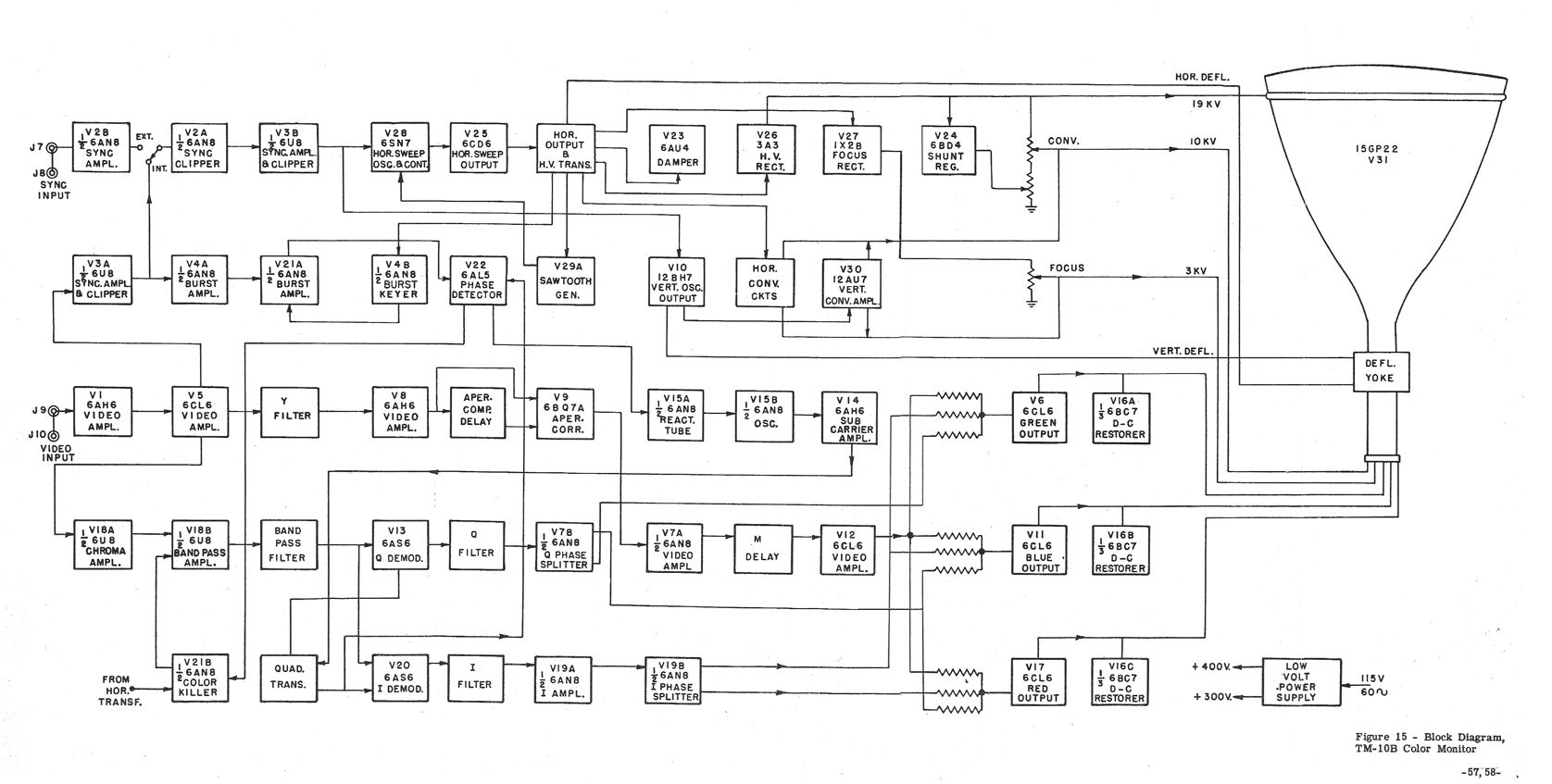
Below is a technical description of the TM-10 from the RCA service manual.
The first icon is the full block diagram and the second is the
accompanying text. For easy cross-referencing, open them in separate windows
or print them separately, since the text refers to elements of the diagram.
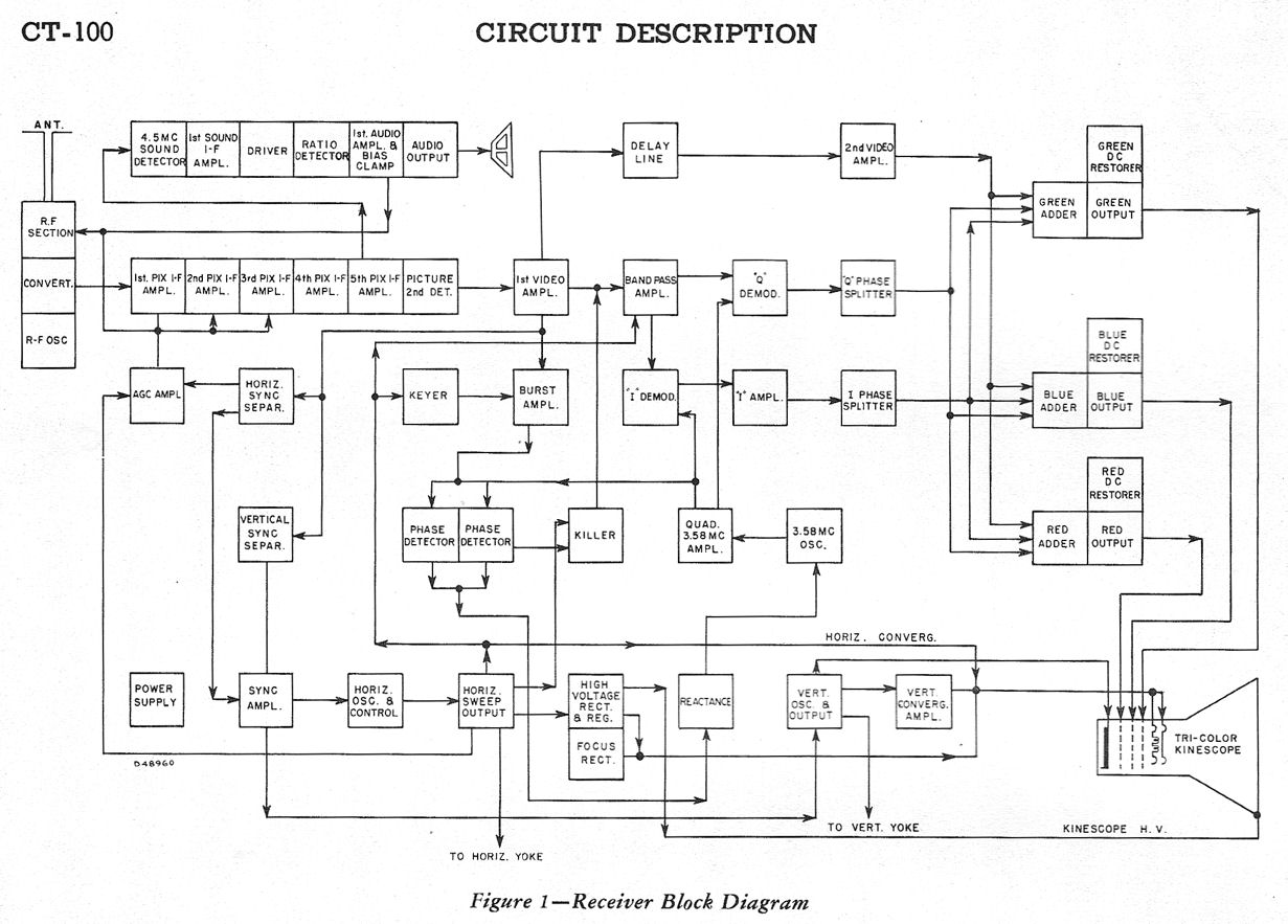
If you are familiar with the CT-100, you may enjoy comparing it to
the TM-10. Below is the CT-100 block diagram.
The super-sized TM-10 uses 31 tubes and a whopping 46 electrolytic capacitors.
Here is the tube lineup:
| Tube |
Type |
Function |
| V1 |
6AH6 |
Video Amplifier |
| V2 |
6AN8 |
Sync. Clipper / Sync. Amplifier |
| V3 |
6U8 |
Sync. Clipper / Sync. Amplifier |
| V4 |
6AN8 |
Burst Amplifier / Burst Keyer |
| V5 |
6CL6 |
Video Amplifier |
| V6 |
6CL6 |
Green Output |
| V7 |
6AN8 |
Video Amp. / "Q" Phase Splitter |
| V8 |
6AH6 |
Video Amplifier |
| V9 |
6BQ7A |
Aperture Corrector |
| V10 |
12BH7 |
Vert. Oscillator / Vert. Output |
| V11 |
6CL6 |
Blue Output |
| V12 |
6CL6 |
Video Amplifier |
| V13 |
6AS6 |
"Q" Demodulator |
| V14 |
6AH6 |
Subcarrier Amplifier |
| V15 |
6AN8 |
Reactance / Oscillator |
| V16 |
6BC7 |
Green/Blue/Red DC Restorers |
| V17 |
6CL6 |
Red Output |
| V18 |
6U8 |
Chroma Amp. / Bandpass Amp. |
| V19 |
6AN8 |
"I" Amplifier / "I" Phase Splitter |
| V20 |
6AS6 |
"I" Demodulator |
| V21 |
6AN8 |
Burst Amplifier / Color Killer |
| V22 |
6AL5 |
Phase Detector |
| V23 |
6AU4GT |
High Voltage Rectifier |
| V24 |
6BD4 |
Shunt Regulator |
| V25 |
6CD6 |
Horizontal Sweep Output |
| V26 |
3A3 |
High Voltage Rectifier |
| V27 |
1X2B |
Focus Rectifier |
| V28 |
6SN7GT |
Horiz. Oscillator / Horiz. AFC |
| V29 |
12AT7 |
Sawtooth Generator |
| V30 |
12AU7 |
Vertical Convergence Amplifier |
| V31 |
15GP22 |
Tricolor Kinescope |
Here is the full schematic in two parts. To save these PDF files on your computer,
right-click on the icon and choose Save Target As.
The entire service manual is too large to include here, but if you would like a
photocopy, send me an email.
Finding the RCA TM-10
In October, 2011, I was contacted by an Ohio collector who said that
he had a couple of old TV monitors, one with a 15GP22 picture tube.
My ears immediately pricked up, since that would make it a cousin
of the CT-100 television that I had restored.
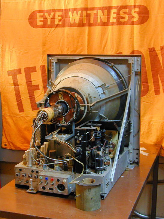
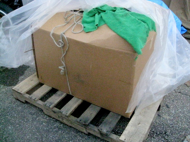
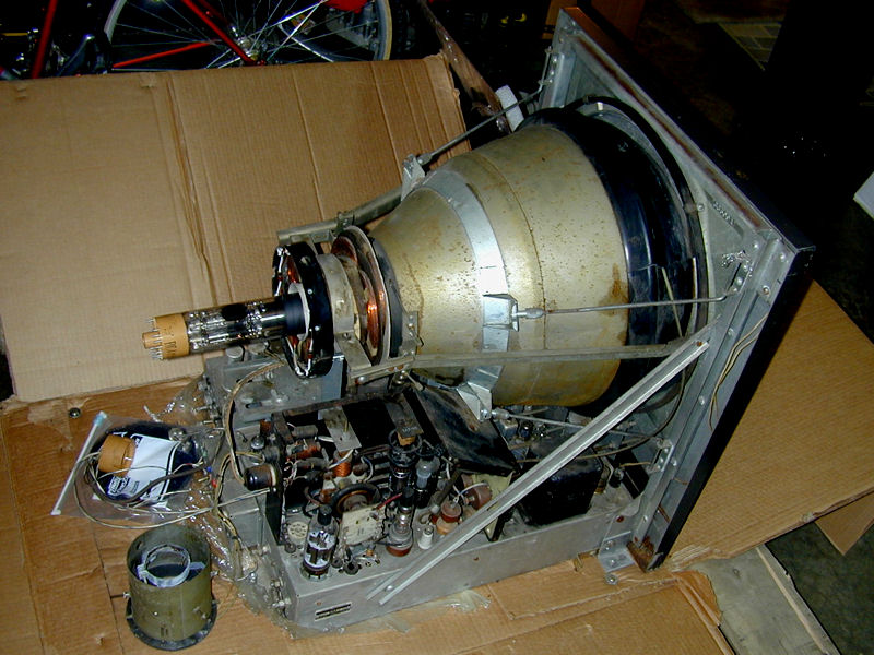
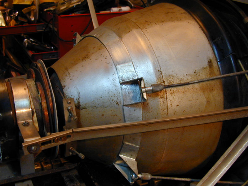
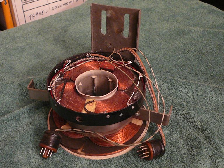
The photos that he sent were intriguing:


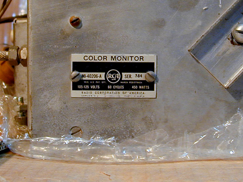
A little research confirmed that this was a type TM-10 monitor
equipped with a 15GP22, just like the CT-100.
After a short email exchange, we made a deal and I hired a shipping
company via U-Ship. The seller mounted the monitor on a pallet,
built a protective box around it, and delivered the package to
the shipping terminal in Ohio.


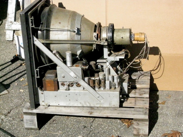
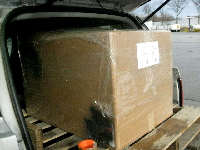
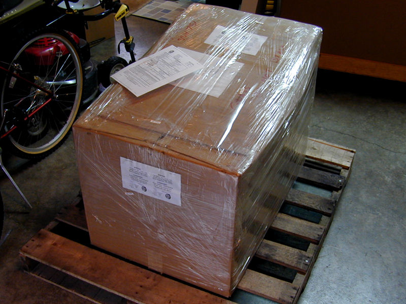
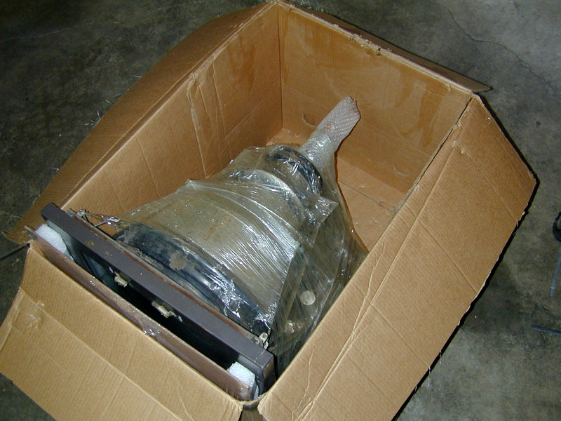
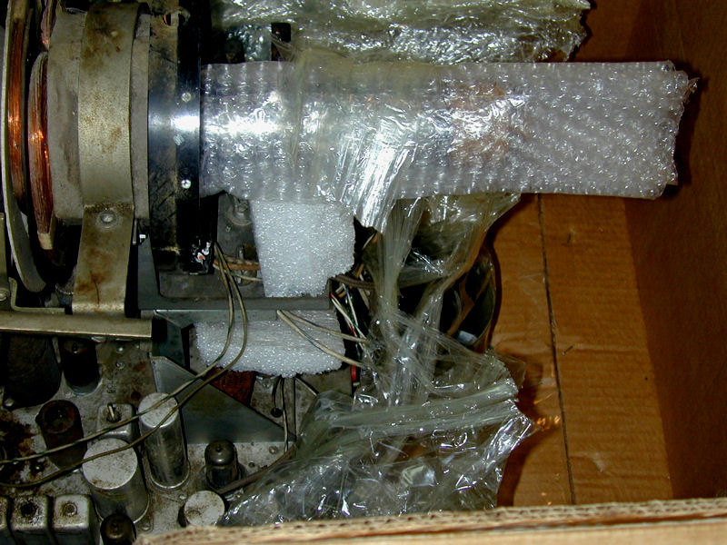
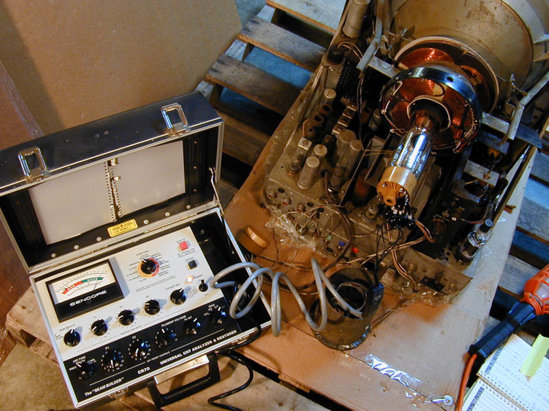
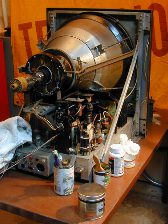
The next photos show the monitor after arrival, as I unpacked it in my garage.
The seller did a good job of protecting it for transit.


Before even removing the TM-10 from its pallet, I checked the precious 15GP22 picture
tube with my Sencore CR70 tester. If this tube had not survived the trip, I would be very
disappointed. Fortunately, it tested very strong on all three guns:

Great news. Full speed ahead!
Cleanup
With my son's assistance, we carefully lifted the monitor onto a sturdy metal
table and I began to clean it.
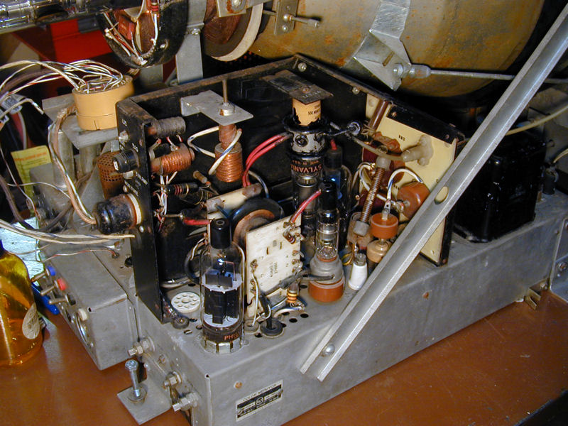
The high-voltage cage cover is missing, but
the components inside are cleaning up nicely.

Eventually, I'll need to fabricate a new cage cover. The HV components inside
emit lots of x-rays.
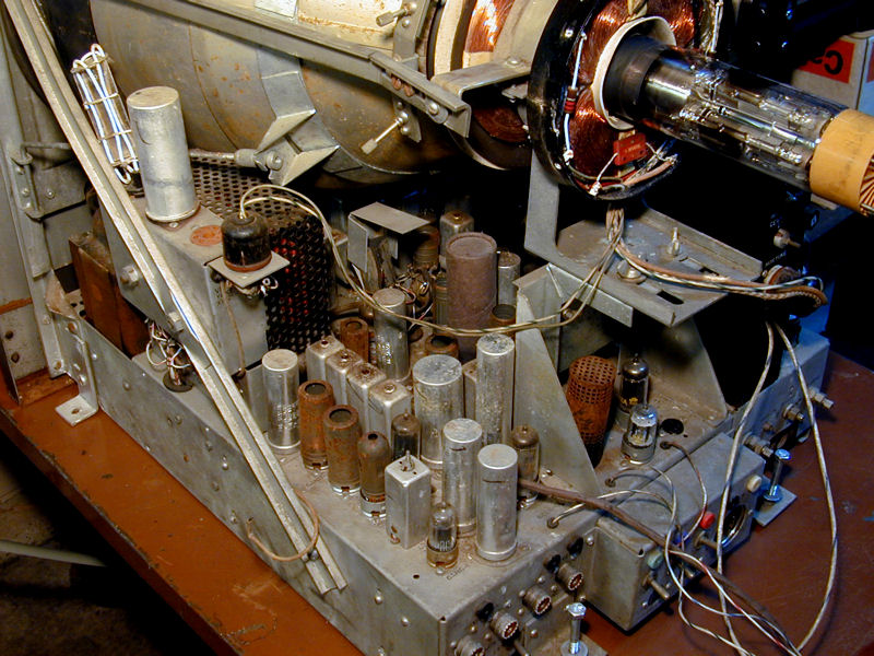
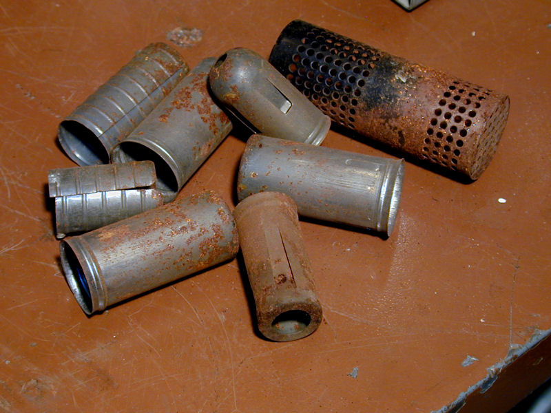
On the other side of the chassis, you can see some surface rust on tube shields and
the power transformer. This can be removed with Naval Jelly. The cover with
ventilation holes belongs to a ballast.


I have begun to clean the mu-metal CRT shield using Naval Jelly and Nevr-Dull.

Now the monitor looks more presentable, although there's plenty of cleaning left to do.
At this time, I also tested all of the tubes, replaced any weak ones, and cleaned their
pins. I put all 30 tubes into a plastic sack and set them aside for later. It will be a long time
before I can think about powering up this monitor.
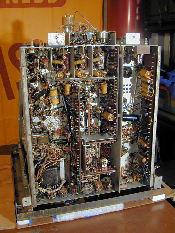
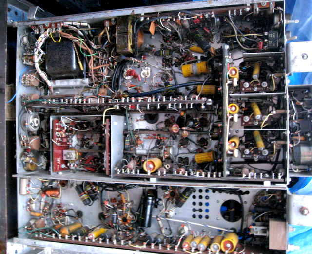
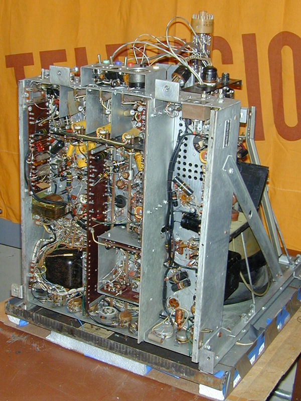
Inspection
I hadn't yet removed the CRT, but I wanted to look under the chassis. I
protected the front with layers of stiff foam and a sheet of Masonite board,
securely taped in place. Then I carefully laid the monitor down on its face.
The layout is interesting. Many components are neatly mounted in rows on long
terminal boards, more typical of military and industrial electronics
than a consumer television.
You can see a number of electrolytic capacitors in yellow cardboard cases. The chassis
also contains striped "bumblebee" type capacitors. All of these are
candidates for replacement, for reasons you can read about in my
recapping article.
The underside of the chassis is quite clean, overall.
Restoring this complex monitor will be a major campaign, so I'll form a battle
plan before I warm up my soldering iron. I have assembled a complete set of tubes, but many
capacitors will need replacement. I sat down with the service manual and
compiled a list of what's needed, looking carefully at electrolytics in cans to make sure that the
new caps will fit inside when I "restuff" the cans.
Preparations
This project remained on hold for about a year, while I completed some pending projects
and figured out how to work on this large and very heavy chassis. Even with the CRT
removed, it's too heavy to lift on to my regular workbench, which is tall enough for
me to work standing up. And with that giant chassis on the bench, there would be
room for nothing else.
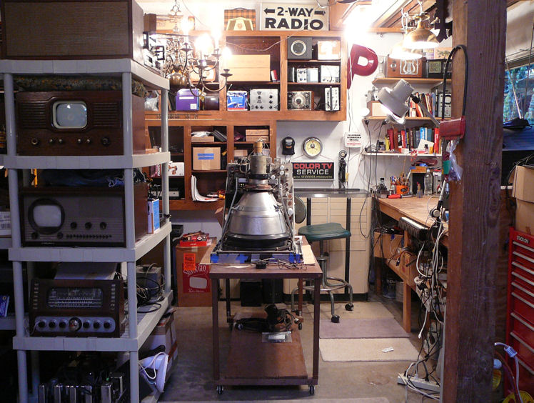
My solution was to make my metal table into a movable workbench. I built a sturdy
frame out of 2 x 4 lumber and 3/4-inch plywood, bolted wheels to the bottom, and then
fastened the metal table onto the frame. The next photo shows the TM-10 sitting on its dolly,
next to my "real" workbench.
I'll eventually need to remove the CRT to access components buried under the
bell, of course.
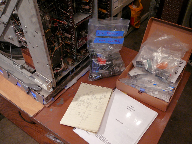
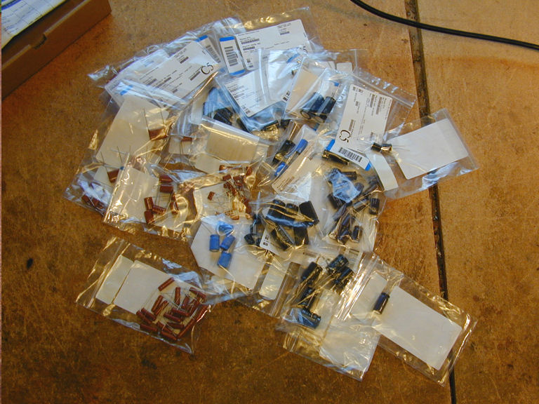
The next photos show some project supplies:


The labeled sack contains all of the tubes that I'll need—tested, pins cleaned,
and ready to go. I have also ordered many new capacitors and some inductors. CT-100 peaking
coils are notoriously unreliable,
The large 8 x 11 document is a copy of the RCA service manual, which I
obtained from fellow collector John Folsom. Next to it is the "little green book"
where I'll keep my restoration notes.
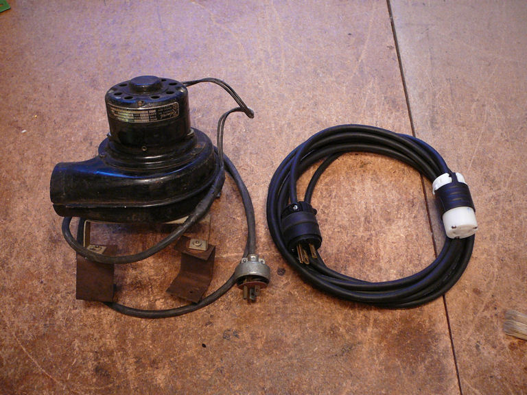
I won't need the following items for quite a while. On the right is a new cord
that I built to fit the monitor's industrial power jack. On the left is
a squirrel cage fan of the type used to cool these monitors.

The fan came from the estate of a retired engineer who had worked at a New
Jersey television studio. He accumulated other interesting items over the years,
including a partial chassis for the ultra-rare CBS model RX90 color television
(a CT-100 contemporary that also used a 15GP22 CRT). I don't know whether the fan was used in a
TM-10 monitor, but it's about the right vintage, so it's appropriate for this project.
Replacing Electrolytic Capacitors
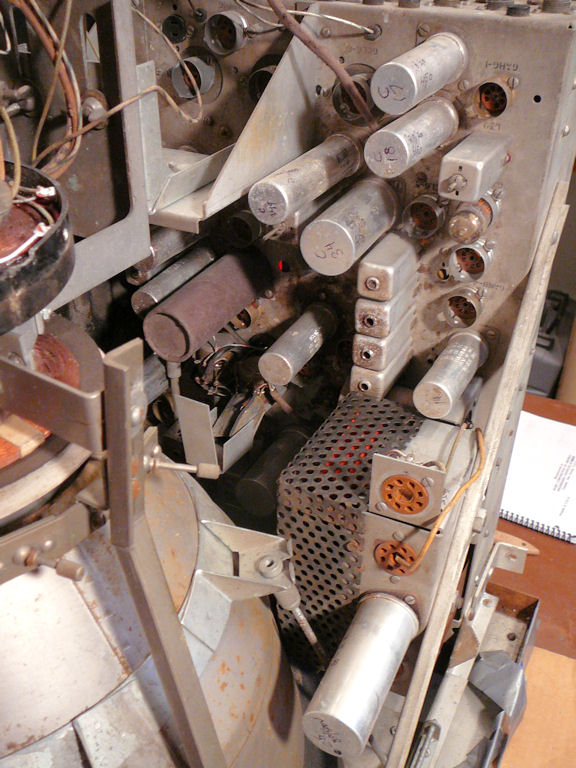
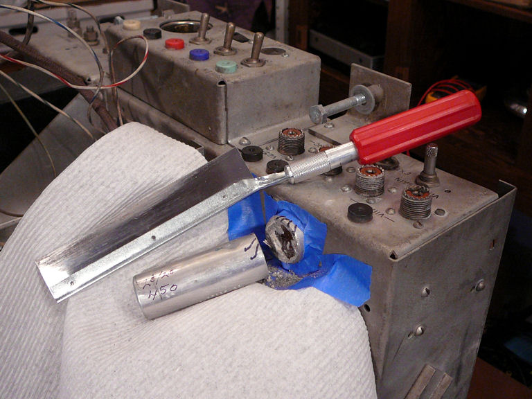
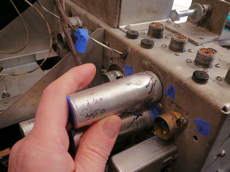
Here you can see about a dozen of the TM-10's electrolytic cans. Their tight placement,
especially in the chassis interior, presents a challenge. I'll warm up with
some easy ones, the C17 and C18 cans at the top in this view:

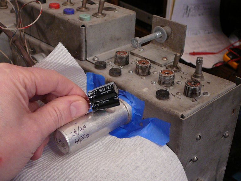
The replacement caps for C17 will easily fit in the can and cutting it at the base is straightforward:


I'll drill tiny holes in the can base and use them to connect the new caps to
the existing terminals under the chassis. Reaching those terminals will not be
so easy, though. In the next photo, I pushed the handle of a paintbrush up to
where those terminals are located. The terminals themselves are completely obscured
by other components.

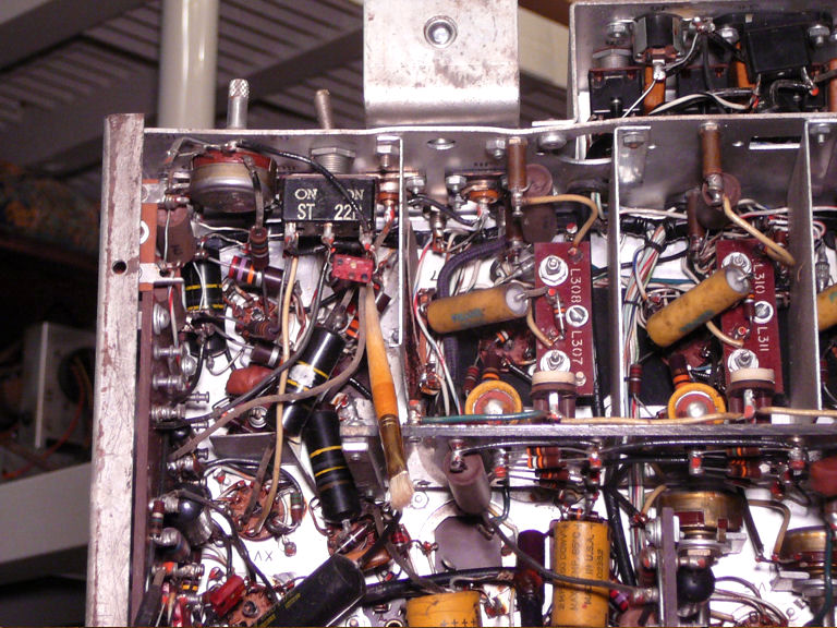
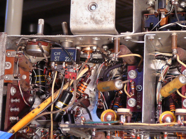
In the next photo I have removed a little shield and repositioned the pointer
so that it touches the can's base. If I unfasten that big toggle switch
(labeled "ON ST") and move it aside, I should be able to access that
area with long, thin tools, although not without difficulty.

In the previous photo, you can also see other buried components, such as a
striped "bumblebee" capacitor in the corner of the chassis. I don't
want to be needlessly invasive, but obviously reaching things in this
densely packed chassis will sometimes mean removing several items
temporarily just to reach one. I'll proceed slowly and carefully,
taking photos and sketching connections in my project notebook as I go.
Four new caps have been installed, two for each can.

The innards don't have to look beautiful as long as everything's wired correctly.
In the next photo, I have slid the old cans back into place just to confirm that
they still fit.

I'll wait to epoxy the cans back into place until I have powered up the set and
determined that things are copacetic. No sense getting carried away with cosmetics
at this early stage. When the time comes, I'll remove that little dent
and polish both cans.
Four electrolytics replaced—only 42 left to go! This is a large project,
so I'll try not to be daunted by the numbers, but just keep plugging along.
Where Next?
In most TV projects I work on the set by sections, starting with the power supply.
That also makes sense here, and now that I've gotten limbered up, I may as well
tackle those electrolytics, which are among the least accessible of all.
But first I'll replace those few bumblebee caps in the corner that I've opened up.
As long as I have removed the little shield and pushed the switch out of the way,
I may as well reach what I can before buttoning it back up.
That goes for resistors in this corner, too. In a densely packed chassis, it's
sensible to deal with everything in a particular area at once,
particularly when reaching one component means temporarily disconnecting others.
I'm not going to "shotgun" every resistor in this monitor—an
invasive and unnecessary procedure—but I will check them as I go, replacing
any that are significantly out of tolerance.
Removing the 15GP22 Picture Tube
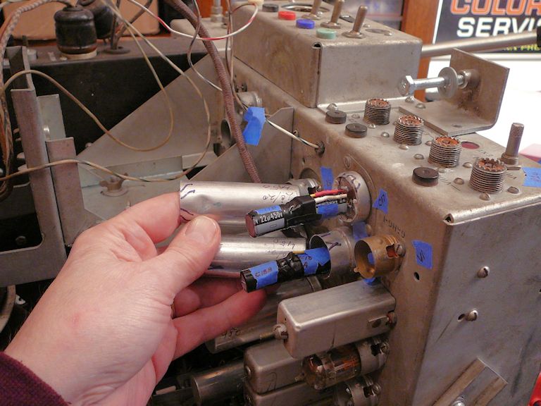
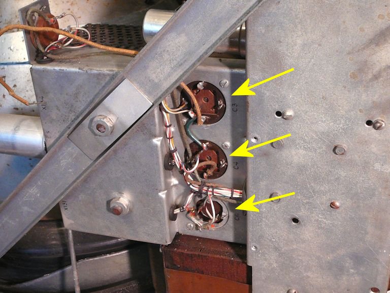
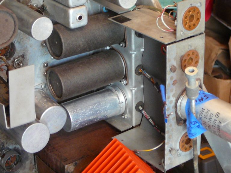
Replacing power-supply electrolytics is easier said than done. This photo shows the
bases of three important cans, C3, C4 and C6:

From a different angle, we see that these cans are mounted on a little
subchassis that butts up against the metal CRT shield.

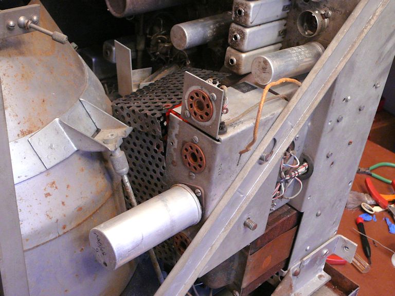
The subchassis contains two big, orange power rectifiers enclosed by a black
ventilated shield (the shield is slightly loosened in the previous photo). There's no clearance between
this stuff and the CRT. Until the CRT has been removed, it's impossible
to slide that shield off, much less reach the capacitor cans buried
farther inside.
I'll remove the yoke and shield from the CRT, working from the top down.
The yoke assembly is secured by four screws.

I do have the cover that belongs on the end of the yoke. Like virtually all of these
covers, it has warped and begun to fall apart, but a replacement is easy to make
from a paint can lid.

Removing the yoke exposes the four convergence magnets, which are held
on little adjustable stalks near the CRT bell.

Two of the tiny magnets on those stalks are missing. I guess they fell out
sometime during the last few decades. I'll need to find or fabricate replacements
later on.
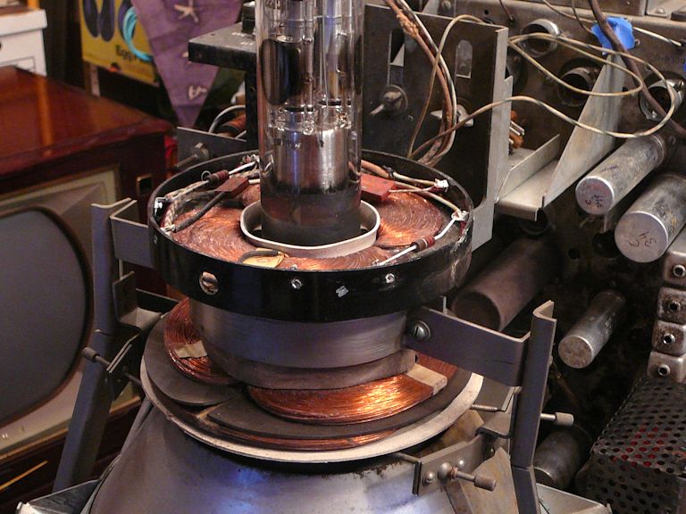
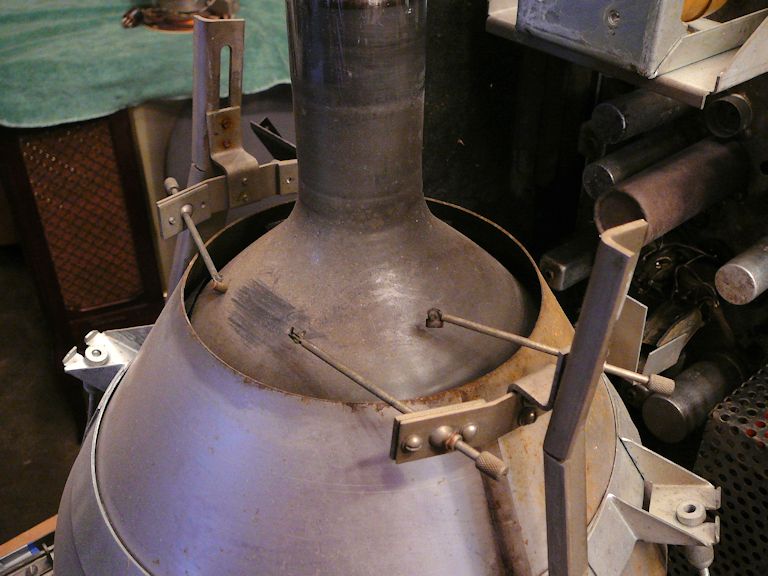
The stuff in the next photo looks familiar. The heavy mu-metal shield, collar and stanchions
are exactly the same in the CT-100 television.

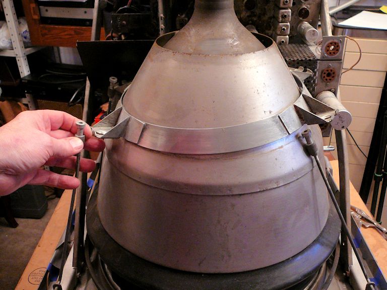
After the collar and shield are removed, the CRT simply lifts up.
At least, it lifts up in theory. The face of my CRT was securely
stuck to the cabinet by its rubbery 1,000-year old gasket and it
took a lot of extremely careful prying, pushing, and tugging to free it.
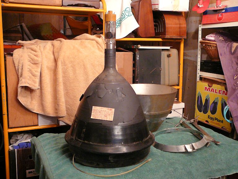
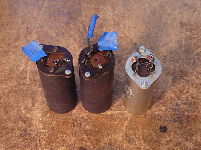
At last, the 15GP22 and related parts have all been removed.
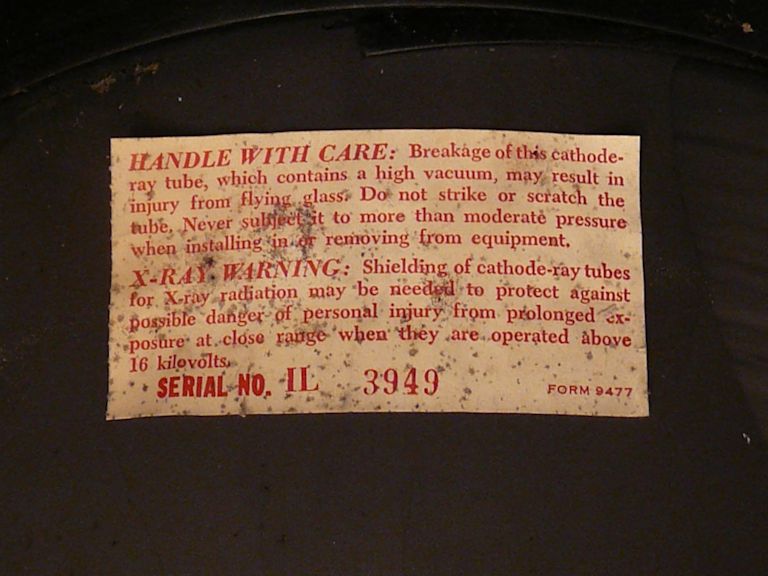
Some of the conductive aquadag coating is flaking off the CRT bell, but
that's a common problem and easily remedied.

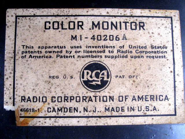
When I redo the aquadag,
I'll preserve this label, showing the tube's serial number.

Back to Recapping
With the CRT out of the way, I pulled one of the big orange selenium rectifiers,
and now it's possible to reach those three electrolytic cans.

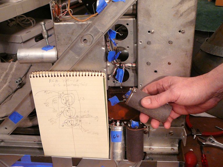
A short time later, three cans have been removed. I drew a diagram of the
connections and tagged the disconnected wires with numbers coded to the diagram.

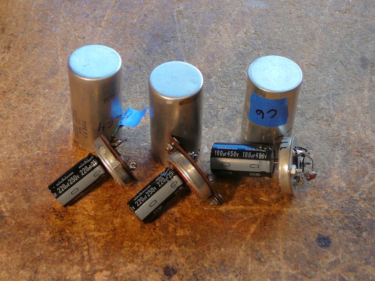
In the next shot, the new caps have been wired and I'm ready to replace the cans.

The C6 can contained two caps, 80 mfd and 10 mfd, wired in parallel. That's equivalent
to one 90-mfd capacitor. (Perhaps RCA had a bunch of 80-10 caps on hand and decided
to use them this way to get 90 mfd.) I'll replace the two paralleled caps with a single 100-mfd cap,
which is within the specified tolerance.
The cans have been glued back onto the bases with epoxy and I slid the cardboard
covers back onto C3 and C4. All three cans are ready to reinstall.

While the cans were out, I took the opportunity to scrub the immediate chassis
area with Naval Jelly and a cleaning pad, to remove any dirt and corrosion.
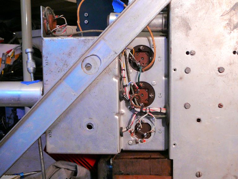
In the next photos, the restuffed cans have been mounted on the chassis and
rewired as before.


As the first photo shows, these cans are secured with screws and nuts, and
there's no way to reach your fingers in to hold the innermost nuts
while screwing them back on. Nor is there room to fit in a nutdriver or any
other tool. I used a little gob of poster putty to temporarily stick each nut with its lock washer onto
the can base, right above the screw hole. Then I could gently thread the screw into
the nut from the other side. After securing the nut, I pulled off the poster putty with a long tweezers.
Three more electrolytics replaced—only 39 left to go (groan). I won't document any
more of them unless they involve a special issue worth mentioning.
Replacing Selenium Rectifiers
The TM-10 uses two hefty selenium rectifiers in its power supply, similar to the CT-100.
These unreliable components will be replaced with silicon diodes.
In the service manual, someone sketched a small modification that adds two new
7-ohm, 25-watt resistors, R440 and R441, in series with the rectifiers. I assume
that they were added to provide some surge protection (solid-state rectifiers
deliver current almost instantly, compared to tube rectifiers).

I was debating whether to install these resistors or to use CL-60 thermistors, but
a fellow collector remarked that I should install dropping resistors in line with
the silicon diodes anyway, to compensate for their lower forward resistance. Those
dropping resistors will also reduce the surge, killing two birds with one stone.
I'll need to make sure that the new components have adequate ventilation.
This previous photo shows that the big rectifiers were mounted very snugly
in their cage, leaving insufficient room for additions:
I'll remove the old rectifiers and keep 'em with the monitor for old time's sake. Then
the new power resistors will be well ventilated. I'm not worried about appearance;
when the cage is back in place, you won't be able to see what's inside.
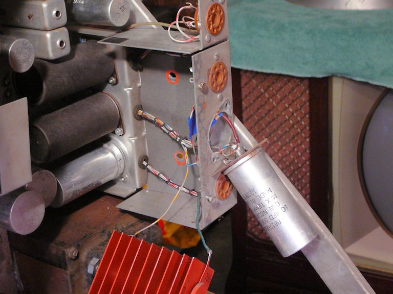
Mounted on the cage frame is the can electrolytic capacitor C5. Here, I have loosened
its base preparatory to restuffing it. This cap connects to rectifier CR2 and it makes
sense to treat everything inside the cage at once.

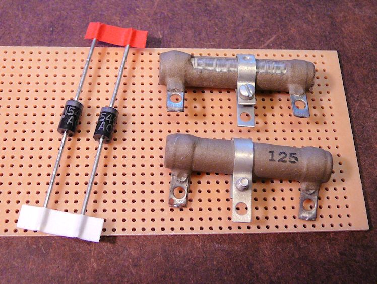
Conventional wisdom says the new dropping resistor should be something in the
neighborhood of 50 to 100 ohms, the exact value determined by measuring the
B+ voltage after installation and then adjusted as needed. I found some hefty
25-watt power resistors that are adjustable from 0-125 ohms.
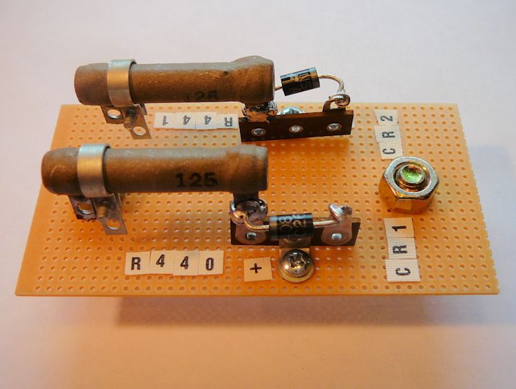
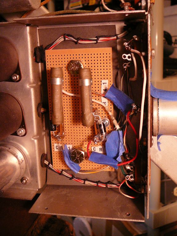
I mounted them with the type 1N548 diodes on a piece of project board.


The second photo shows one of two large bolts that run through the board. These
are located to match the chassis mounting holes for the old rectifiers.
The socket of the ballast X131 also connects to the rectifiers. In this photo, I have
finished restuffing capacitor C5, temporarily taping its can back in place, and
removed the X131 socket for access.

When wiring the new rectifier board, I used a heat sink to avoid damaging the diodes.

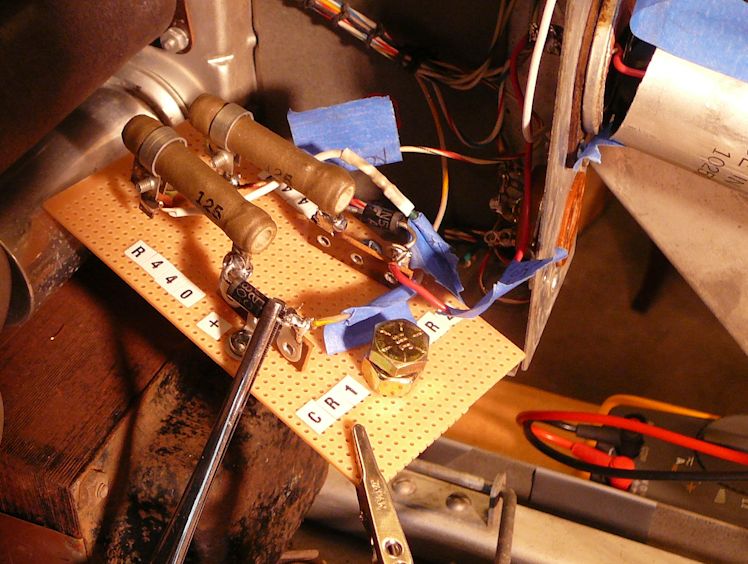
In the next photo, the ballast socket and finished rectifier board have been
remounted. The resistors are mounted topmost so that their heat won't toast
the diodes. I'll remove the little blue ID tags from the wiring before I
reinstall the cage.
I'm hoping that all of the work in and around this cage is done.
An Abandoned Repair?
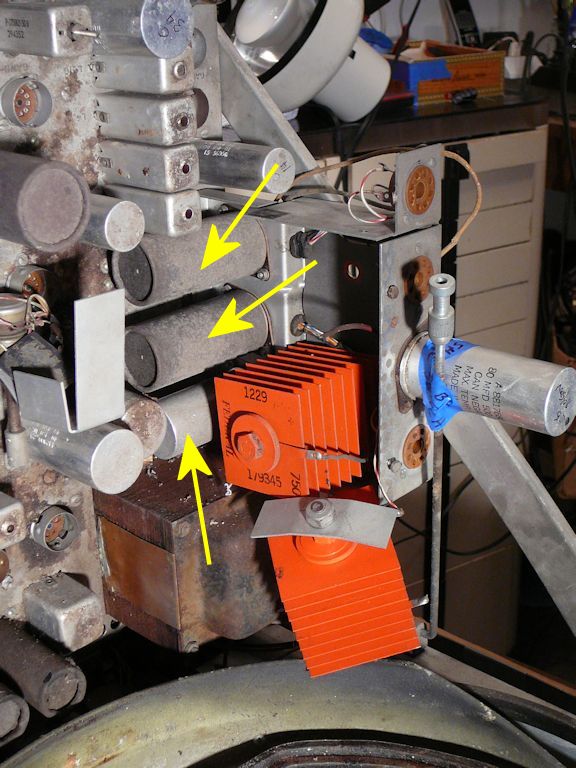
Installing the rectifier board was straightforward but now I have to
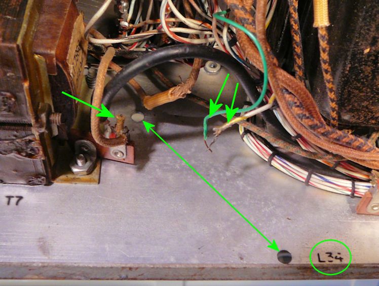
solve a mystery. When checking connections beyond of this point,
I discovered that the filter choke (L34) was missing. In its
location is nothing but a rubber stamp and two empty mounting holes.

Nearby are two loose wires, marked with arrows in the photo.
There's also a cut-off wire stub on a nearby terminal, but the intact wire
on that terminal connects to T7, the vertical output transformer, which
is not relevant to L34.
When I followed connections out from the choke, I discovered some
monkey business around two potentiometers: R3, the purity control, and
R241, the screen purity control.
The schematic shows that choke L34 leads to R241, which in turn
leads to R3. Inspection revealed that someone had disconnected both controls,
temporarily fastening their leads together. The 22-ohm resistor
mounted in parallel with R3 had also broken in half, a catastrophic failure.
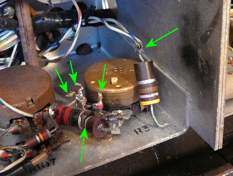
Here's a view of R3:

All of the wires have been snipped—or ripped—from the potentiometer.
The broken 22-ohm resistor is still attached to the control. Two wires have
been crimped together using one end of a salvaged 47-ohm resistor.
What's going on here? Perhaps someone began to fix a power-supply
problem and only got as far as disconnecting a few things, or possibly
he scavenged the choke for some other project.
The schematic shows that the purity yokes are dead ends: they
are supplied with current via L34, but nothing else depends on them.
I can finish restoring the low-voltage power supply and
even give it a basic power-up test with all tubes removed, but I'll
need to solve the L34 mystery eventually, if I want a good color picture.
A Promising Lead
One of the leads for the choke L34 was not hard to find. When I replaced the
electrolytics near the rectifier cage, this lead from the negative pole of
C3 had been left with nothing to connect to:

Nothing in or around the rectifier cage would need such a connection, so
this must be the choke lead. Someone pulled it out and left it hanging
for unknown reasons. I rethreaded it back through a hole in the chassis
and found that it's just the right length to attach to the missing choke.
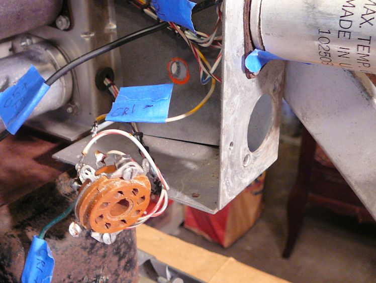
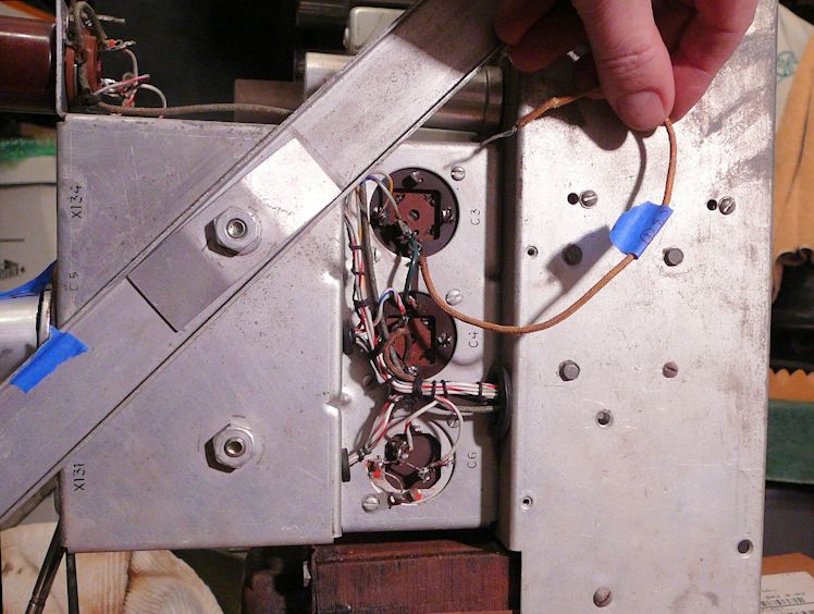
The second lead should connect to the screen purity control, R241. The next
photo shows that R241 is inaccessible without some disassembly.

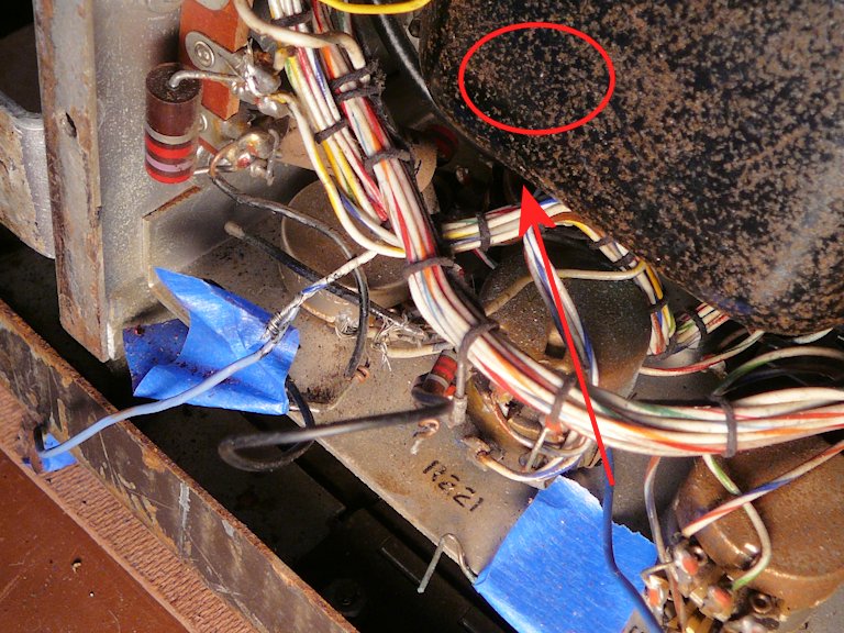
Along the bottom edge of the chassis is a row of controls, including R3, which
we saw earlier, and R227/R221/R222, seen in this photo. There is a second row of
controls, including the screen purity control, R241, which in this case lies
out of sight under the power transformer. I drew a red arrow and oval to show its
approximate position.
Various wires have been ripped loose from these controls. Among them I
found the far end of a lead that was left floating loose near the choke L34.
Restoring connections to the screen purity control will require pulling the
power transformer, or at least loosening its connections enough to move it
out of the way, a chore that I don't relish. But that's for another day.
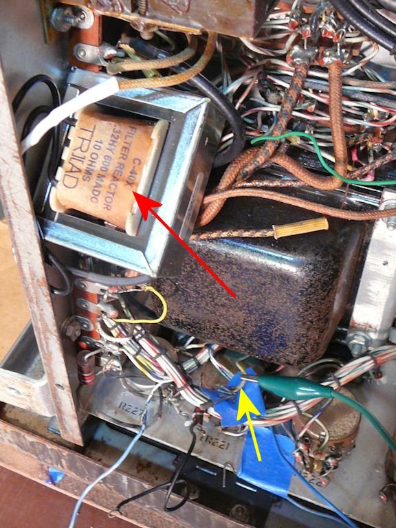
In the meantime, at least I can replace the missing choke. The next photo
shows the new one all wired up. It is a
Triad C-40X,
ordered from Mouser Electronics.
The bottom of the big black power transformer blocks access to R241, hidden
underneath. The red arrow shows the new choke and the yellow one
shows the wire from the choke that I must reconnect to R241.
Stay Tuned
More to come. This restoration is incomplete. I'll update this article
as the project unfolds.
|