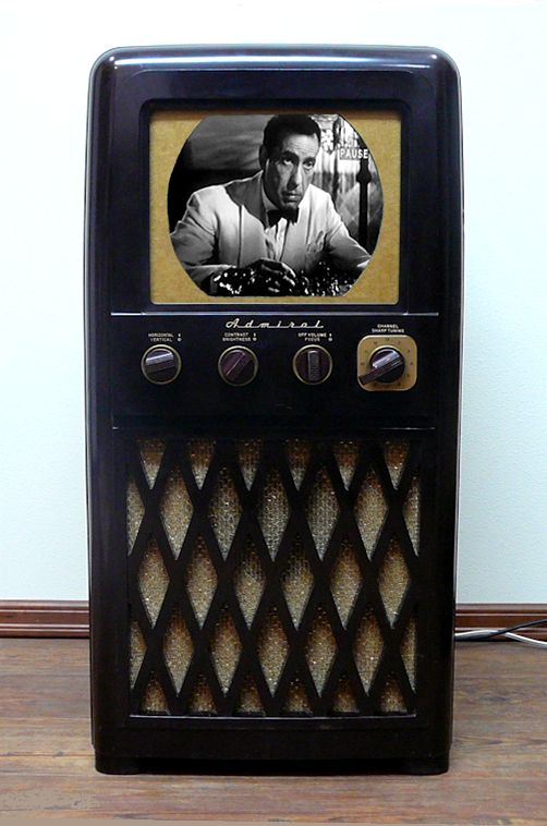
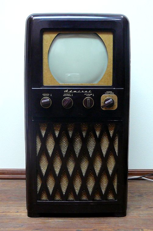
Admiral Model 24A12 Television (1948)


This Admiral model 24A12 TV from 1948 is highly collectible. Its Bakelite cabinet
and gold grille cloth make a bold design statement; the electronics are well designed,
making it a good performer after restoration; and it's petite for a console television,
an important factor for a collectors with limited space.
Description
Model 24A12 is one of many popular Admirals from the 1940s and 1950s. Its
20A1 chassis is nearly identical to the 20B1 chassis in the
Model 24C15 that I restored last year.
The difference is that this TV uses a 10-inch picture tube and the other has a
12-inch tube.
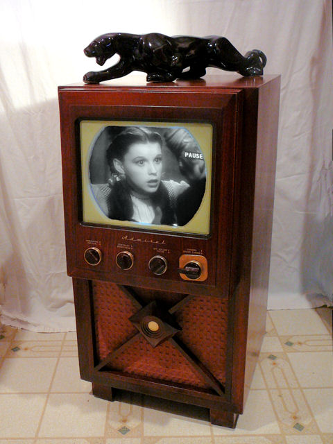
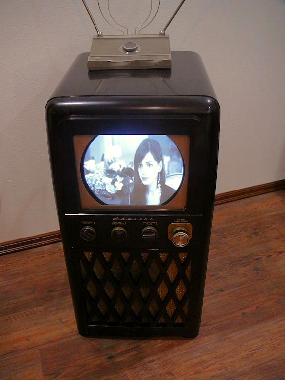
Here are photos of the 24A12 and 24C15 after restoration. The scale of the photos is
different, but you should be able to see that the 24C15 has a larger screen. (Notice where
the knobs lie in relation to the screen edges.)
Both models are covered in the same Rider's service
manual, available from the Early Television Foundation schematic
archive.
Click on the following thumbnail to view the 24-megabyte manual in PDF format;
to save it, right-click on the thumbnail and choose Save Target As.
This television uses 24 tubes in two chassis. The main chassis has 20 tubes:
| Tube |
Type |
Function |
| V101 |
6AG5 |
RF Amplifier |
| V102 |
6J6 |
Ratio Detector |
| V201 |
6AU6 |
1st Audio IF Amplifier |
| V202 |
6AU6 |
2nd Audio IF Amplifier |
| V203 |
6AL5 |
Ratio Detector |
| V301 |
6AU6 |
1st Video IF Amplifier |
| V302 |
6AU6 |
2nd Video IF Amplifier |
| V303 |
6AU6 |
3rd Video IF Amplifier |
| V304 |
6AL5 |
Video Detector |
| V305 |
6AU6 |
Automatic Gain Control |
| V306 |
6AC7 |
Video Amplifier |
| V307 |
10BP4 |
Picture Tube |
| V401 |
6SN7GT |
Vert. Oscillator / Sync Inverter |
| V402 |
6K6GT |
Vertical Output |
| V403 |
12AU7 |
Sync Separator / Clipper |
| V404 |
6AL5 |
Horiz. Sync Discriminator |
| V405 |
6SN7GT |
Horizontal Oscillator |
| V406 |
6BG6G |
Horizontal Output |
| V407 |
1B3GT |
High Voltage Rectifier |
| V408 |
6W4GT |
Damper |
The four-tube power/audio amplifier chassis is mounted in the base of the cabinet:
| Tube |
Type |
Function |
| V501 |
6SQ7 |
Audio Amplifier |
| V502 |
6V6GT |
Audio Output |
| V503 |
6X5GT |
Low Voltage Rectifier |
| V504 |
5U4G |
High Voltage Rectifier |
The electronic design is conventional, with split-sound audio and
automatic gain control (AGC). The 10BP4 picture tube was the most
common CRT in the late 1940s. In my
Television Gallery you can see six
other early TVs with 10-inch tubes, made by Capehart-Farnsworth,
Hallicrafters, RCA, and Westinghouse.
Admiral produced seven TVs with Bakelite console cabinets. In 1948 and 1949, models
20X122
and 24A12 had round 10-inch picture tubes. These 10-inch sets are easily distinguished by
the diagonal pattern of their speaker grilles.
The other Bakelite consoles have a rectangular grille pattern and larger picture tubes. Model
22X12
from 1949 had a round 12-inch CRT.
Four later TVs employed rectangular tubes:
24R12 (14-inch),
26R12 (16-inch),
and 27K12 and 27M12 (17-inch).
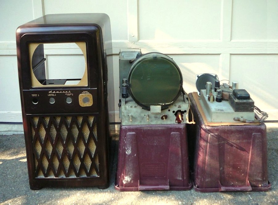
Finding the 24A12
This television came from Cle Elum, Washington.
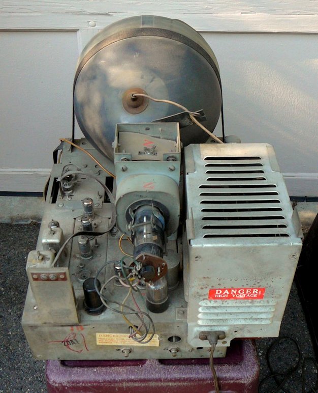
The next photo shows the TV as found. To the right of
the cabinet are the main chassis and the smaller power/audio chassis.
Cle Elum is only a 90-minute drive from here, but I removed the main chassis
before bringing this TV home. Although Bakelite is a strong material, the weight
of the chassis might crack or break the cabinet in transit.
If you buy one of these at long distance and need to ship it, I strongly recommend
that you have the seller remove both of the chassis and ship the television in three
containers. Many Bakelite cabinets have been wrecked by
careless shipping. No matter how well you protect the television against damage
from the outside, the internal weight of its chassis can break the cabinet. In this
forum
discussion
you can see a sad photo of a ruined cabinet.
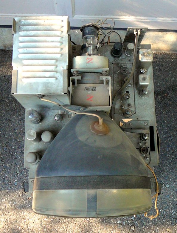
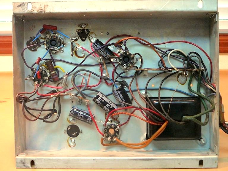
The next three photos show the main chassis. Apart from the usual dust, it's
complete and unmolested. Even the high voltage compartment isn't too dirty inside.

The set is missing a few tubes, but I can supply those from my stash of spares. When I
found this TV, it was missing the cover for its high voltage cage; I obtained a replacement
from a fellow collector a few weeks later. I also bought a few other missing parts: a
channel selector knob and some tube shields.
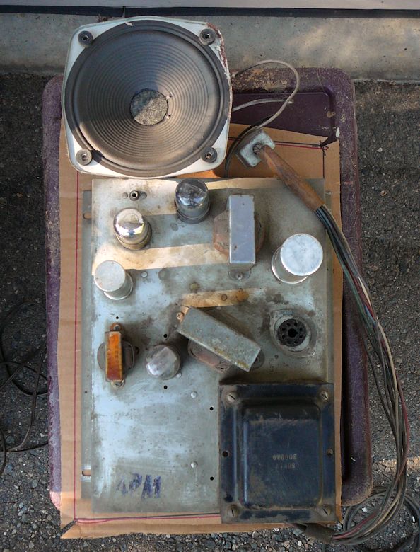
The small power/audio chassis is much simpler than the main chassis. With few components and
plenty of elbow room, it should be a snap to restore.
First Steps
As outlined in my article First Steps in Restoration,
I began by testing and cleaning all of the tubes' pins and sockets, along with all of the
set's potentiometers and switches.
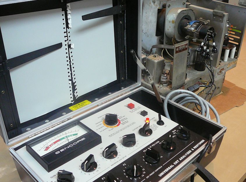
The picture tube came up nicely on the emission scale after sitting on my Sencore CR70 tester for a few minutes.

The remaining small tubes all tested good, so I only needed to clean their pins and sockets.
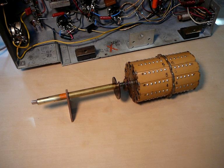
I gave the tuner barrel an initial cleaning with isopropyl alcohol (rubbing alcohol) and a
paper towel. Note the cleaned and uncleaned portions in this photo:
No other chemicals were needed to clean the tuner contacts. Never clean them with sandpaper or
other abrasives.
The screen cover was missing and someone had taped this dark piece of plastic over the front of the CRT.
I'll make a new screen cover later.

Replacing Electrolytic Capacitors
As always, I began with the TV's power supply, most importantly its electrolytic capacitors.
Since I have covered capacitor replacement in dozens of articles,
I won't bore you with too many details.
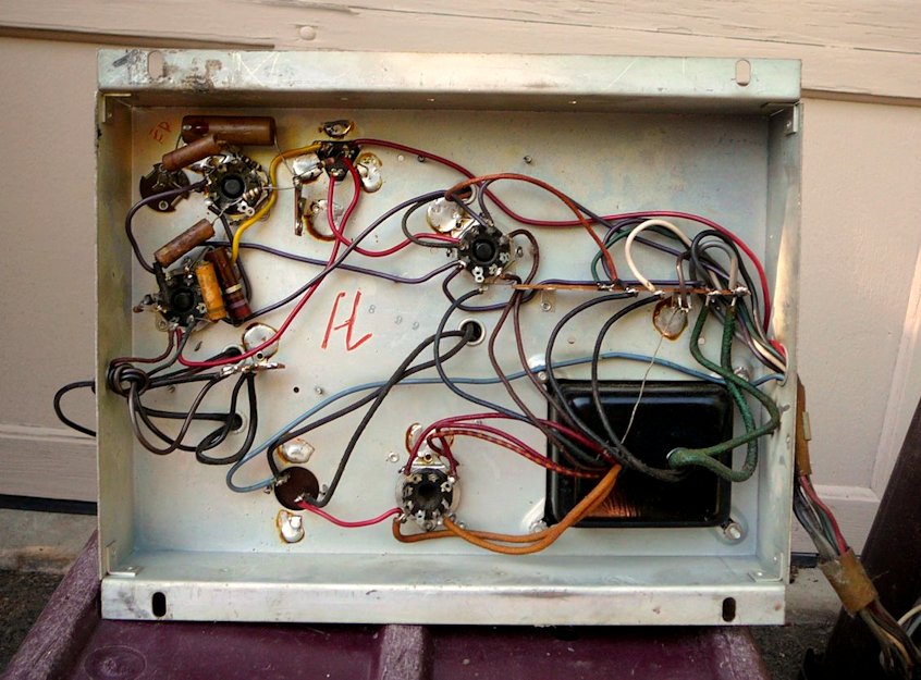
Here is the power/audio chassis before and after recapping:

There was plenty of empty space, so I put the new electrolytics underneath rather
than conceal them in their original cans. I attached two little terminal boards by securing them
onto the stubs of existing screws that projected under the chassis.

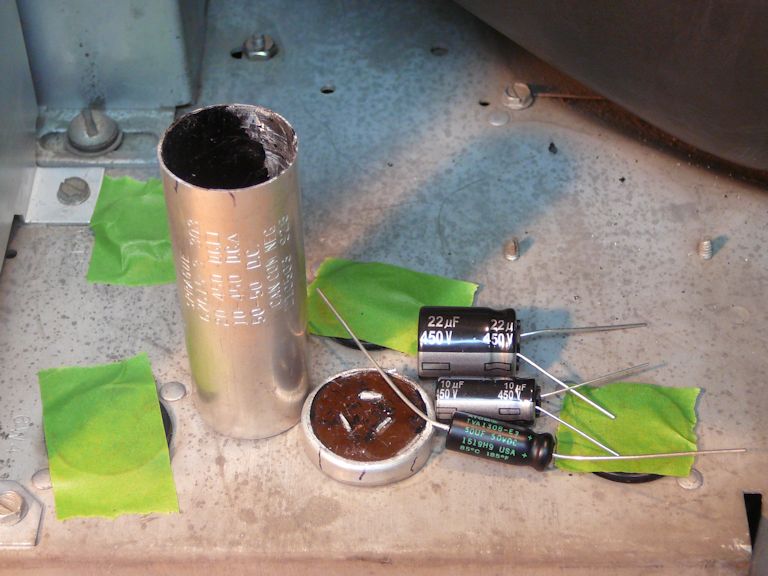
On the main chassis, this can was a little too small to contain all three replacements, so I
put the biggest cap inside the can and wired the two smaller ones underneath.

First Power
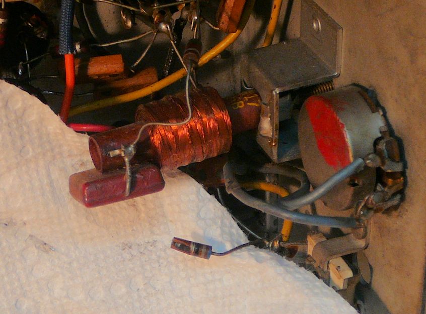
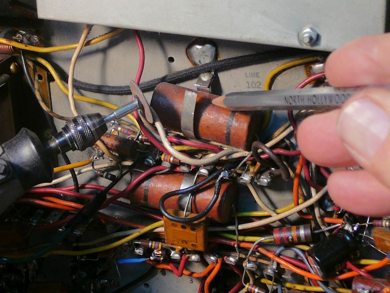
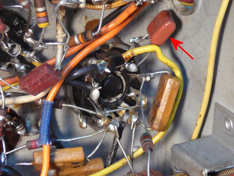
My initial inspection had uncovered a cracked resistor connected to the horizontal drive control.
When I bent its lead for a closer look, I saw that it had broken completely in half.


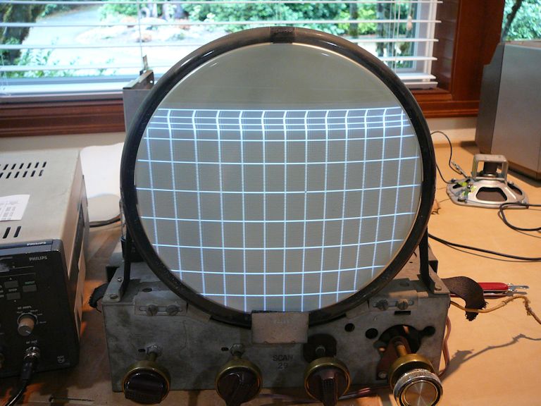
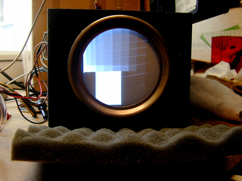
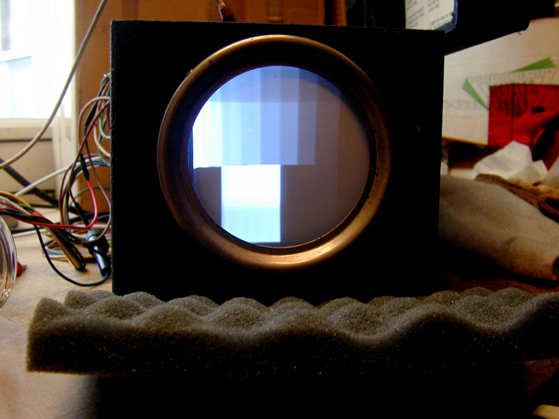
After replacing that resistor, and with new electrolytics in place, I powered up the TV for the first time, gradually increasing
the line voltage with a variac and watching for excessive current draw. After a little adjusting
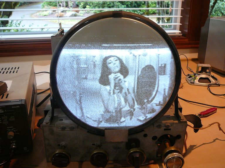
of the ion trap magnet on the picture tube neck, I saw the following images. The first is
a crosshatch pattern from my Philips pattern generator and the second is a scene from Cleopatra,
received over a rabbit-ear antenna from my home TV transmitter:


It's encouraging to see the TV produce a coherent image with only minimal restoration, but
of course this project is far from complete. The vertical
linearity is defective—notice how the top portion of the image is compressed—and we have
poor contrast and focus. The audio only amounts to some faint hissing and buzzing. This is
not unusual behavior for a TV that still contains loads of old paper capacitors.
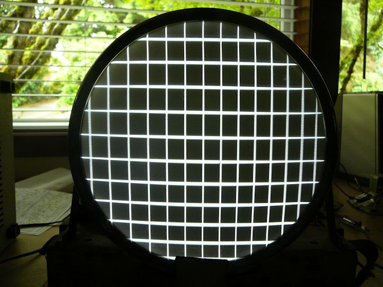
Replacing Paper Capacitors
I went on to replace the small capacitors in the vertical and horizontal circuits, along with
a few resistors that tested out of tolerance. The next photo shows better screen geometry:

A couple of large paper capacitors are fastened to the chassis with metal straps. If you slice
the strap with a Dremel tool, it's easy to remove the cap and replace it with a (much smaller) new one.

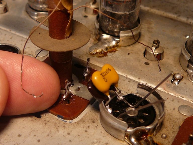
Don't overlook this little paper cap buried behind other components near the horizontal
oscillator tube:


The old capacitor was mounted so that its leads circled around part of the tube socket.
The new cap was so much smaller that I could mount it with shorter leads, taking advantage
of a closer ground lug on the same socket.
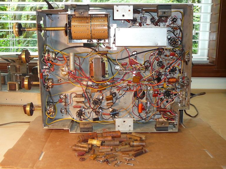
In addition to paper capacitors, I replaced a few more resistors and a handful of mica capacitors
in the vertical and horizontal sections, where precise values are important and certain caps take
a beating. Here is the underside of the chassis and a pile of replaced components:
Tuner Cleaning
The Admiral 24A12 has a sturdy turret-style tuner. As noted earlier, I gave the contacts on the
tuner barrel an initial cleaning with isopropyl alcohol.
Cleaning the buttons on the barrel is often all that a turret tuner needs. In this case, the tuner
was still a little sketchy. When changing channels, sometimes I could hear crackling and see
noise on the screen. Occasionally I needed to rock the tuner to tune a channel completely.
The buttons on the barrel make contact with a row of buttons inside the tuner shield.
I'll remove the barrel to clean those.

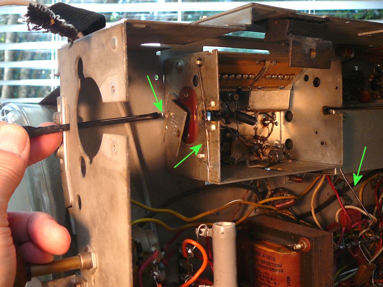
Removing and reinstalling the barrel is a little tricky, so I don't recommend doing this unless you
have a reason. Its axle is held inside the tuner shield with two stout pieces of spring wire that are
bent to fit tightly inside clips. You also need to loosen a bracket whose mounting bolt can only be accessed
through a slot using a long, thin screwdriver.

Whether or not you remove the barrel, it's a good idea to lightly lubricate the contacts
after cleaning. I applied a very light coat of Vaseline (petroleum jelly), a recommendation that I
got from an old-time repairman.
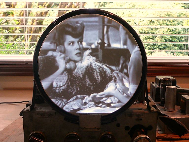
An Improved Image!
At this stage of the project, the video performance was very nice. Here's a candid
screen shot of a cable movie playing through my in-house transmitter:
Eliminating Retrace Lines
Like many TVs of this vintage, the 24A12 shows several thin slanting lines across the screen when you turn up the
brightness control beyond a certain point. (This may be in response to a weak signal, a weak picture tube, or simply
because the viewer wants a brighter picture.) You can eliminate these retrace lines by adding two little
parts: a resistor and capacitor.
The lines appear because the TV lacks a
circuit to blank the video scanning beam during the TV's vertical retrace interval, when the position of
the beam is returned from one side of the screen to the other. These photos show the telltale lines when I
was experimenting with a retrace blanking circuit for my Philco 49-1240.


This issue was so common that manufacturers recommended fixes in their service literature. The circuit that I added to
this Admiral 24A12 (20A1 chassis) is described on page 1 of the book
TV Manufacturers' Receiver Trouble Cures, volume 1,
available from the Early Television Foundation website.
The instructions refer to part numbers in the Riders service manual.
The next photo shows the new parts: a .047-mfd capacitor, 270K resistor, and a little terminal board
to allow for a tidy installation:

The connection points are located far apart in the printed schematic, although they are located
close together in the physical chassis. These schematic snippets highlight the connection points:
the junction of R325A (brightness control) and C315, and
the junction of C405 and R408 near the vertical oscillator tube:


This photo shows the same connection points in the chassis. At upper left is the brightness control's
center terminal; farther down is resistor R408:

And here is the blanking circuit installed on its terminal board.

Notice how the yellow wire (from pin 2 of the CRT) has been moved down from the brightness control's center
terminal to connect to the new 270K resistor on the terminal board. I also added a short blue wire to
connect the new .047-mfd capacitor to the 8.2K resistor (R408) on a nearby terminal.
Not every old TV needs this modification, but if your set displays those annoying retrace lines,
it's usually a simple fix. Since it was recommended by the manufacturer during this model's
original service life, you needn't worry that you're doing something unauthentic. Vintage TVs are not
all identical, so the remedy will vary for different circuits; consult a source like
TV Manufacturers' Receiver Trouble Cures
to make sure you're on the right track.
Replacing Mica Capacitors in Audio Transformers
Now the picture looked good, but the sound was pathetic, and routine debugging didn't
unveil any obvious culprits in the audio section. The tubes and tube-socket connections were fine; the resistors
all tested within normal tolerances; and these circuits don't use any paper capacitors, only reliable ceramics.
I worked through the audio alignment procedure, but the signal was very weak and
I couldn't find strong peaks when adjusting the transformers.
Having faced the same problem in my
Admiral 24C15 console,
I decided to replace the two little mica capacitors inside the audio transformers.
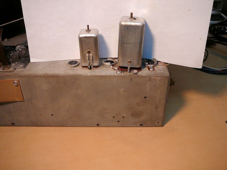
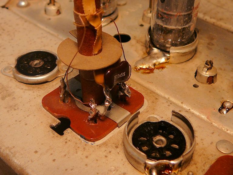
In that earlier project, I removed the transformers completely. This time around, I realized that I could
simply remove the cans and replace the little caps while leaving the transformers (and
all of their other connections) undisturbed. Below are two views of the transformers and their cans:


The cans are secured at their tops and bottoms. You loosen the tops of the transformers by squeezing
a pair of tiny tabs on their domes. The can bottoms may be secured with either clips or nuts. In this case, the leftmost
can was secured with spring clips, which you release from above by squeezing with a thin plier. The
rightmost can was secured with two nuts under the chassis.
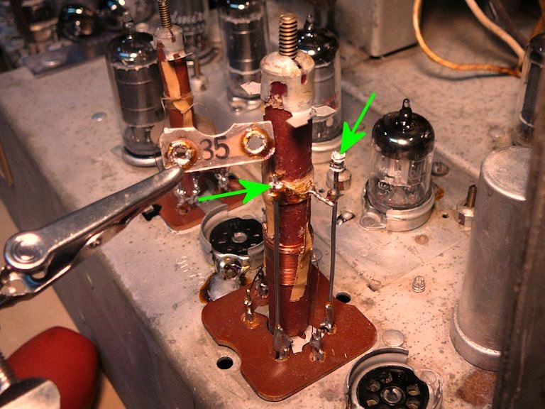
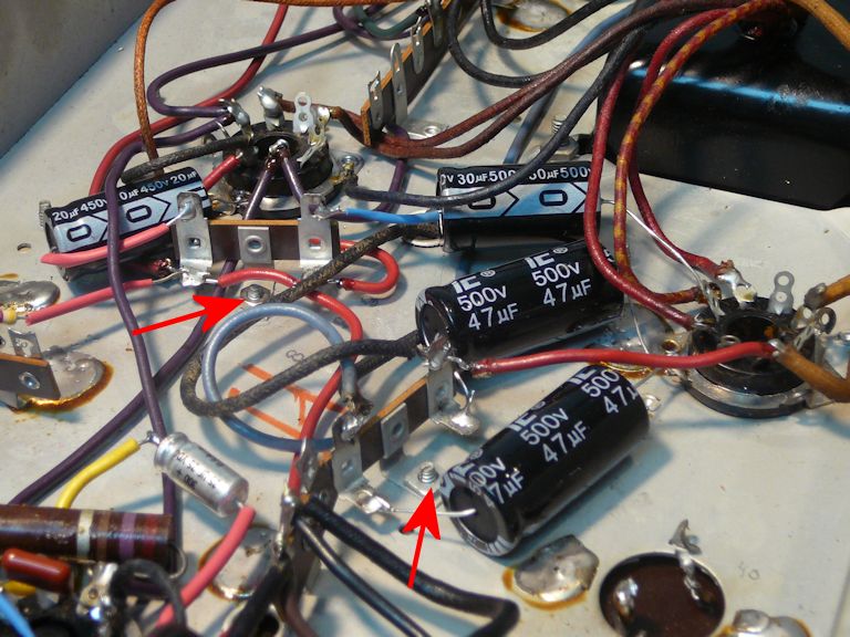
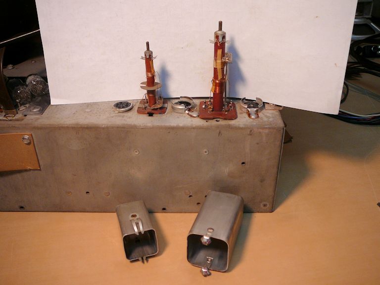
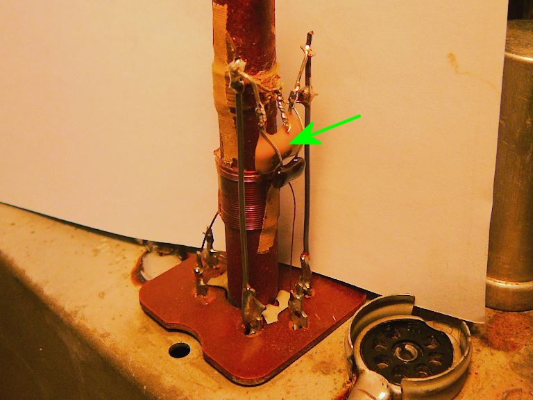
The next photo shows the uncovered transformers, with arrows pointing to the little bare
mica capacitors:

Each capacitor has two hollow rivets whose holes slip over little posts on the transformer frame.
Thin wires from the transformer coils were wound around the posts before soldering, so replacing the caps
is a delicate process.
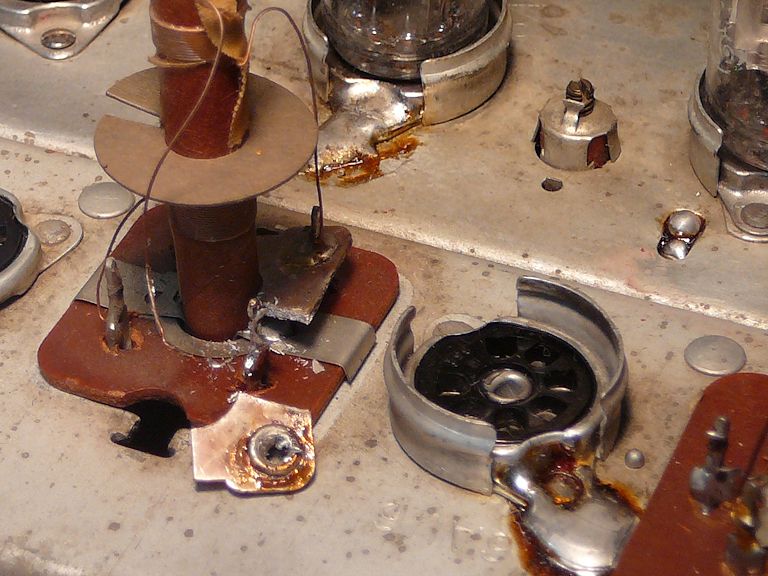
In this photo, I have snipped the cap in half and unsoldered one of the pieces, sliding it up and away from the post:

After removing the cap fragment, you can unsolder and (carefully!) unwind the connecting wire.
In the next photo, both halves have been removed and the wires are free. My replacement capacitor
is sitting in the nearby tube socket, ready for installation. To get the desired value (30 pf), I soldered
two new mica caps in parallel.

Here's the new cap soldered in place. I rewound the tiny wires onto the posts using a pair of tweezers.

The other cap was easier to replace. Mounted on tall posts, it simply lifted off after unsoldering,
without disturbing the connecting wires. The second photo shows the new cap in place, hanging down
from the tops of the posts; once again, I wired two caps in parallel to get the desired value (35 pf).

After I replaced those caps and reinstalled the cans, it was a snap to align the audio section and
get clear, strong sound.
If you're not comfortable with such delicate soldering, you could alternatively snip the old capacitor
in half and then wire the new one to the transformer terminals under the chassis. The old
capacitor fragments can remain in place, as long as you snip out enough to leave a complete
air gap between them.
So, there are three alternate approaches for replacing these little mica caps:
- Remove the transformers completely, as I did in a previous project.
- Remove only the cans and replace the old caps in situ, as I did this time.
- Remove the cans, snip the old caps, and wire new caps onto the terminals under the chassis.
To Replace or Not to Replace?
Don't assume that you should always replace the capacitors inside transformer cans. In restoring
a few dozen vintage TVs, I have only needed to do this twice, for Admirals using chassis
20A1 or 20B1, and only for the audio transformers, not the video IF transformers.
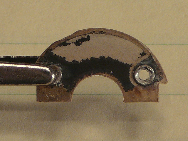
Mica capacitors are generally quite reliable, but this sort of naked cap—basically
a chip of uninsulated mica with two rivets—is prone to "silver mica disease,"
a problem commonly found in certain 1950s radios. As shown in this photo from my
24C15 article, silver oxide can migrate between
the capacitor terminals, changing the capacitance or even creating a short circuit:

Before resorting to this procedure, you should eliminate other, more obvious trouble sources
in the audio circuits, such as defective tubes or intermittent tube-socket connections, resistors
that are burned or out of tolerance, or simple misalignment. I went
this route only after checking out the rest of the audio section and finding that an alignment
couldn't improve its performance. My 24C15 article
has more details about audio alignment.
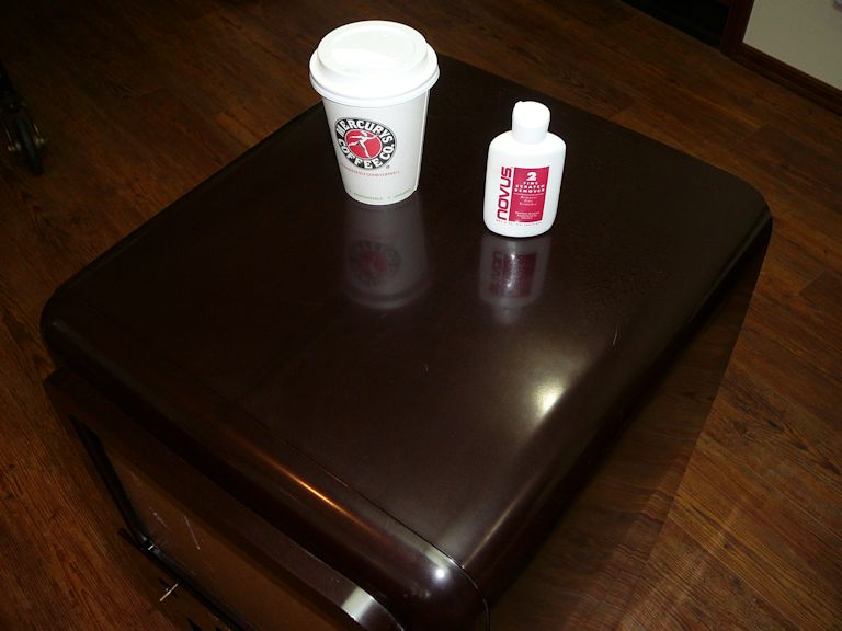
Cabinet Cleaning and Polishing
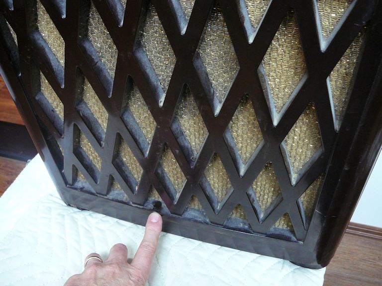
Now that I had good video and audio, I turned my attention to the cabinet. It took a while to remove the
caked dust from this complex grille.

Cleaning the cabinet didn't require anything exotic, just water, paper towels, a little Windex, and
a lot of patience. After it was clean, I polished it with Novus Plastic #2.

Polishing gave the cabinet an even color and it removed minor blemishes. Some people try to give Bakelite
cabinets a mirror-like sheen, but I didn't attempt to do that. In this condition, the cabinet looks
very presentable and without blemishes that call attention to themselves—like a well-cared for original,
in other words.
Replacing the Screen Cover
This TV was missing the clear screen cover and mask that go in front of the picture tube.
A previous owner had taped a circle of dark plastic over the CRT. Inside the cabinet, I
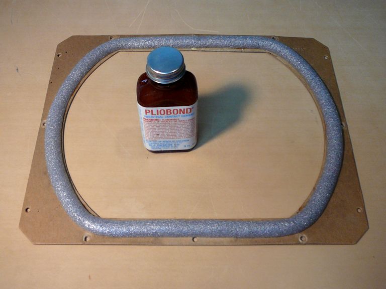
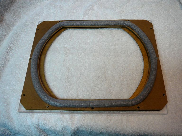
found a piece of cardboard with crumbling remnants of a foam CRT gasket.

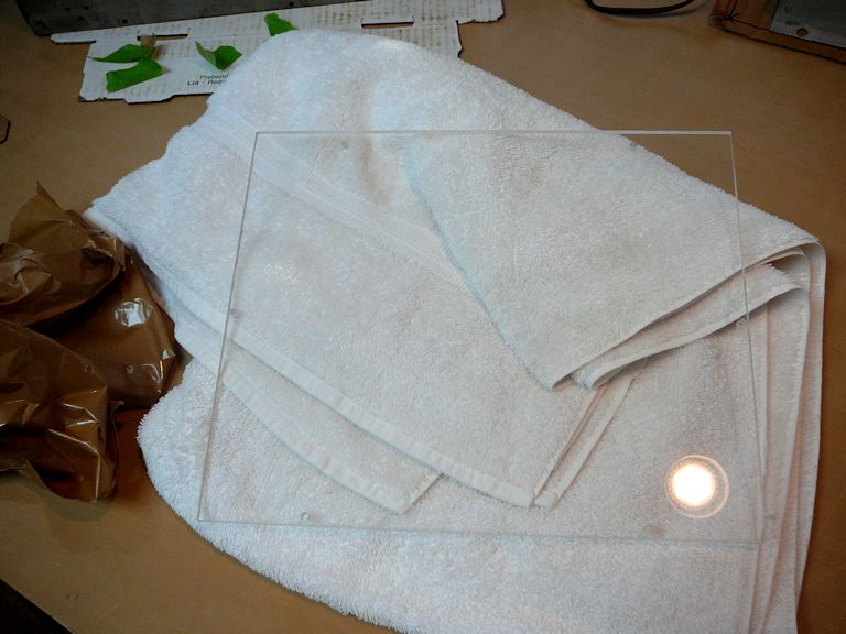
Using the old cardboard as a template, I cut and drilled a new piece of clear Lucite to form
a new screen cover.


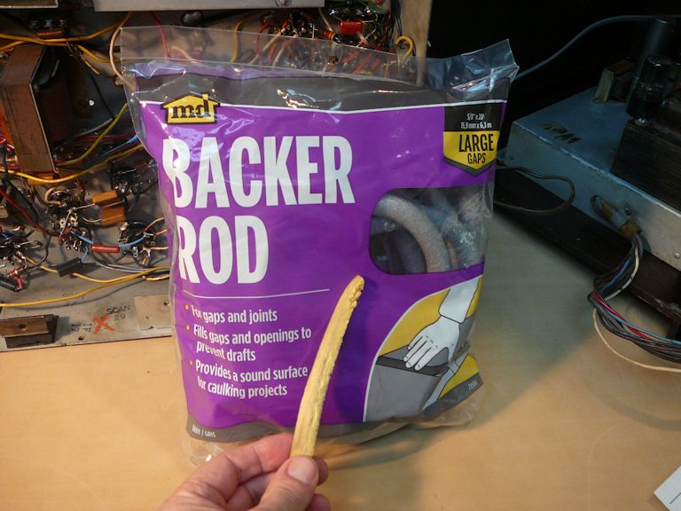
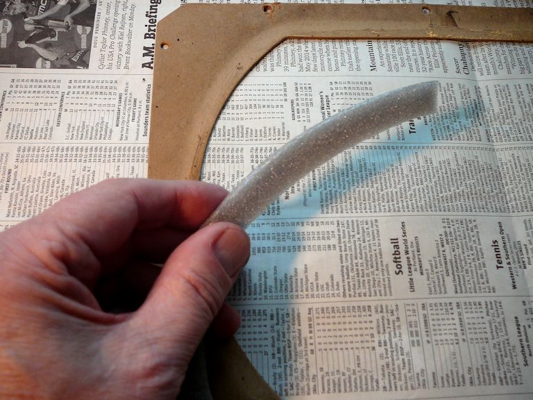
I replaced the old crumbling gasket with a piece made of new foam insulation:


When I installed my new screen cover, I found that the old cardboard mask wasn't wide
enough to cover the sides of the CRT.
Rats! It hadn't occurred to me that the cardboard piece wouldn't be the right size to serve as a mask.
When I inquired in the VideoKarma TV forum, I discovered that
this Admiral model shipped with two different styles of screen cover.
One style of cover is the same as the one in my other Admiral console (a 24C15).
It's a rather elaborate item, cast in heavy Lucite with a reverse-painted mask:

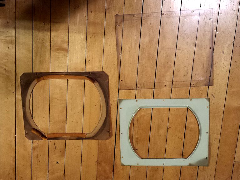
Another cover—possibly a cheaper, late-production version—consisted
of three parts, as shown in this photo from fellow collector Bob Andersen:

Of those three parts, only the cardboard piece was present in my set. Somewhere along the
line, an owner lost (or broke and discarded) the plastic mask and the clear cover, replacing
them with a dark piece of flexible plastic.
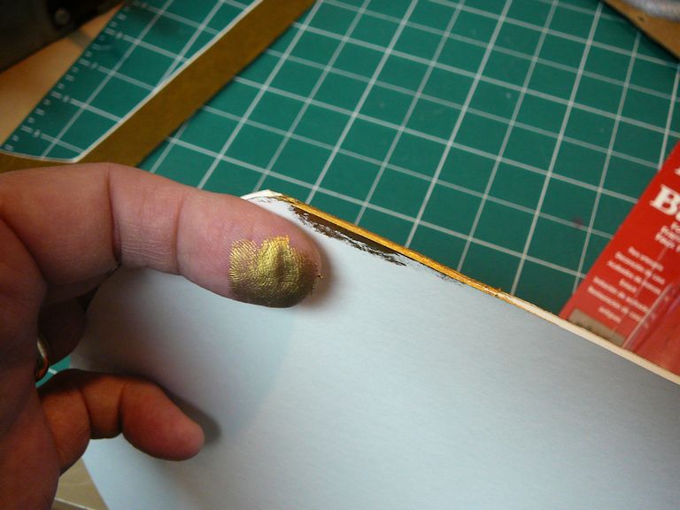
To replace the mask, I bought a piece of gold matte board at a framing shop and cut
it to size. Cutting the opening cleanly and evenly was harder than I expected, but
at last it was done—except that the cut edge was a distracting white color. I rummaged around and
found a tube of Rub 'n Buff, which made a good color match for the edges.


In this photo I placed the old cardboard atop the new mask to show the difference in size. I
kept the height the same and simply brought in the edges.

Here's the new screen cover in place. The mask is a good color match for the TV's brass knobs and
dark gold grille cloth.
Final Thoughts
With that final touch, I reinstalled the chassis and declared the project complete. Here's a photo of the 24A12 in action.
This little Admiral looks and sounds terrific, and I plan to keep it for a long time. If you only have
room for one small console TV, this set is a great choice.
|


