|

Creating a Home TV Transmitter
Now that TV broadcasts have gone digital, what is a
television collector to watch? Of course, you can hook up a DVD or VHS
tape player to watch recorded material on channel 3 or 4. You
can also use a converter to watch digital TV broadcasts on an analog set.
I prefer to watch television the "old fashioned way,"
with a rabbit ear antenna. I also like to use my vintage TVs
anywhere in the house, free of wired connections.
My solution is a home TV station. It covers the whole house and it can
be received by as many old TVs as I feel like powering up.
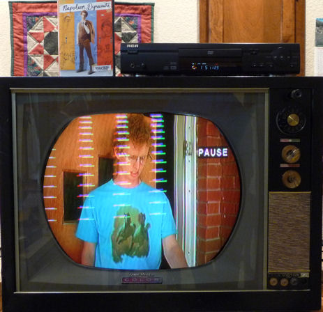
Let's Have a TV Party!
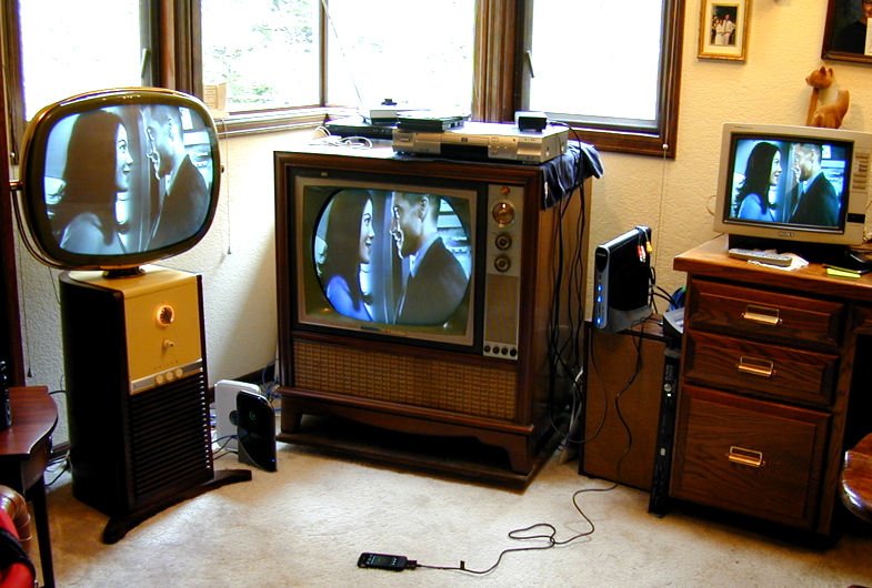
This impromptu "TV party" shows my transmitter in action.
The color set is my restored RCA CTC-11H.
The black and white set at lower right is my DuMont RA-103.
On top of the DuMont are two handheld TVs, the type which can only
receive through an antenna: a
Panasonic Travelvision
and a Sony Watchman.
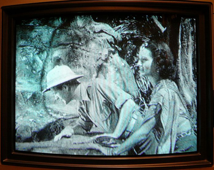
All four TVs are receiving through their antennas, from my home broadcasting
station on the other side of the house. The content is a live movie from
a satellite channel.
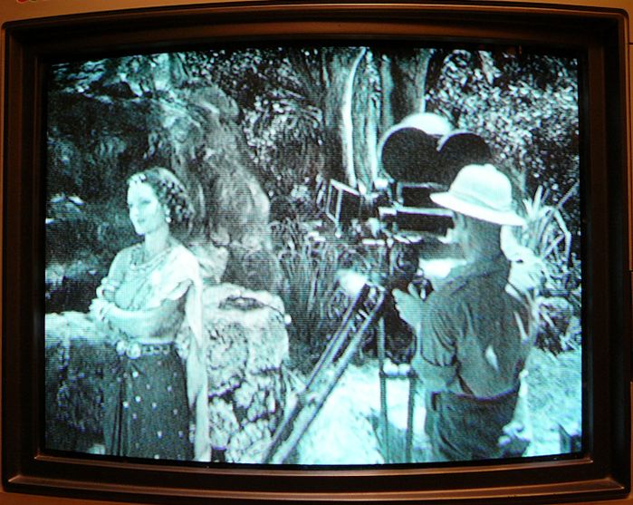
The second party features my Sharp 3LS36
mini color television along with the two handhelds. In this case, I hooked
up a DVD player to the transmitter.
Many mini portable TVs lack an external input, so if you collect handhelds, a home
transmitter offers the only way to use them at all.
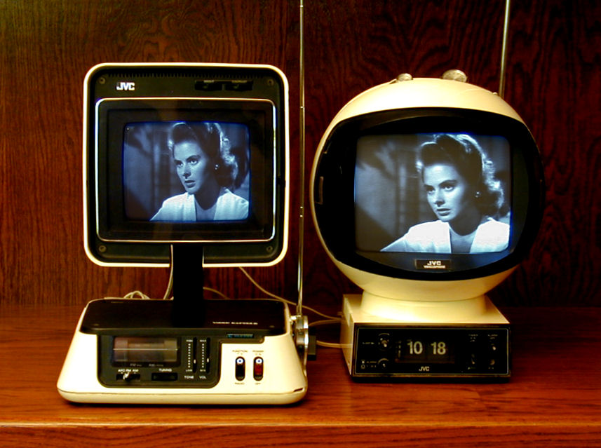
Here is a pair of space age JVC sets receiving a movie through their built-in
rod antennas.
Agile Modulator as Transmitter
Setting up this home station was easier than connecting
a typical DVD player. The heart is a device called an "agile modulator,"
specifically a Blonder-Tongue model AM60-550A.

I paid $26 for a surplus AM60-550A on eBay. It has ample power to reach throughout our house,
using a set of rabbit ears as the transmitting antenna.
Blonder-Tongue made a couple of different versions of this agile modulator: AM40 and AM60. The
first number (40 or 60) refers to the output power. The AM60 has a higher output, but the AM40 should
work if you're not trying to broadcast a great distance. The second number (450 or 550) refers to the
highest frequencies that the modulator can reach. Since those frequencies are far above the highest
frequency used in VHF television, either 450 or 550 will work just as well for this purpose.
Blonder-Tongue Owner's Manual
If you buy one of these modulators, it's worth getting the owner's manual, which
explains how to set the output controls. This allows you to get maximum transmitting
power without audio or video distortion.
The manual is free upon request from Blonder-Tongue.
Phone the service department at 1-800-523-6049 and tell them the stock number and model
number stamped on the rear panel. For example, mine is stock number 59414
and model number AM60-550A:

Connecting Your Video Source
Hooking up the transmitter couldn't be simpler. It has one input and one output.
For input, I often feed the transmitter from one of our cable TV
boxes. But you can use any source that produces standard audio/video output:
a DVD or VHS player, digital converter, video camera, and so on. Whatever
you choose will be broadcast to any TV in the house, on the channel you select.
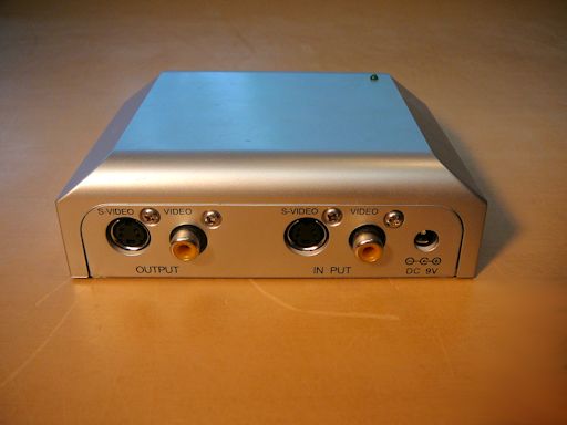
On the back of the Blonder-Tongue are jacks labeled AUDIO IN and VIDEO IN,
where you plug in the audio and video cables from your source device.

Note the short length of coaxial cable connecting the IF IN and IF OUT
connectors. My unit came with that cable. If yours lacks the cable,
you'll need to supply one. Nothing special is needed; use the same
coaxial cable as with any audio/video device.
The VIDEO IN jack is a coaxial F type. Many video sources will use cables with
phono (RCA) plugs. If needed, you can get an inexpensive
F-to-RCA adapter
from many electronic suppliers.
Broadcasting from an iPhone, Streaming from the Internet
If you have an iPhone or iPod, you can easily connect that to
your transmitter. All you need is a cable that produces composite
audio/video output. In this photo, my iPhone is feeding video
into the agile modulator, to be received by TVs all around the house.
A smartphone or similar Internet-enabled device vastly expands the
content that you can broadcast. Whatever you can stream from the Internet
or load onto your handheld player can be viewed on your vintage
TVs. I used to watch recorded tapes and DVDs on an old TV while working in
my shop. Now I can also watch movies or TV shows streaming from the Internet
via Netflix, Hulu, YouTube, you name it.
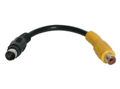
Broadcasting From Your Computer
If your computer has an S-video output jack, you can also plug in an inexpensive
S-video-to-composite adapter like this one, to send video to your transmitter.
You'll also need a cable that plugs into your computer's audio-out jack, with an
adapter to convert its stereo output to mono for the transmitter.
Thus equipped, you can transmit any video that you can view on your computer,
whether playing a DVD movie or streaming from the Internet. On my computer,
going to the Control Panel and choosing Connect To a Projector tells the
computer to enable the S-video output. The procedure may differ on your
computer.
Connecting Your Transmitter Antenna
Like every transmitter, the agile modulator needs an antenna. For a long time, I used this
old pair of rabbit ears. Any cheap antenna from a thrift store or flea market should work as well.
Notice the little matching transformer on the end of the antenna cable. This lets you plug it
into the transmitter's coaxial output jack. Many electronic suppliers sell antenna matching transformers
for a few bucks.

The next photo shows the RF OUT jack in back of the modulator, where
you will connect your antenna. To place your antenna a longer distance from
the modulator, extend it with an ordinary coaxial cable.
The type and length of your transmitting antenna is not critical
if your modulator is close to the TV. However, a bit of tuning may
improve your signal farther away.
It's easy to experiment if you are using rabbit ears to transmit and
receive. Simply shorten or extend the antennas for best reception on
the channel that you're using. Higher channels (such as 12)
need a shorter antenna length than lower ones (such as 3). A diagram
in a following section shows you the optimum length for any VHF channel.
Antenna orientation is important at longer distances. Move both of your antennas around
and find the orientation works best.
Choosing Your Broadcasting Channel
The agile modulator transmits on one channel at a time. You pick the
channel by setting little DIP switches in the front, following instructions
on a plastic card that slides out from the panel.


A DIP switch can be flipped up or down with a pencil point or small screwdriver
blade. Flip your switches to match the desired channel's diagram in the chart.
You can use any of the standard VHF channels 2-13.
It's prudent to check whether any stations are still broadcasting in your area.
Although many digital stations now use the UHF channels, a handful of
stations still use a VHF channel. You don't want to pick a channel that's
already in use, which might create a jumble of noisy interference.
To check for area stations, enter your address and zip code in the TV Fool
station
locator. You'll get a list of stations with their channels and
distance from your home.
When I checked, I found several VHF channels that are not used to broadcast anything in
my area. As long as I pick one of those empty channels, there is no chance of interference
with other signals.
Modern homes are full of devices that create electronic noise. I have found that the
higher VHF channels (7-13) are less affected by such interference than the lower ones (2-6). We'll discuss
this in more detail later in this article.
Building a Tuned Antenna for a Specific VHF Channel
If you're willing to commit to using the same channel all the time, you may be able to extend your
range a bit by making a dipole broadcasting antenna tuned to a specific channel. This
video tutorial by shango66 explains how.
In a nutshell, your antenna can be a simple dipole (two ordinary wires) connected to the agile modulator's
RF output with a coaxial cable. This antenna is a lot like the familiar FM radio dipole antenna. The type of
wire used for the dipoles is not critical. The coaxial cable is a standard 75-ohm cable, the same type
used to connect DVD players, etc.
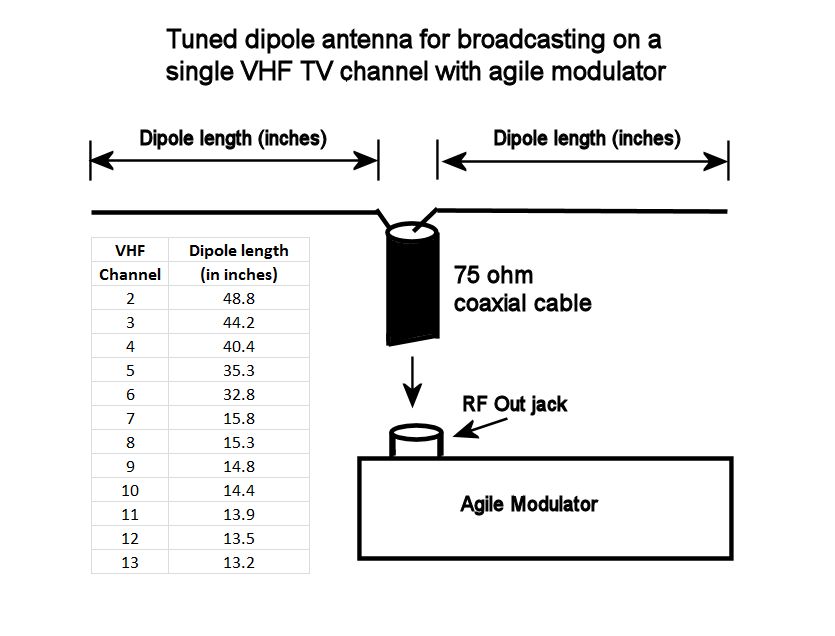
This diagram shows the correct dipole lengths for VHF channels 2-13:

For example, to build an antenna for broadcasting on channel 3, cut each dipole wire to 44.2 inches in length.
To build an antenna tuned for channel 12, cut each dipole wire to 13.5 inches, and so on.
Note that higher VHF channels use shorter antennas. In case you are curious, the formula for calculating the dipole
length in inches is: 468 divided by the channel's center frequency (in megahertz) divided by two (since you
want two dipole wires) multiplied by 12 (to convert feet to inches).
Solder one dipole wire to the center wire on a coaxial connector and the other dipole wire to the connector's
shield (outer) wire. Attach the antenna's coaxial cable and then connect the cable to the RF out jack on the agile modulator.
Hang your antenna as high as practical, with the arms (dipoles) spread out as in the diagram.
Antennas are directional, so experiment by turning your antenna one way or another in relation to your receiving TV.
Battling Electronic Noise
Just as when your vintage TV was new, its reception can be degraded by electronic noise (radio frequency interference, called RFI).
Nowadays our homes are full of potential interference sources, such as computer power supplies, "wall wart" AC adapters,
fluorescents, light dimmers, and so on. But interference can come from other quarters, as well. Let's look at them.
Hash from Power Supplies
The next photos show serious interference from my laptop's power supply.


When my computer was plugged in anywhere nearby, the video was full of
moving diagonal lines and the audio was drowned out by loud buzzing. The
TV was unwatchable!
As noted earlier, the higher VHF channels (7-13) are less susceptible to RFI than lower channels (2-6).
The bad interference showed up when I used channel 3. When I switched the modulator and television
from channel 3 to channel 12, the interference disappeared:


For this test, I chose a room at the farthest end of our house
from the transmitter, where the signal is faintest. If choosing a higher channel
eliminates RFI here, where the signal is weak and the RFI is strong, reception
will be even better in rooms closer to the transmitter.
I noticed the same improvement inside our garage, which sits even farther away.
When I used channel 3, the garage's fluorescent lights would essentially blank out
TV reception. The picture was a mess and the sound was unintelligible. After I
switched to channel 12, the video and audio cleared up dramatically.
Crawling Bands from 60-Hz Interference
Another type of power-supply interference appears as a faint horizontal band that moves slowly up or down the screen.
This symptom often indicates a filtering problem in a TV's power supply. Inadequate filtering allows a 60-Hz AC
signal to invade the RF circuits, and since this 60-Hz signal is out of sync with the 60-Hz signals in your TV's
vertical sweep circuits, an interference wave crawls up or down through the picture.
60-Hz "traveling waves" can also come from nearby devices, even if your TV is in tip-top shape.
When I first tried my agile modulator in my office, I noticed such a wave and tried various things to eliminate
it. The wave instantly disappeared I moved my wireless Internet router (with its "wall wart" AC
adapter) to a different outlet in the room.
New LED and compact fluorescent (CFL) bulbs can also create this interference.
Now my agile modulator is located in my workshop, and when I recently replaced the overhead floodlights
with energy-efficient LED bulbs, the familiar crawling wave reappeared. Fortunately, I didn't need to get rid of
all of my new bulbs: the interference went away when I unscrewed one bulb immediately above my modulator.
Distortion from VHS Tape Player
A VHS tape player can be the source of video distortion, creating horizontal smearing or
bending in the picture near the top of the screen. If you see a bent picture when
playing a VHS tape, try switching to a DVD player or other source. This distortion is
unavoidable when using certain combinations of VHS player and vintage TV; there is no cheap
or easy fix, other than avoiding VHS tapes or watching them on other TVs.
Interference from Copy Protection
Macro Vision copy protection can cause ugly interference in both the video and audio.
This photo shows Macro Vision interference (columns of colored lines) on my CTC-11A:

There's nothing wrong with the TV, as we saw in the earlier Shrek photo, and I simply wanted to
watch a DVD that I purchased, not copy it. The lines are caused by copy-protection data embedded in the video
signal. Such data didn't exist when the TV was built in 1961, and now it causes
garbage on the screen and buzzing in the speaker.
An inexpensive
video stabilizer like the one shown here will let you watch copy-protected DVDs and tapes on your vintage TV without such interference:

My no-name stabilizer cost about $30 and you simply plug it in line with your video cable, between the source and your modulator.
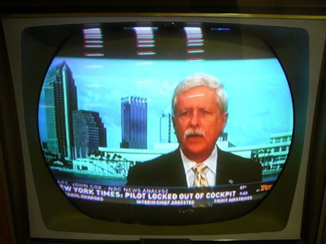
Interference from Cable TV
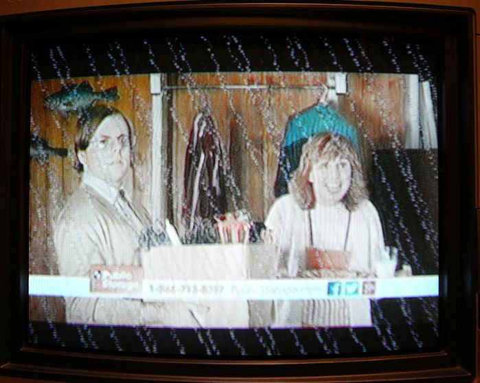
Even your cable TV system may produce interference. Look at this photo of a program
received through our cable box and broadcast through my home transmitter:

This interference is very similar to Macro Vision garbling, which pulses in and out. The telltale lines
fade in and out over a period of several seconds, accompanied by severe audio buzzing.
Cable TV doesn't use Macro Vision, so this was obviously something else. The interference appeared only
in a certain range of channels in our system, and it was visible in some of my restored
vintage TVs but not in others. I checked eight of my 1940s-1960s TVs, and
the interference appeared in about half of them, following no obvious pattern.
(Newer TVs in the house were immune to the interference.)
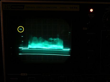
With the aid of an oscilloscope and advice from members of the VideoKarma
vintage TV forum, I finally identified the interfering signal in the TV broadcast. In this photo, the rogue
data is highlighted with a yellow circle.

With one eye on the scope and the other on the TV screen, I could see that the interference appeared and
disappeared precisely when the rogue pip moved up and down on the scope display. The distorted video was accompanied
by audio buzzing, as you can see and hear in this brief video clip:

There were various theories about the purpose of this signal. Perhaps it is closed-captioning data, or some other type of
encoded info. In any case, it's not part of the NTSC broadcasting standard that our vintage TVs were designed to follow.
You can read more about this investigation in the VideoKarma discussion.
The mysterious cable interference was easy to remove. I simply plugged my video stabilizer (see above) into the video line between
my cable box and my agile modulator.
Legal Transmission Limits
The Federal Communications Commission regulates broadcasts in the
radio and TV frequencies. I'm not good at deciphering legalese,
but as far as I can make out, a home transmitter's signal strength
must not exceed 100 milliwatts. My transmitter doesn't reach beyond our
property, and we live on three acres, so there's no danger of interfering with
neighbors' reception.
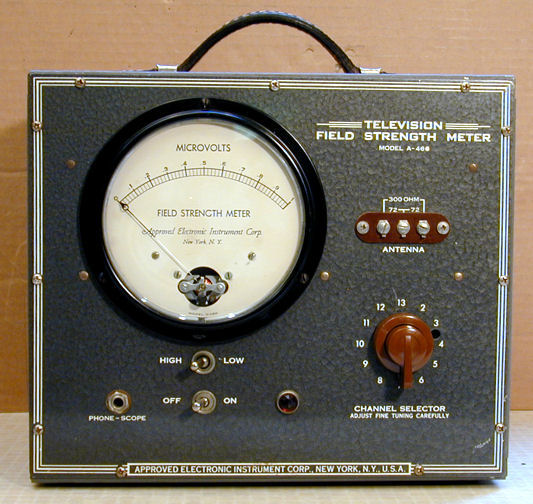
I happen to have an old TV field
strength meter, which was used years ago when servicemen installed
roof antennas in customers' homes.

I have no way to check this meter's accuracy. However,
it was fun to see its needle move when I turned on my home
transmitter.
A handheld TV like my Travelvision or Watchman makes a more
practical tester for a home broadcasting station. Just turn it on
and walk around the house! You'll find that antenna orientation is important
for the transmitter as well as the receiving TV.
A handheld TV (or even a handheld AM radio) is also handy for pinpointing sources of RF interference in your house.
Hold the TV or radio next to the device that you suspect of
creating interference. If the TV picture dissolves, or the radio
buzzes loudly, you may have located your culprit.
Handy For Restoration, Too!
I have found my home transmitter very useful when restoring vintage TVs
like the RCA CTC-11H and
DuMont RA-103 seen earlier.
Restoring an old television means playing it over and over,
to check this or that. In the old days, a serviceman could just connect
rabbit ears and tune in a local station. But nowadays there are
no local analog stations!
To test the TV on the workbench, you can connect a video player or digital
converter box, but that adds to the crowding and rat's nest of wires on your bench.
It also limits you to two channels: 3 or 4. What
about all the others? Does your TV work beautifully on, say, channel
11, but poorly on channel 4? Knowing that might save troubleshooting time.
When I'm working on a TV project, I leave the transmitter
on at all times and connect rabbit ears whenever it's time
to try my TV again. Quick and easy! By changing the transmitter's
channel, I can test the TV's performance on any channel.
Receiving a "real" over-the-air broadcast is also an
excellent performance test. Vintage televisions were
designed to operate in a world of often-weak broadcast signals.
You may get a much stronger signal when you connect a modern device like a DVD
player directly through a cable.
A too-strong signal can overload a sensitive old TV, causing the picture to
"bloom" and become unfocused or too-contrasty. If the video player is your
only source, you might wrongly think that your TV has a serious problem, when in fact
it's responding normally to an excessive signal.
If I'm receiving cable TV via my home transmitter, I know that I'm working with a
relatively pure signal and I won't have to waste time chasing false symptoms
caused by a modern device.
Servicing the Blonder-Tongue Modulator
The Blonder-Tongue agile modulator is an industrial-grade device,
designed to operate 24/7, year in and year out. Every device can
have problems, however.
After a couple of years of continuous use, my modulator developed a faint
horizontal band that moved slowly up the screen. This is 60-Hz AC
interference, as described earlier in this article.
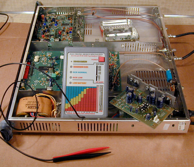
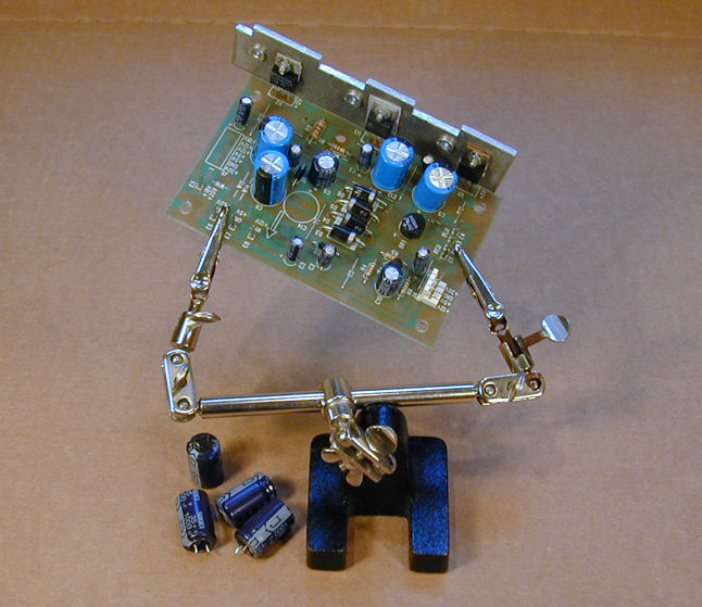
The power supply is not hard to service if you're comfortable with modern
PC boards. In the next photo, I have removed the small power supply board
and placed it atop the opened modulator. Also shown is the EDS Capacitor
Analyzer that I use to test low-voltage electrolytic capacitors.

It took only minutes to confirm that the four 1000-uf electrolytics in
my power supply were leaky. The next photo shows the board after I replaced them.
That cured the problem and my modulator has performed faithfully ever since.
This unit does get rather hot when running. If you're concerned about extending its life
(or simply saving energy), put it on a power strip and switch it off when you don't need it.
Be Creative!
Since I first published this article years ago, I have received email from people using this
"home transmitter" setup for more creative purposes, including art installations and
video displays for rock bands. If you come up with such a use, or you just want to show off
your results, feel free to send me an email.
This electronic construction project, including all descriptions, diagrams, photos, and the underlying electronic design, is published here for the noncommercial use of radio/TV hobbyists. You may print and reproduce these project instructions for your personal use. Commercial use of this material is strictly forbidden.
|