DuMont Model RA-103 Television/Radio (1948)


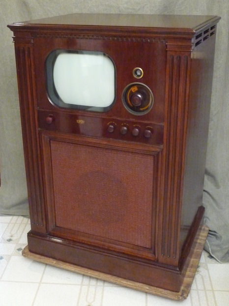
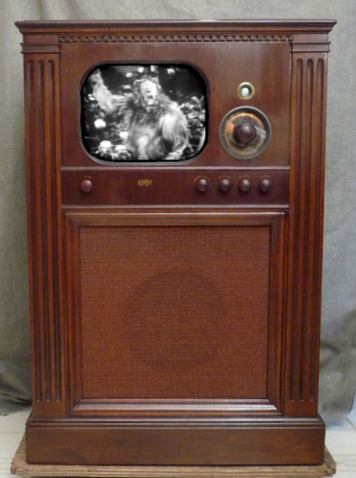
Here is a DuMont model RA-103 television from 1948, a 12-inch Teleset
in the Meadowbrook console cabinet. DuMont prided itself on quality and had
prices to match. This TV cost $525 when new, which equates to
thousands of 2014 dollars. It includes FM radio and
a "magic eye" tuner. With a generous 10-inch
speaker, this set has very nice audio for a 1940s television.
The moment I saw this classic set, I decided to give it a full
restoration. This involved a lot of work spread out over several
months.
RA-103 Design
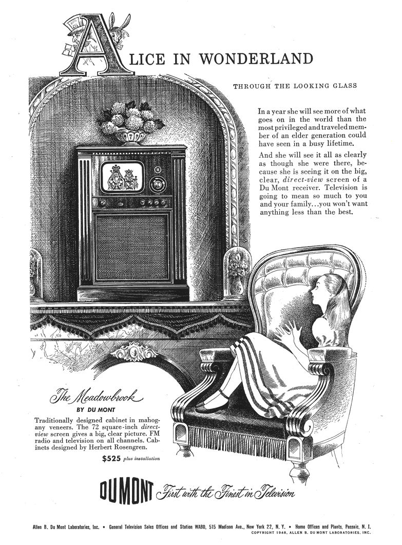
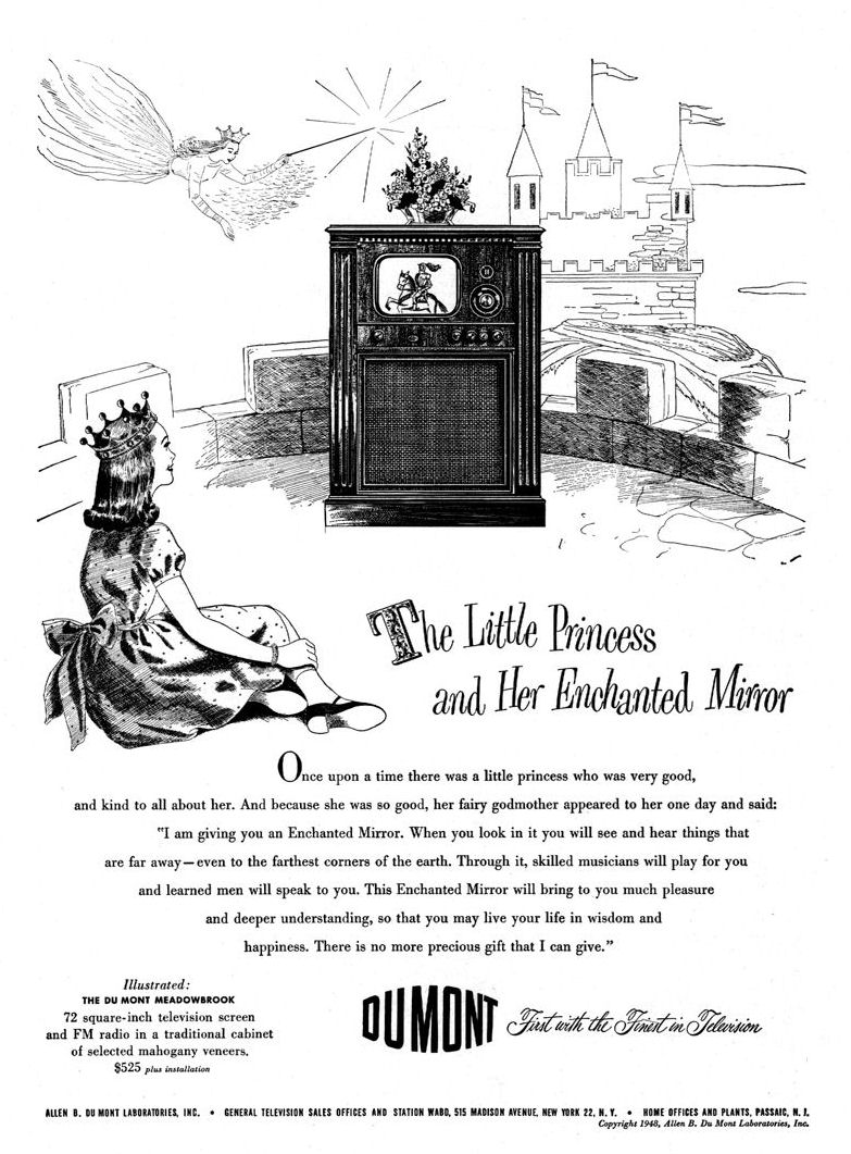
DuMont offered the RA-103 television in five cabinet styles. Mine is
the Meadowbrook. Click on these thumbnails to see Meadowbrook ads from the New
Yorker and National Geographic:

The Meadowbrook is described as "a traditionally designed cabinet
in mahogany finish and selected mahogany veneers. Unsurpassed television
on a 72 square-inch screen. FM radio."
Here's an ad from a New York City newspaper. It lists dozens of
DuMont dealers in the NYC area, including prestigious locations such as Steinway & Sons
in Manhattan:
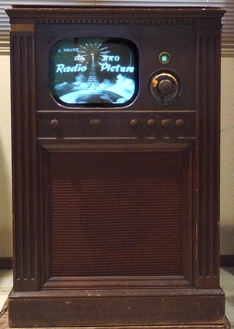
Here is my RA-103 Meadowbrook after restoration.
Other RA-103 cabinets include the Sutton, a blonde console shown
in the newspaper ad, and the Chatham,
a "doghouse" shaped tabletop favored by collectors due to
its compact size. The Savoy and Colony consoles added a phonograph and AM radio.
All of the RA-103 DuMonts receive FM radio.
My restored chassis appears below.
You can download the complete Riders and Sams service manuals
for this set at the Early Television Foundation
schematic
archive. I got a free copy of the Sams Photofact manual from my
local library. You can also buy it from Sams (folder
90-3).
Both manuals are worth using, since each contains some information not available
in the other. This article uses the Riders part numbers.
The RA-103 uses 25 tubes:
| Tube |
Type |
Function |
| V101 |
6J6 |
RF amplifier |
| V102 |
6AK5 |
Mixer |
| V103 |
6J6 |
VHF oscillator |
| V201 |
6AG5 |
1st video IF amplifier |
| V202 |
6AG5 |
2nd video IF amplifier |
| V203 |
6AG5 |
3rd video IF amplifier |
| V204 |
6AL5 |
Video det/DC rest/Sync takeoff |
| V205 |
6AC7 |
Video amplifier |
| V206 |
12JP4 |
Picture tube |
| V207 |
6AU6 |
1st audio IF amplifier |
| V208 |
6AU6 |
FM audio limiter |
| V209 |
6AL5 |
FM audio detector |
| V210 |
6SJ7 |
1st audio amplifier |
| V211 |
6V6GT/G |
Audio power amplifier |
| V212 |
6SN7GT |
Sync clip/Horiz saw generator |
| V213 |
6SJ7 |
Sync clipper |
| V214 |
6AL5 |
Sync discriminator |
| V215 |
6K6GT/G |
Horizontal oscillator |
| V216 |
6SN7GT |
Vert buffer/Vert saw generator |
| V217 |
6SN7GT |
Vert deflection amplifier |
| V218 |
5U4G |
Low voltage rectifier |
| V219 |
5U4G |
Low voltage rectifier |
| V220 |
6AC7 |
Reactance (horizontal sync) |
| V221 |
6BG6-G |
Horizontal deflection amplifier |
| V222 |
1B3-GT |
High voltage rectifier |
| V223 |
5V4G |
Horizontal damping |
| V224 |
6AL5 |
Time delay relay |
| V225 |
6AL7 |
Tuning indicator |
Like my 1946 RCA 630TS and others of the time,
this DuMont uses a "split sound" audio system. You can read more about that
design choice in the 630TS article.
The earliest Riders schematic shows a type 6U5 eye tube, but
my set and others use a 6AL7. It's unusual to see a magic eye tuning indicator
on a television. I have often joked that a TV already has a fantastic magic eye—that
big thing called a picture tube!
The eye tube can be used for both radio and TV tuning. The function selector
gives you the option to turn off the eye for television viewing.
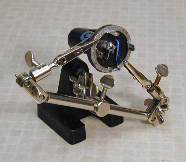
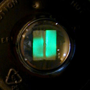
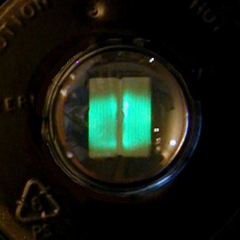
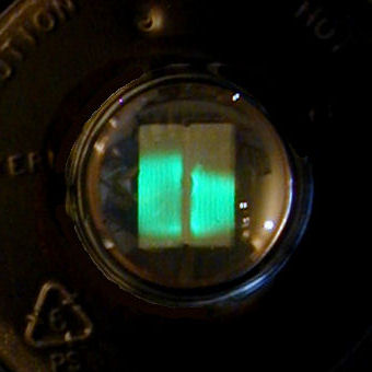
Most indicator tubes have a round green eye with a
dark "pie slice" that opens or closes as you tune in a station. The 6AL7
has two rectangular targets. One of them is always about 3/4 full and marks the
ideal tuning point. The other grows or shrinks as you tune.
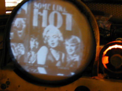
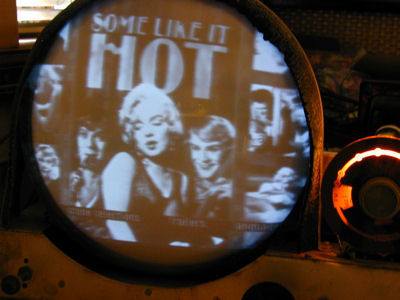
When the green targets
match, you have tuned the station exactly. The middle photo
shows the tuner centered on a station. The others show the eye when the tuner is
slightly off the mark, either above or below the ideal.


Including FM radio was no marketing gimmick, nor did it add extra
components or complexity to the TV. It arose naturally from their choice
of tuner: the famous Mallory InducTuner, which DuMont dubbed the Inputuner.
We'll learn more about the InducTuner later in this article.
Another notable feature is the time delay in the power supply.
This involves an electromechanical relay, a 6AL5 tube, and
a few other components. In the words of the DuMont service
manual:
The relay circuit has been designed so that the relay
is energized approximately ten seconds after the power is applied
to the television receiver. In this way all capacitors and other
components are protected from the high surge voltage which
otherwise would occur before the tubes heated up and started
to draw plate current.
Only DuMont would make such an investment to improve the television's
longevity. Most 1940s manufacturers simply ignored the surge issue.
Some later TVs, such as my 1958 Philco Predicta or
1961 CTC-11A, get
a soft startup thanks to an inexpensive thermistor in the
AC power line.
The RA-103 does not have an automatic gain control (AGC) circuit,
a topic that we'll investigate later.
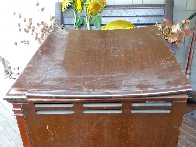
First Look
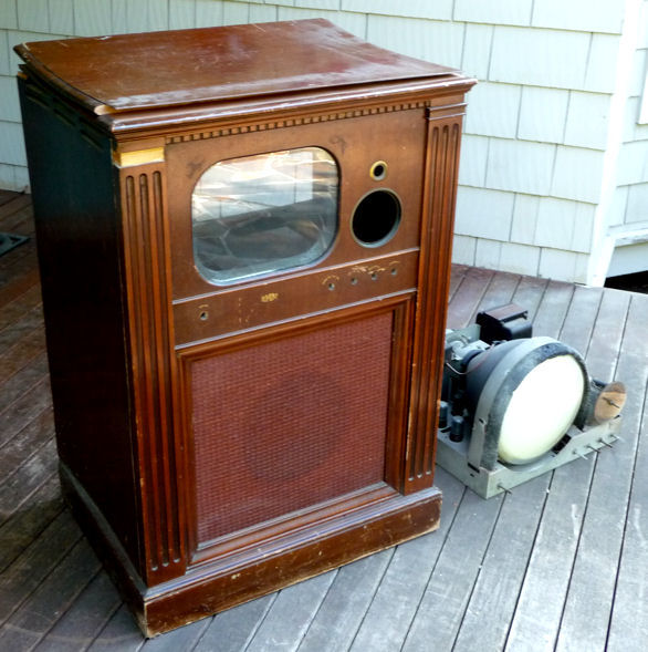
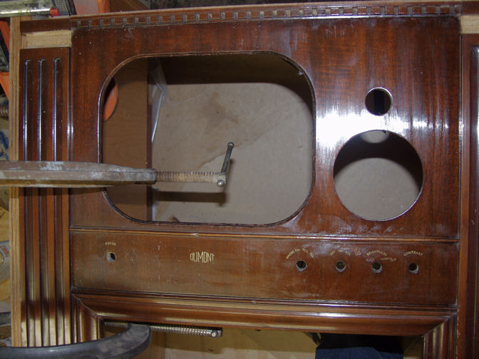
I bought my DuMont locally for $40. Here it is after unloading on
the front porch. The cabinet is not in great condition. It is
missing a little molding piece in the upper left. The top has
warped and come loose, and the sides have warped and delaminated.
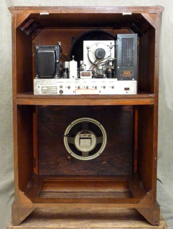
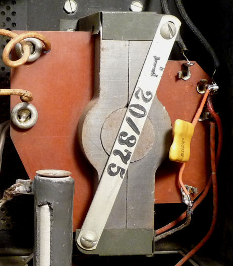
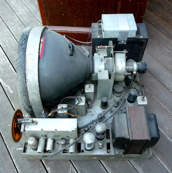
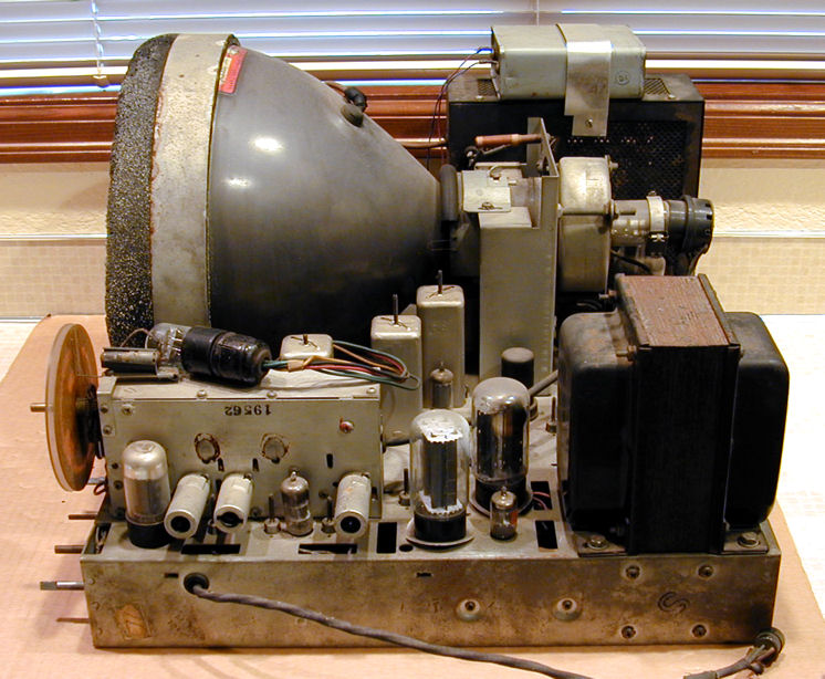
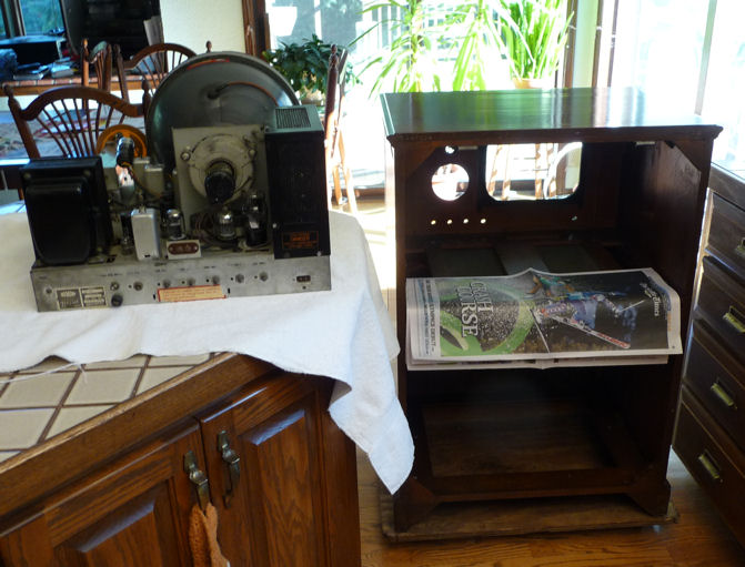
The chassis is complete and looks decent. Strapped atop the
high-voltage cage is a slapdash repair—a large
box capacitor wired to substitute for a filter capacitor
in the power supply. The power transformer is visible at lower right.
It is massive, almost six inches tall, needed to accommodate the two
5U4G rectifier tubes. DuMonts of the 1940s are known for excellent
design and robust construction.

Carrying the chassis indoors (uff da!), I got a first view of its
underside. Nothing scary here. A few capacitors have been replaced
over the decades.
The component layout is roomy, promising a carefree restoration.

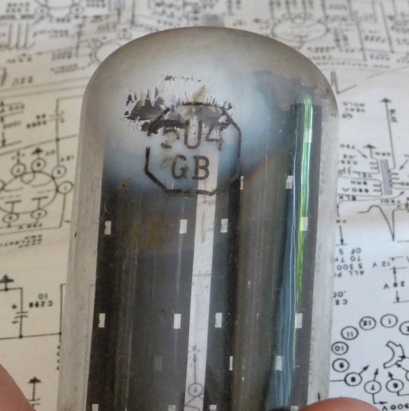
The white material in this 5U4G rectifier suggests that the
tube lost vacuum when it failed. Not to worry, in this deal
I also got a box containing 39 good spare tubes, including two 5U4Gs.
I love goodie boxes! The tubes alone are worth considerably more
than I paid for the whole shebang. I also got four pages
from the service manual, one of which is seen in this background.

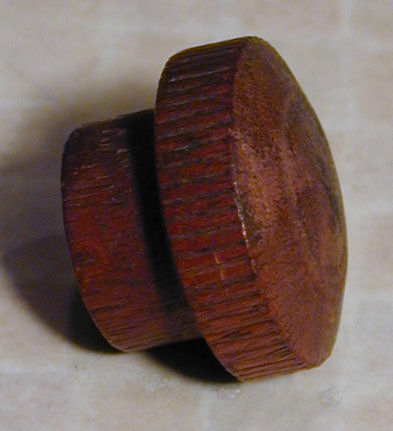
The seller told me that all of the knobs had been lost, but I found this
one at the bottom of the box of tubes.

To complete this project, I'll need four more knobs like this,
plus a large tuner knob.
Cleaning Up
This weary traveler needs a bath and a shave. The usual drill is to wipe off
dust and grime, clean the pins and sockets for every tube (testing each tube
as we go), and use a little DeOxit to clean user controls such
as volume. You can read more about those basics in the article
First Steps In Restoration.
Note the eye tube lying on top of the tuner box.
Remove this by reaching into the cabinet before you slide out the
chassis. Otherwise, you may bust some of those pretty colored cables.

Another minor issue is evident in the previous photo. See how the
base for the picture tube is hanging a bit crooked. It
has come loose from the CRT neck, fairly common when old
glue dries out. I'll resecure the base later with a few drops of
cyanoacrylate (super glue). If I leave the base loose, that risks breaking
the fragile wires leading into the glass neck.
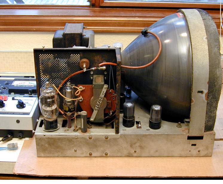
Here I have turned the set and removed the cover from the
high voltage cage. I see a dab of surface rust, but nothing
seriously amiss.

Looking under the little phenolic board that holds the 1B3GT
rectifier tube, I spied a small resistor that looks like it has
gotten very hot. I make a note to replace it.
Here's an odd sight. DuMont put this little permanent magnet in the
back of the high-voltage cage, right behind the 6BG6 horizontal
output tube.

No doubt it is there to suppress Barkhausen oscillations, which appear
as a dark vertical line in the left side of the screen. One of my old
TV service books mentions using a spare ion trap magnet
on a 6BG6 to effect the same cure. (My
Hallicrafters T-67 restoration article
shows a screen with typical Barkhausen's interference.)
The picture tube's high-voltage lead needs help. Where the cap
enters the tube, someone has wound a couple of licks of electrical tape
around the lead. With a gentle jiggle, I can feel loose wires inside.
"Replace CRT lead," I write on my to-do list.
Twenty-two of the TV's twenty-five tubes tested OK.
I replaced the three weaklings from the box of spares that I
got with the television.
The 12JP4 picture tube looked very strong on my Sencore CR70 tester.
On its bell is a sticker from a rebuild shop with the type number.
A properly rebuilt tube can last as long as a factory original, so
this one may have lots of life left.
It looked bright, indeed, when I got a picture later on.

Clean Tuners Are Happy Tuners
The TV's tuner was immovably stuck with prehistoric lubricant,
so I disassembled it for cleaning. I was eager to get a peek inside, anyway.
Removing the tuner demands care. You need to unsolder several leads
under the chassis, as well as the cable leading from the antenna terminal to the tuner box.
Then you remove five screws under the chassis and carefully pull the
leads out.
This and most other service can be done with the chassis standing on its
side, with the high voltage cage resting on the workbench. The service manual tells
you to put the other (power transformer) side down, but that makes no
sense to me. The chassis is perfectly stable this way, and the other
way tends to crush the speaker cable coming out that side of the chassis.
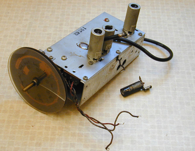
You must also remove the dial lamp by sliding it off its mounting bracket.
The lead to my lamp happened to break off when I moved it, so I left it
in the following photo. The tuner is on the workbench, ready for service.

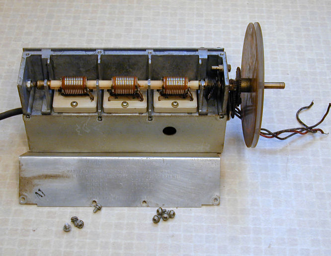
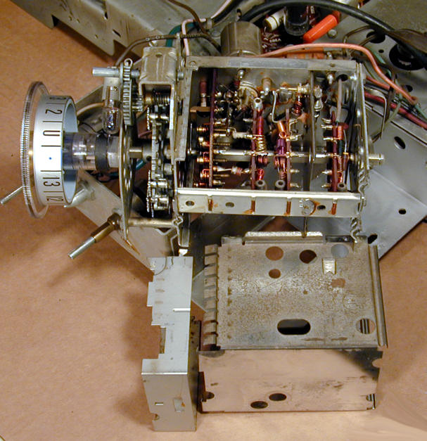
Next, we see the tuner with its hat off. The design is simple and elegant.
Three rotating coils take you through the VHF television and
FM radio frequencies. The workmanship is
admirable. The coils are mounted on a ceramic shaft and the
tuner frame is cast, rather than sheet metal.

Removing the second shield exposes the rest of the tuner. Inside are
trimmers, little coils, and so on. You don't need to remove this
for cleaning and lubrication; I was simply curious. Don't
mess with any of these things or you'll need to realign the
tuner.

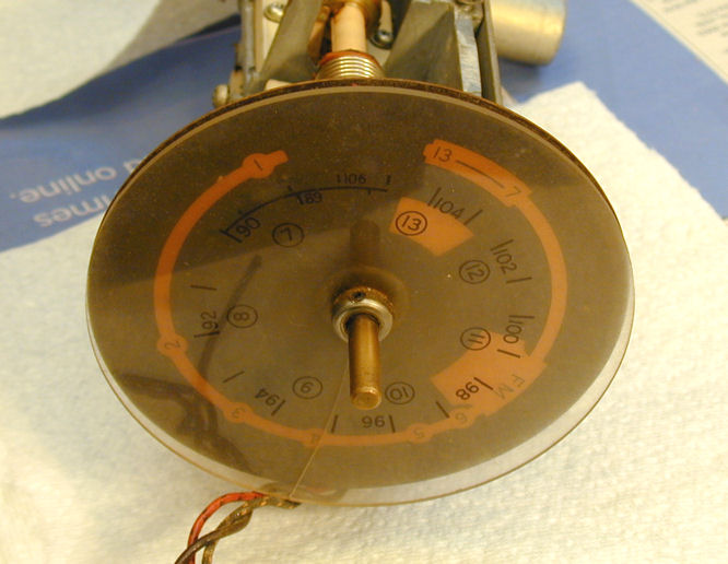
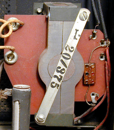
I could see that I'd need to remove the dial, so I took a photo to
record its position, which will be important on reassembly. As
I later found, the tuner had stopped all the way clockwise. Notice
how the two thirteens are aligned. You can also see how the dark
inner dial is visible through the clear outer dial.

The two dials are geared in about a 10:1 ratio. It takes
nine complete turns of the outer dial to make almost one turn
of the inner dial, which stops before completing a full rotation. This
TV has no fine tuner as such, but the outer dial is a fine tuning
aid. Its markings include the FM radio frequencies and TV channels
7-13, occupying the dial's full rotation.
The inner dial shows every
frequency covered by the tuner. Channels 1-6 are spread farther apart,
while the FM frequencies and channels 7-3 are much closer together.
This non-orthogonal spacing reflects the way this tuner works, not
the way that TV channels are allocated in the ether. Every TV channel
is six megahertz wide, whether it's channel One or Thirteen.
My outer dial has a radial crack. I doubt it will bother me that much,
but I made a high-resolution scan of the dial while it was out, in
case I want to make a reproduction some day.
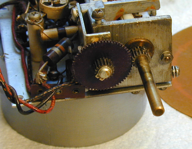
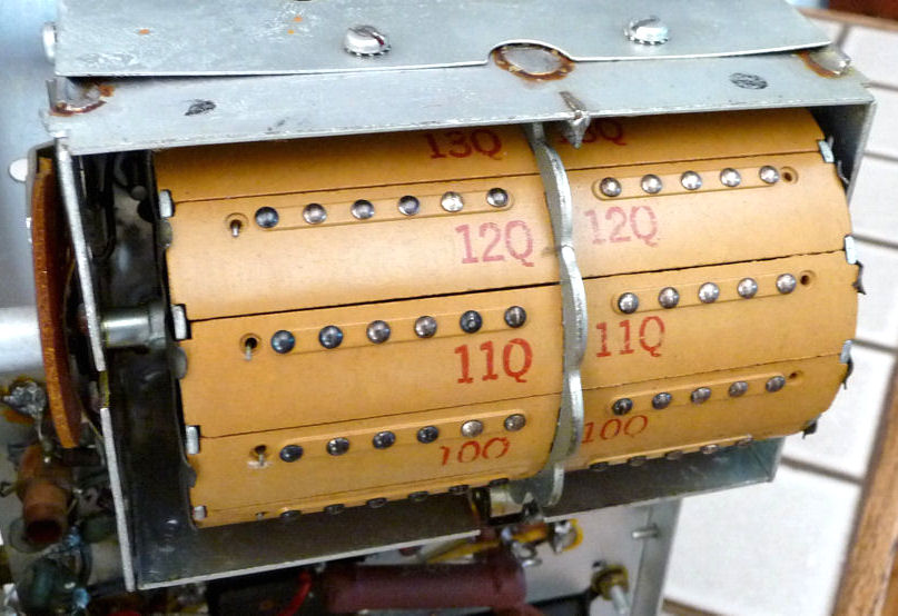
The next photo shows an intriguing gizmo. Look at the
circular plates with little ears, lined up in a stepped or spiral pattern.
I couldn't tell what these did just by staring at them, and since
everything was stuck solid, I couldn't find out by turning the
tuner and watching.
Other DuMont owners told me that these plates create end stops
for the tuner, which has to make nine revolutions to traverse the
VHF band. Each plate can rotate freely, but the ears catch one another,
leaving and interleaving as you go from end to end of the outer dial.
There is one eared plate for every time the outer dial rotates. I
hope they gave a bonus to whoever invented this cunning scheme!
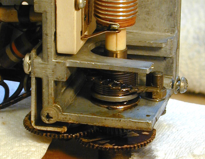
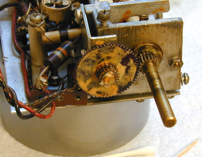
Now I have removed the dials to expose the gear train. The outer
dial is secured on the shaft with little setscrews. When you loosen
it, the inner dial (with its gear) is also freed to slide off the shaft.

The old dried grease looks awful but cleans up easily with Q-tips and
lacquer thinner. I used wooden toothpicks to dislodge bits of it
from crannies.
After cleaning the surface mess, the tuner was still stuck securely.
I dabbed penetrating oil into all of the bearings and let it
marinate overnight. Do not use force to unstick this tuner.
You don't want to damage anything, especially the ceramic coil
shaft, which could be expensive to replace.
Once the mechanism was free, I carefully relubricated everything.
Use only enough lubricant to let things move smoothly. Excess
grease or oil will attract dirt.
Each of the three main coils has a wiper and contact pair on
each end. Clean these, like other electrical contacts, by
dipping a Q-tip in DeOxit and gently rubbing. Follow that
treatment with electronic lubricant, again sparingly applied
with a Q-tip.
The next photo shows the gear train and dials when I'm almost
finished. You can see one of the setscrews on the outer dial's collar.
You don't need to remove the inner gears unless something
has been bent or broken.

Before putting the dials back on, I turned the tuner all the way clockwise,
then aligned the dials as in the earlier photo I had taken.
The tuner is ready to reinstall.
Shining up the outside doesn't make the tuner work any better, but
it was my little reward for working a long time on the hidden
innards. Now it works well and looks good, too.
InducTuner Variants
This tuner lists several U.S. patents on its cover. The patents, such as
2377790,
define underlying technology but don't show this exact mechanism.
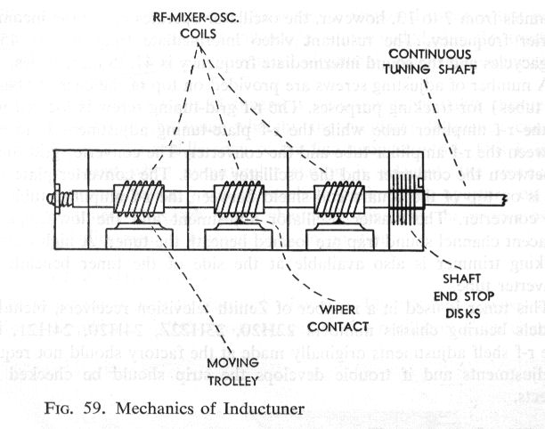
One of my old TV service books describes the InducTuner with this diagram.

Here, the contacts are on the bottom of the tuner frame rather than
the ends of each coil, and the contacts move on "trolleys." I don't know
whether this version was actually produced, but it certainly differs from
mine. If you read 1940s patents for things such as variable inductors, you'll
see many similar gizmos, often quite complex.
DuMont made a later InducTuner with more upright spirals.
Here's a photo from the same book.

Mallory holds U.S. Patent
2666906
on this so-called spiral tuner. Here is one of the drawings.
Click the image below to see a brief video of the
spiral tuner
used in my DuMont RA-113.
Refer to that article for more photos and information.

Continuous Tuner Pros and Cons
The InducTuner was a Mallory product, so any manufacturer could have chosen it.
Other companies didn't rush to embrace the costly continuous tuner,
however, or the integral FM radio that it enabled.
When a TV and radio were desired, it was simpler to bolt an
existing radio chassis into a cabinet and operate it separately.
Most TV/radio/phono consoles were designed in this way. My
Scott 800B "combo" is an example.
An advantage of this setup is that the radio can cover AM
standard broadcast and shortwave frequencies in addition to FM.
FM radio stations are closer together than television stations.
This tuner has a constant rotation, however, so you must move the knob
slowly and carefully in
the FM portion, compared to its TV portion. The clear outer dial helps
you do this, as noted before. I believe that later DuMont
continuous tuners had extra gizmos to give finer tuning
control within the FM radio band.
It's appealing, in a nerdy engineering way, how the InducTuner puts
the actual frequencies in your face. The average person has no idea that
FM radio sits in the middle of the analog TV band.
On the downside, this tuner
is less user-friendly than modern ones that simply click from
one channel to the next. It also lacks a fine tuning control,
which soon became standard.
A different type of continuous TV tuner is found in my Scott 800B and
Pilot TV-37 sets. They
use ganged air variable capacitors like those
found in communications radios.
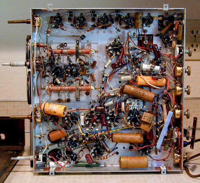
The Pilot's tuner can be seen at the left in this underchassis
view. It is desperately cheap, as befits a budget TV. The tuner
uses pulleys and strings, common in radios but unheard of
in televisions. The tuning dial shaft is second from the top, on the left.

The Pilot does not receive FM radio. A switch toggles
between low TV channels and high ones, bypassing the FM frequencies.
Below is the tuner from the mystery television in
my Scott 800B combo.
The capacitor vanes are continuously variable, but the tuner has
mechanical detents to stop you at the stations. A
separate control is provided for fine tuning.

After years of inquiry, I still have no idea who made this television. It
certainly wasn't Scott, whose sets are well known and do not include this
critter. Scott contracted with other manufacturers to supply TVs in some
of these combos, so I'm guessing that was the case here.
If anyone has a clue about this set, drop me a line.
It has been restored but needs some final touches that I don't want to attempt
without a schematic.
The Scott TV tuner does not enable FM radio reception, either. Internal
switching confines it to television frequencies. Anyhow, who would use
a TV tuner for FM when in the same cabinet you have one of the finest
postwar FM radios that money could buy?
Okay, so a few TVs could receive FM radio "for free," as it were,
but could any radios receive sound from TV channels without extra circuitry?
The answer is Yes, but not many. My Hallicrafters SX-42
boatanchor has continuous FM coverage from 27-110 megahertz. This allows it
to receive TV audio up through channel 6, which ends at 88 megahertz. Channel
7 begins at 174 megahertz, so the SX-42 would be deaf to the higher TV
stations. All of which is academic, now that analog TV broadcasting
has ceased, unless you happen to operate an in-home TV transmitter, as I do.
So, What Kind of Tuners Did the Others Use?
Most television manufacturers used non-continuous tuners of two main
types: the robust (and expensive) turret tuner or the less costly wafer type.
Here is a turret tuner:

Turret tuners are used in several of my vintage TVs, such as the
RCA CT-100, a color set, or the black
and white Admiral 24C15.
Here is the wafer tuner used in my RCA CTC-11 color television.

You can see more of that sort of tuner in my
RCA CTC-11H article.
A Strange Intruder
Back to the RA-103, the next phase is usually the most time-consuming part of any
restoration, replacing capacitors.
I always start with the filter capacitors in the power supply,
so the set can be powered up as soon as it's safe.
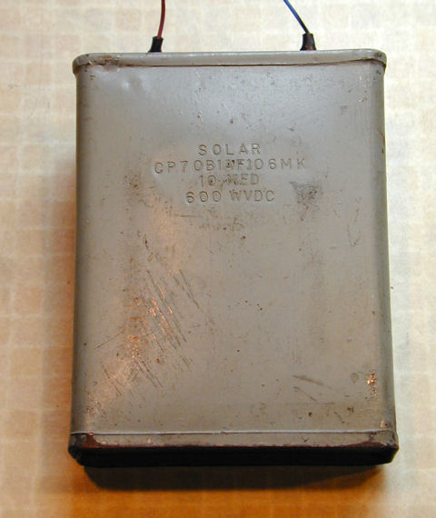
In this case, the filters involved a peculiar box capacitor.
It was mounted on the high voltage cage with "lazy man" wires
leading all the way under the chassis. I suppose it was the only thing that
the tinkerer had on hand, and far too big to fit anywhere underneath.

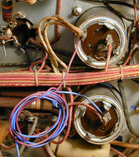
Here's how the strange intruder was connected. In this photo, the red and blue
leads from the box cap have been detached and coiled up. Two can capacitors for
the power supply are visible from their bottoms: C241 (above) and C262
(below). I have also included the power supply schematic.


Look how things are wired. The box capacitor is connected between the positive lead
of C262 and the negative lead of C241. The other leads for those capacitors
are disconnected, removing the original caps from the circuit. Also missing are resistors
R316 and R317, formerly connected in parallel with the original caps to equalize
voltage across them. In place of those four components is the single 10 mfd capacitor.
You wouldn't normally replace large capacitors with one that's
so much smaller. C241 and C262 are connected in series, making 40 mfd.
The replacement is still only 1/4 of the design value. Whether this actually
worked is academic, since I'll put everything back as the
DuMont designers intended.
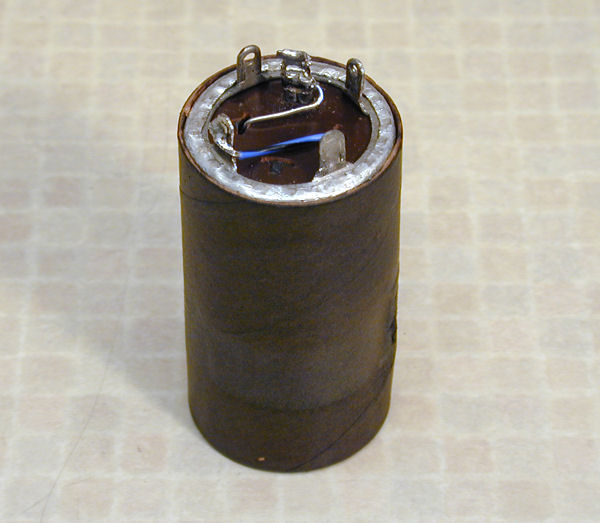
Restuffing a Can Electrolytic Capacitor
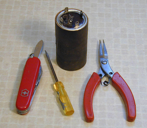
Let's start with capacitor C241. There isn't much room under the
chassis for a new electrolytic, so I'll "restuff" it
by putting a new capacitor in the old can. Here is
the can and the tools we'll use to start.

In this type of can, the negative terminals are on a ring around the outer edge. They are connected
to the metal can. Positive terminals are always located toward the middle.
Although a can may contain up to four capacitors, this has only one, hence
only one positive terminal.
The black cardboard sleeve is an insulator. In some cans like this,
the negative terminals slip through slots in the chassis and are
twisted and soldered. This makes a physical and electrical connection
to "chassis ground." In this power supply, the negative leads
of the capacitors are not connected to chassis ground, so it's
necessary to insulate the can from the chassis. Don't discard this cardboard sleeve
or your TV won't work!
There are different ways to get the insides out of the old can. I often
simply cut the can near the base (see Replacing Capacitors
for more capacitor info). This time, I decided to uncrimp the can and
use the original terminals to preserve a little more authenticity.
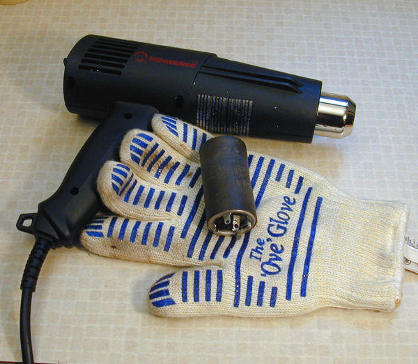
Before we do that, let's soften the adhesive with a heat gun and pull off
the sleeve. The tarry adhesive cleans up easily with
mineral spirits and paper towels.


The next step is to carefully uncrimp the edge of the can so that you
can remove the terminal ring and other goodies from inside. You may have
to use the point of a knife blade to get it started. Work slowly and bend
the edge upward very gradually. The can metal is soft and easily torn.

I usually go around the can about three times before
the edge is fully straightened. I use a small pliers in the later stages.

The metal terminal ring pulls out when the edge is straight.
Below that is a phenolic disc that holds the positive terminal(s).
Underneath that disc is a circle of rubbery insulation and under that
is a second phenolic disc.
With patience, you can carefully pull and pry out these layers. You will
normally break the thin strips of metal that connect the terminal ring and
positive terminal(s) to the capacitor innards. Don't worry about that;
you'll be hooking up wires to your new capacitor(s) later.
The next photo shows the metal terminal ring, two phenolic discs, rubbery
insulator disc, a little strip of metal that formerly made the capacitor's
negative connection to the terminal, and a big wood screw that we'll use to pull
out the capacitor innards.

If you save all three discs, they'll fit snugly into the
can's collar when you reassemble everything.
Fire up your heat gun and pull away! If the innards don't come out easily,
heat the can some more.

In the next photo, I have partially unrolled the layers of foil and
paper that form the capacitor body. The powdery junk is
dried electrolyte. In a new or usable capacitor, this would be a paste.
Some people try to "re-form" crummy old electrolytics by gradually
applying increasing voltage, but this photo shows why such efforts are
usually doomed. I throw this mess into the garbage where it belongs.

The last steps are easy. I connect the new capacitor leads to the terminals:
positive to the center one and negative to an outer one. In this case,
I simply ran the new wires through existing slots in the discs. If
necessary, in a multi-section electrolytic, you can drill tiny
holes for the new wires. You don't need to glue the discs together; they'll
be held in by pressure after you re-crimp the can's edge.
I insulate the lead that runs along the capacitor body and secure it with
three turns of tape. If you like, you can fill the empty space in the can
by winding some plastic or thin cardboard around the new cap.
That can't do any harm, but it's not really necessary. The new cap
weighs almost nothing and shouldn't be bouncing around inside the can
unless you drop the TV off a building.

Slowly fold the edge of the can back down. I use the edge of
a heavy screwdriver. In the next photo, I have just begun the process.

You can do a neat job if you're patient. Don't worry if your first
effort doesn't look perfect. The important thing
is to firmly secure your new assembly inside the can.
The last photo shows the restuffed cap ready to install in the chassis.
A couple of drops of glue inside the sleeve will keep it in place. In
this TV, the can protrudes halfway through the chassis and is secured by
a round metal clamp on the upperside.

Some people put a little label on the capacitor so that future restorers
don't tear it out, mistaking it for a bad original. You can also
attach a note inside the restored set.
High Voltage Capacitors
The RA-103 uses a couple of paper capacitors rated at
1,000 volts. They are C275 and C276, connected to either
side of the horizontal linearity control L219 (see schematic,
Page 2).
This photo shows their replacements, the two pinkish components
near the center.

Needless to say, it's important to use new capacitors of the correct
voltage rating. If either one fails, it may affect more
than linearity.
Maiden Voyage
The first time you power up an old TV is always exciting, yet
nerve wracking. Will it go up in sparks? Will it make a sound?
Will it do anything at all?
After replacing the most critical electrolytic capacitors, I
gave it a try, using a metered variac to increase
power under a watchful eye. I started out with the selector
turned to Radio.
The first gratifying sound was a faint click from the relay,
indicating that the time delay circuit was functional. Moments
later, I heard FM radio and saw the green magic eye light up.
Audio quality was good and the tuning was right on the money.
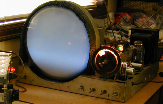
Not bad, but what about the TV? Here's what I saw when
I selected Television.
Not the greatest picture, but the TV is still full of rotten old
capacitors. Under the circumstances, even a blank raster is
a pretty positive sign. I powered down, brewed fresh coffee,
and started recapping.
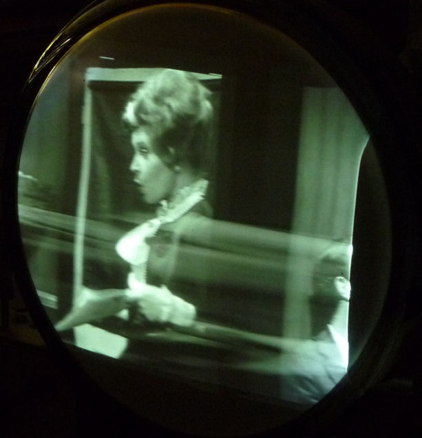
First Picture
That task took me a few hours. Since it was now safe to play the TV, at least for
short periods, I tried it out after every few replacements, watching as
everything slowly came together. First a picture appeared. It grew brighter and clearer.
The already-good audio improved even more. The picture stopped rolling uncontrollably.
Eventually, we got a solid horizontal lock. Voltage checks along the way confirmed
that the TV was gradually regaining overall health.
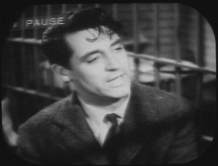
With a stable picture and juicy audio, I can move into finishing mode. I'll get
out my pattern generator to make adjustments such as linearity and centering.
I'll also use an oscilloscope to peek at a couple of waveforms, although
judging by this image, they can't be too far off.
Improving the Focus
Looking back at the previous photo, you can see that the picture isn't very crisp.
Turning the focus control all the way clockwise didn't make it any better.
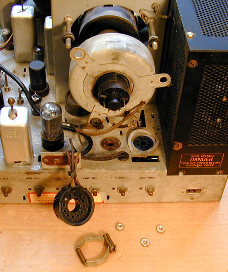
That reminded me of an odd sight I had noticed earlier. See how
the big doughnut around the picture tube neck is slanted?

That's the focus coil, and it normally wouldn't be that far
off-kilter. The photo includes another item of interest—the
ion trap. It is the smaller gray metal collar, located downward in this
photo, between the focus coil and the black tube base.
When I first powered up this set, there was no hint of a picture, only
vague swarming shapes on a very dim screen. It eventually occurred to me
to adjust the ion trap. In the position shown above, it produced a
nice, bright picture.
Having to turn a control all the way to one end often indicates that
something is fishy. The voltage at the focus control was more than adequate,
so possibly the cockeyed focus coil was to blame. In the next photo,
I have loosened the coil on its mount, to replace its wrecked rubber
grommets and try repositioning it. The ion trap has been removed and
can be seen below. It is simply a magnet with a springy collar.
Calling on the friendly folks in the Videokarma
television forum for advice, the consensus seemed to be that, when the
tube was rebuilt, they installed the type of gun that requires an
ion trap, although a 12JP4 tube wouldn't normally have one.
The DuMont service manual stated that the focus coil should be located
1/8 inch behind the deflection yoke, perpendicular to the picture tube neck.
Leaving the ion trap off for the moment, I positioned the coil that way
and tried the TV.
The picture was extremely dim, visible only in a dark room.
The next photos were taken with the focus coil in two positions.
First, the coil is perpendicular. Note the dark upper crescent in the
upper right. The electron beams are missing that part of the CRT.

In the second photo, I have moved the coil off-kilter as it was originally.
The image fills the screen, but it's still unacceptably dim and the focus is
bad.

This confirmed that the ion trap was necessary. I reinstalled it and tried again,
with the focus coil perpendicular as DuMont intended.
With the ion trap in its original position, the picture was completely dark.
Rotating it 180 degrees on the CRT neck brought back a bright picture, but with awful focus.
However, the focus control was still all the way clockwise.
When I turned it back toward the center, I found a nice adjustment point
near the midrange, as you'd expect with a properly functioning control.
Problem solved!
Why did the ion trap and focus coil work right this way?
An ion trap can be adjusted in three ways. I'm guessing that
I inadvertently flipped the trap 180 degrees when reinstalling it,
reversing the polarity. Some traps have a little arrow pointing
to the front of the CRT, although this one doesn't. In any case,
now it produces a bright image. The focus coil is aligned normally and
the focus control works as it should, too.
Life Without AGC
Every early TV is a little different when it comes to picture
adjustments. The RA-103 has no AGC (automatic gain control), as noted
earlier, so you may find yourself adjusting brightness and contrast
more than with other sets.
The lack of AGC is somewhat unusual. My RCA 630TS
has a manual gain control, slightly more convenient than this set. My
T-100, made a few years later,
has AGC, as do all modern receivers.
I had been using this TV for
a while before I noticed this section in the manual.
Normal Operation
With the service selector switch turned to the Television position in
which the pilot light is on, turn the audio volume control to the right
about half of its range, thus turning on the receiver. Turn the Brightness
control almost completely counter-clockwise and turn the Contrast completely
counter-clockwise. Approximately ten seconds after the power is turned
on, a "click" will be heard indicating that the surge
protection relay is energized.
Subsequently, a raster will appear on the picture tube. Adjust the
Brightness control for a moderate brightness, below the point at which
the raster size increases due to excessive drain on the high voltage
power supply. Adjust the focus control for greatest clarity of lines
at the center of the raster.
Turn the Brightness control counterclockwise until the raster just
becomes invisible. Turn the illuminated tuning dial to a television
broadcast station by adjusting the tuning eye indicator until both
green bars are of equal size. Turn the Contrast control to the
right until the proper contrast is obtained.
Once things are approximately set, you won't need to repeat this
entire drill every time you turn on the TV. However, life without AGC means
that the receiver can't compensate for signals of different strength.
When the RA-103 is in radio mode, some FM stations will be much louder than
others. In a modern set, the AGC reduces the signal strength for stronger
stations, so that everything sounds about equal as you move across the dial.
For this radio, you must turn the volume down or up as needed.
The same is true for television reception, and you
may need to tweak picture controls as well as volume.
Early TVs were designed for a world with
mostly-weak broadcast signals and they are sometimes too
sensitive for their own good.
The DVD player that I used to make these screen shots has a
strong signal that can overload the TV, leading to extremes
such as "blooming," in which the image grows much too
bright and loses focus. You may find such differences between a DVD player and a VHS
player, or even between one DVD player and another. Output
devices are not all identical.
The difference is marked when I switch from a DVD
player to my in-home broadcast system, which by its nature
produces a weaker signal. The DuMont actually seems happier with
this over-the-air input. I can obtain a great picture
with less fussing, once the antenna is correctly positioned.
Width Adjustment
Width remained on my to-do list. The picture overscanned the CRT
edges and the width adjuster had no effect. If I
couldn't reduce it before putting the TV back in its cabinet,
the picture mask would cut off a bit more on each side.
Some degree of overscan is common on TVs with round picture
tubes, and the average person wouldn't notice this,
but it annoys me when a control doesn't work at all.
Preliminary checks didn't reveal an obvious cause. The width coil
and flyback transformer checked out OK, as did the voltages on the
6BG6 horizontal output tube and the high voltage to the picture
tube anode.
Referring to Page 2 of
the schematic, T204 is the flyback coil and L220 is
the width adjuster coil. Assuming reasonable voltages on the
relevant tubes, there aren't too many components that could
be at fault. I had previously replaced paper capacitors
C275 (.035) and C276 (.05), both rated for 1,000 volts.
I hadn't checked capacitor C287, in part because it's
a reliable mica and also because it's rated for 1,500 volts and I
don't have that kind of capacitor lying around. A fellow DuMont
owner advised me to check it, however, since it's wired
to the width adjuster.
These photos shows the flyback coil before and after I replaced
C287. The two black insulated leads at upper right go to the
width adjuster. Don't use too much heat when working around coils
like this. The wires coming out of the flyback are delicate!

Replacing that capacitor brought the width adjuster to life. Now I can bring
in the image far enough to see its vertical edges on the CRT.
Not ideal, but better than it was.
Falling Off the Horizontal Wagon
Hoping this project was finished, one evening I brought the chassis into our
family room and sat down to watch a movie on DVD.
Everything looked peachy until about an hour had passed. Then
the TV suddenly lost horizontal sync. Back to the workshop!
This horizontal problem differed from others I had seen before on
this TV. With careful adjustment of the horizontal hold, you could
get a nice upright picture, not a mess of slanted lines. The
picture refused to lock into place, however. Left alone for a moment,
it would slowly slide sideways in one direction or the other,
eventually scrolling faster and faster.
This photo shows another TV with a slightly different problem,
but it gives you a general idea what the picture looked like.

What could this mean? Since we could get a reasonable upright image rather
than a zillion slanty lines, it meant the horizontal oscillator was able
to run at the correct frequency (15,750 cycles per second). But it wandered
higher or lower, unable to lock.
A television gets a 15,750 Hertz signal from two sources. One comes from
the TV's horizontal oscillator tube, which ideally runs at that speed.
The second comes from the horizontal sync pulse embedded in every
television broadcast signal.
Locking these two is the job of a tube called
the "sync discriminator" in this TV. It compares the two
signals, and if the TV's oscillator doesn't match the broadcast's
frequency, the discriminator nudges it back into line, so to speak.
I checked the voltages on the 6AL5 discriminator tube (V214 in
the schematic) and immediately noticed big trouble. Pins 1, 5, and 7
should have very low negative voltages: -1.5, -1.5, and
-1.8, respectively. At those pins I measured positive 287, 287,
and 145 volts. No wonder the discriminator didn't work!
Where could the high voltage be sneaking in? In the
voltage chart, I noticed that pin 8 of V213, the sync clipper
tube, had 300 volts. Between that and the discriminator tube
was a tiny 47pf ceramic capacitor, C247.
Replacing that capacitor solved the problem. Without the bad cap leaking high
voltage into the discriminator tube, its voltages returned to normal.
The horizontal instantly locked and stayed put.
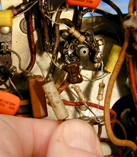
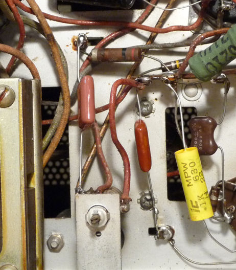
The next photo shows the little tubular culprit, held in front
of the new maroon cap that replaced it. While I was in the neighborhood,
I also replaced three associated 470K resistors.
Ceramic caps, like micas, are pretty reliable, but they do fail
on occasion. High frequencies, as well as high voltages, are hard
on components, and some horizontal circuits have little margin for error.
In this case, one leaky cap was all it took to make the TV completely
unwatchable.
Note, too, that this failure occurred only during an
extended "real world" trial. During restoration,
I had played the TV for many hours in the aggregate, but usually
just long enough to check something. A marginal component may
hang on for a while, yet give up the ghost when exposed to fresh
voltages and the heat of normal operation. Your restoration isn't
truly complete until the set performs reliably for long
periods, as it was designed to do.
We're Halfway Home, Kids!
After many hours of labor, the electronic restoration is complete.
I couldn't resist putting the chassis back in the cabinet
to try it out. Here's the picture at this stage. My
auto-everything camera doesn't make it as sharp as in actual viewing,
but you get the idea.


The DuMont is very enjoyable to watch, and the most stable of all my vintage
TVs.
Cabinet Restoration
The television performed beautifully now, but its
cabinet still looked as rough as the day when I brought it home.
The television was stored in a damp garage for years, and
problems were immediately evident.
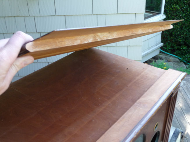
Surveying the Damage
The top had warped badly, eventually pulling itself loose from the top.
The veneer is still attached to the top panel, but I'm not sure whether
the panel can be straightened. Perhaps I'll need to replace it. The
veneer is scratched but salvageable.


The sides have warped and delaminated. The next photo shows how the inner
veneer, as well as the outer, came loose from the solid panel.
At the top of the photo you can see how far the side panel warped
away from the cabinet structure.
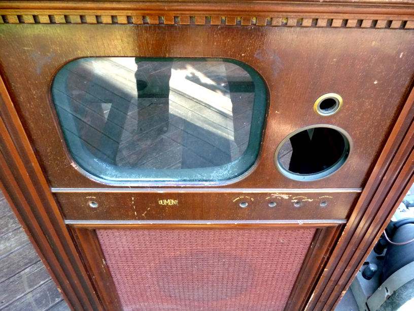
The front finish is cracked and weathered, with a number of nicks and
scuffs. The lacquer is completely scraped off in a few spots near the
knobs, although the decals themselves have mostly been spared.
Reproduction decals for this set are not commercially available.
Fearing that I might have to make my own repros, I took a
series of close-up photos to serve as a starting point for the
decal art.

The grille cloth, fortunately, is undamaged, with no stains
or rips.
The RA-103 has six wooden knobs: five small ones and a big one
for the tuner. I started out with only one, but while
restoring the electronics, I was able to get a set of them from
a fellow collector (thanks, Chuck!). The knobs were almost devoid
of finish, but that's easy to remedy. The second photo shows some
of the knobs and decals, as well as damage in the control area.

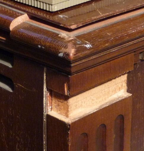
A small piece of molding near the upper left corner fell out years ago
and was lost.
The corresponding piece on the right side was loose enough to pull out when
I examined it. The first photo shows the empty space on the left, where a
replacement will be needed. The second photo shows the
loose molding piece and the space on the right where it came from.
Two new pieces are actually needed: a mirror of the right piece that came out
and a shorter "return" piece to go around the corner of the cabinet.


Time to Call in a Professional
I have refinished a number of wooden cabinets, but I don't have a
woodshop or the skills needed to deal with these structural problems.
I brought the cabinet to a Seattle refinisher, Michael Mueller.
After Michael examined the cabinet, we agreed on a
price and he promised to do what he could for that amount. This
would include fixing the structural problems and improving the finish.
He wouldn't know until later whether the old finish could be successfully
reamalgamated or might require more drastic treatment
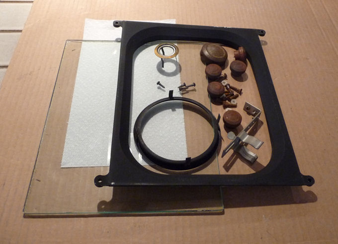
Before delivering the cabinet, I removed the knobs, eye tube bracket,
bezels for the dial and magic eye, safety glass, and the CRT
mask that holds the glass in the cabinet.

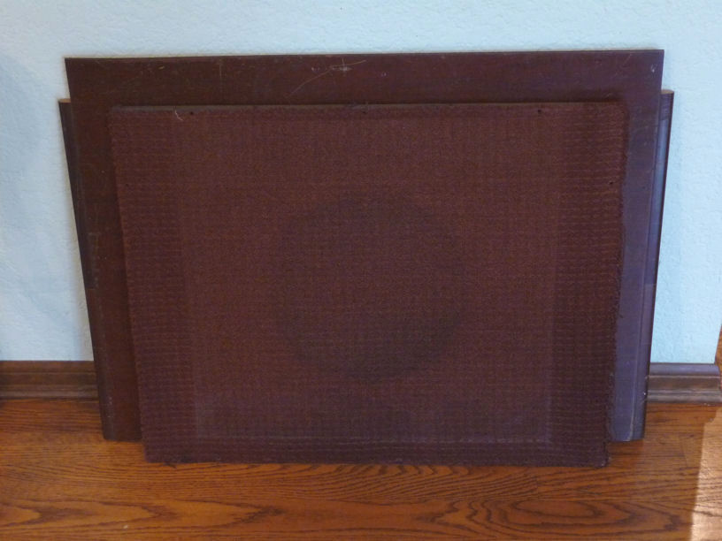
The grille cloth is glued to a board which comes out after removing
ten screws. Here, the board is leaning against the detached
top panel. The cloth is a nice match for the mahogany cabinet color.
It's somewhat faded where it was exposed to light, but
I have seen many old cloths with worse fading.

A couple of days after I delivered the cabinet, Michael sent me some
photos of the work in progress. Here is our friend, the top panel,
undergoing some serious rehab.
That looked a little scary to me, but the straightening was successful,
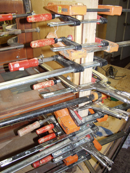
as you'll see later. The next photo shows a side panel in process.
The old veneer was removed from both sides and reglued.
While the glue was curing, Michael began to try reamalgamating the
front panel finish. Reamalgamation softens an old lacquer finish so
that it can be respread. This eliminates surface defects while preserving
the original color and luster. The end result looks like the original
finish because it is the original finish.
I had read about reamalgamation and tried it a few times in the past,
failing spectacularly. In my fumbling hands, the finish ended up one of
two ways: mostly stripped, or a mess of uneven streaks. Michael remarked that
the technique demands practice, as does French polishing.
In the next photo, while the glue on one side is curing, Michael has
started reamalgamating the finish on the top and right side. It's only
partly done, but you can see that the cracking and uneven coloration is
going away.

The project is nearing completion. The absent molding has been fabricated
and installed. The warping and delamination has been repaired.
The top panel is back in place, and the finish is mostly restored. After
more detail work, I'll be able to bring the cabinet home.
Welcome Home, Cabinet
After delivering the cabinet, Michael mentioned that it wouldn't be a bad idea
to apply a coat of finish to the interior. This would help prevent one side
of a panel from drying out (or absorbing moisture) more than the opposite side.
In the next photo, I have applied walnut stain to the interior.
It's time to reinstall the cabinet parts I had removed before refinishing.

The speaker and cabinet hardware are back in place. As soon as my son
shows up to help, we'll slide the chassis into the cabinet.

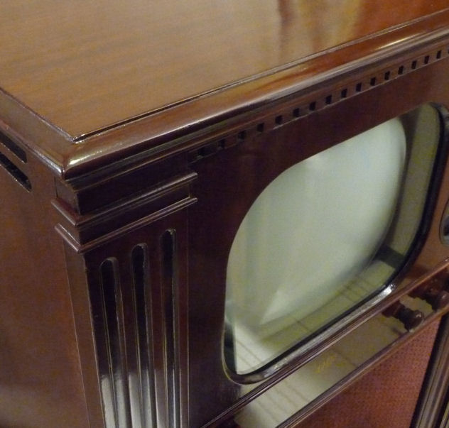
With everything in place, I can take some final photos. Here's a rear
view, much as it looked when the TV left the factory.
Remember that corner with the missing molding? Quite an improvement!
It's hard to believe this is a 62-year old television.
Final Thoughts
This was one of my most satisfying restorations. It's a treat
to work on a set of this caliber. My RA-103 is definitely
a keeper—a TV that I'll use and enjoy for a long time.
How long did this take? I bought this TV on October 5, 2009 and reassembled
it today, February 22, 2010. Four and a half months is not unusual
for me, since I work on these projects sporadically, with frequent time-outs
to putter with other radios and TVs or write articles for this website.
If you're looking for a vintage television project, I'd recommend any
1940s DuMont. They're among the best-designed TVs of the time and
their build quality is second to none. There's nothing particularly
wrong with post-1950 DuMonts, but I think the company lost focus when
Allen DuMont made his ill-starred attempt to create a national broadcasting
network. DuMonts of the 1950s were respectable, but they no longer stood
head and shoulders over the competition as in the 1940s.
|


