Scott 800-B6 Radio/TV/Phono Console (1948)


Built to exacting quality standards, this massive 1940s "entertainment center" was a luxury that
few families of the time could afford. It featured a television, high-fidelity AM/FM/shortwave radio,
and a phonograph with three-speed record changer.
The console employs a whopping 52 tubes, 24 for the radio and 28 for the television.
Weighing in at around 200 pounds, this set was built by Scott Laboratories of Chicago, Illinois,
the successor to the fabled E.H. Scott firm that produced many luxury radios in the prewar period.
The motto of the founder, E.H. Scott, was, "The Fine Things Are Always Made by Hand," and, although
he left the company in 1945, his dedication to quality survived into the postwar era.
I purchased this console in 2002 and had it shipped by truck from Arizona to Washington,
where I undertook a total restoration. Fortunately, the set was in good original condition.
The cabinet and cosmetics were excellent, and the electronics were in basic working shape,
requiring only routine service to ensure safe, reliable operation in the future.
Description
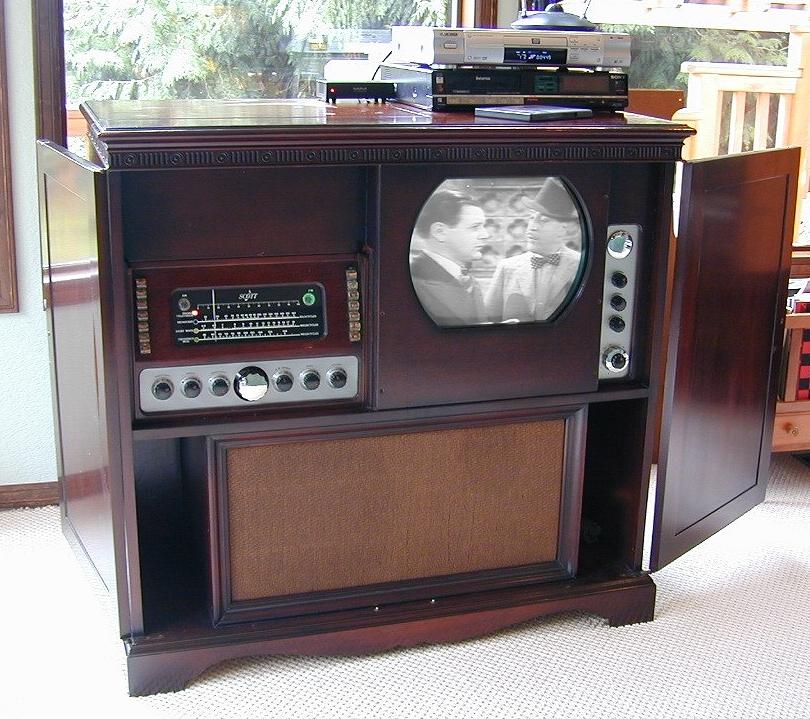
The following photos show the set as restored.
E.H. Scott, a native of New Zealand, made his reputation manufacturing high-performance receivers in the
1920s. In the 1930s, his company helped to pioneer a market for high-end radios, combining top
performance with luxury features such as chrome-plated chassis and custom-built cabinets.
Scott radios were sold separately from their cabinets. Some buyers elected to use the radios "bare,"
enjoying the dazzing display of chrome. Others could choose from a variety of factory cabinets or
hire a local cabinetmaker to house the treasured receiver in a custom case.
Scott's "Made by Hand" credo ensured customer satisfaction—for those who could afford
it—but it also made for a dizzying array of combinations which are hard to catalog
completely. This console is no exception. Whereas the radio and turntable are easy to identify,
I have not been able to find the manufacturer of the television. (More on that later.)
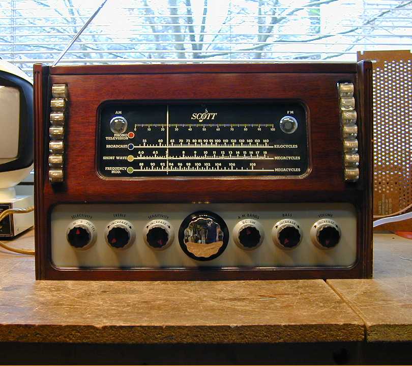
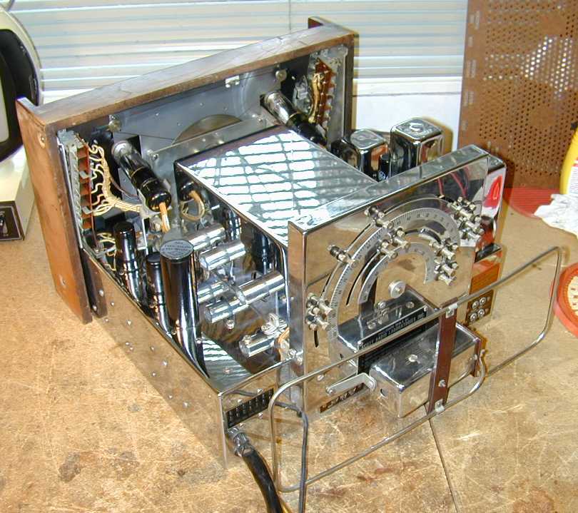
The 800-B6 radio in this console is a real beauty, featuring chrome-plated chassis and a faceplate
designed by Walter Dorwin Teague. The same designer was responsible for two of the most dazzling
radios of all time, the blue-mirrored Sparton Bluebird and Nocturne.
Unlike the flashy mirrored sets, which had average electronics, this was one of the best-performing radios
of its time, with coverage of FM, BC (standard broadcast), and shortwave bands, a high-fidelity
audio section featuring a 15-inch coaxial speaker, a motorized automatic tuner, and various
other high-end features.
This is my second 800-B6, so rather than repeat a lot of information about the radio,
I'll refer you to my first 800-B page for a more detailed description of the
receiver and general restoration notes.
The television uses a 16-inch direct-view CRT and receives channels 2 - 13.
It is divided into three chassis: one holds the tuner, IF, and audio stages;
a second holds the CRT, video output, and low-voltage power supply; the third chassis contains the vertical and horizontal
sweep circuits and the high-voltage power supply.
The TV uses a small 5-inch speaker of its own but it also includes an
audio output for the radio. If you power up the radio and switch it to TEL mode,
the TV's sound is heard in hi-fi through the radio's 15-inch coaxial speaker.
The Webster-Chicago record changer appears to be good quality, although I'm by no means an
expert in phono equipment. It required no service apart from routine cleaning and lubrication.
First Look
The next two photos show the unrestored console sitting in my garage on the day of delivery. Except
for the record changer, which was shipped in a separate box, all the other chassis were left in
the cabinet. Fortunately, nothing broke loose or was damaged during the long journey.
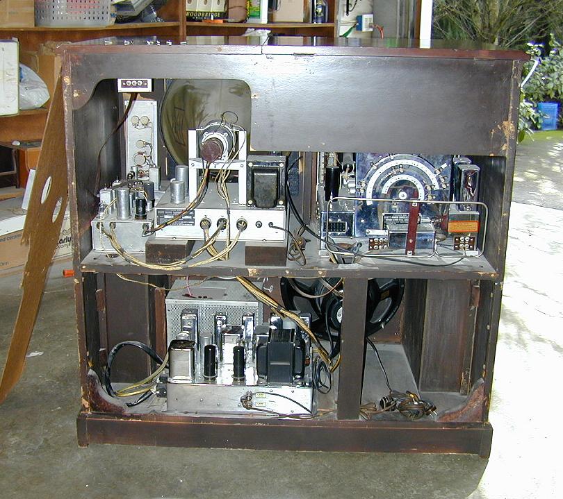
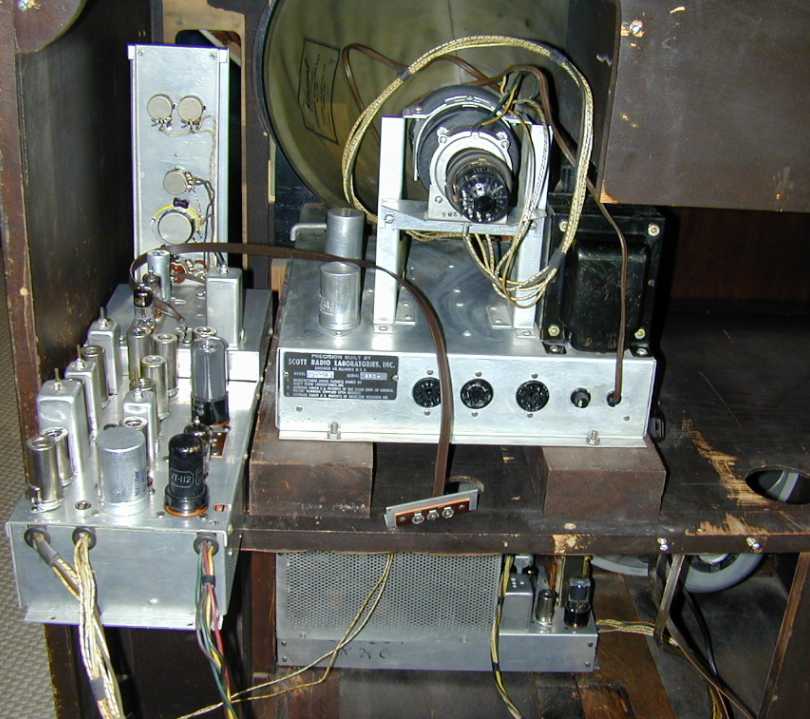
The rear view shows the basic chassis layout. At upper right is the radio tuner chassis. Two of the
TV chassis (tuner and CRT) are at upper left. At lower left are the radio power/audio chassis (nearest
the cabinet back) and the TV power chassis. The 15-inch coaxial hi-speaker can be seen at lower right.
The TV's 5-inch speaker is not visible in this view.
Cabinet Restoration
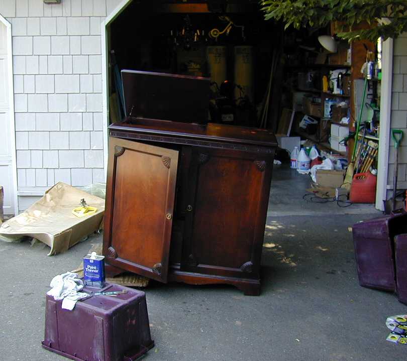
With such a large project, it's hard to know where to start! After removing all the chassis—a project
in itself—I decided to begin with the cabinet. The next photo shows the cabinet out in my driveway,
after getting an initial cleanup with soft cloths, a toothbrush, and paint thinner (mineral spirits).
Since the cabinet had only a few minor nicks and scratches, little work was needed.
To blend the scratches in with the old finish, I lightly wiped down the entire cabinet with
thin mahogany stain, let it soak in for a while, then buffed it off with a clean,
soft cloth. This masked the little blemishes without altering the character of the original finish.
The interior wooden parts, including the radio's front piece, were in such good condition that
they required nothing but cleaning. If only the rest of the project were so simple!
Restoring the Radio
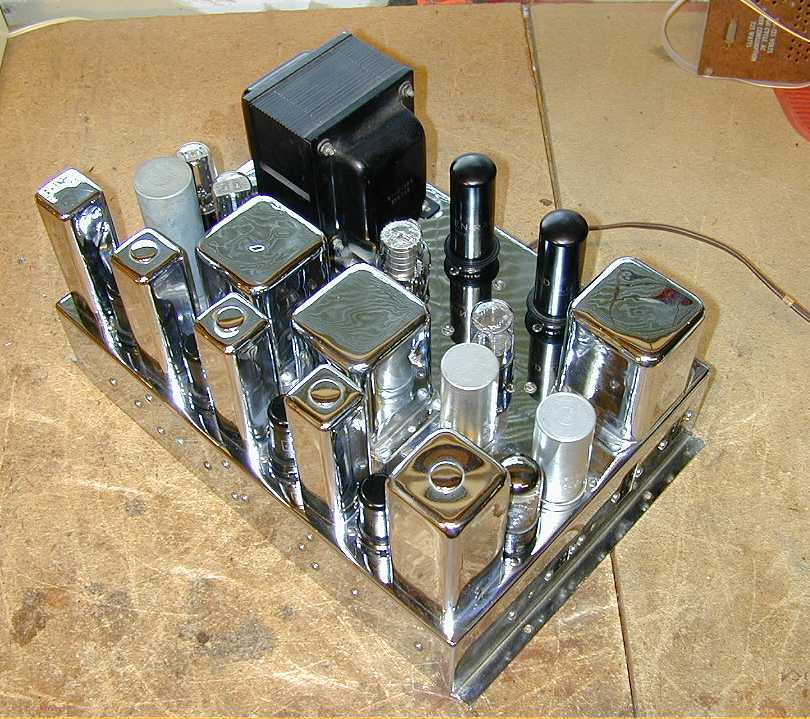
Because I was already familiar with the 800-B6 radio, I decided to tackle that first. The next three
photos show the unrestored receiver chassis. On this chassis, as well as the power/audio chassis,
the chrome is absolutely perfect. My other 800-B6, on the other hand, has some flaking of the
chrome, which is more typical of sets that have not been kept in an absolutely dry environment.


I learned something new when working on this 800-B6. When restoring my first one, I left in place all
of the large, metal-cased "bathtub" style capacitors, on the assumption that they were high-quality
oil-filled caps, which rarely degrade. A fellow collector informed me, however, that some of the
"bathtubs" were actually metal-cased paper capacitors, every bit as unreliable as the paper type.
What's more, there's no simple way to tell oil-filled bathtubs from paper ones, so you just need
to test them all.
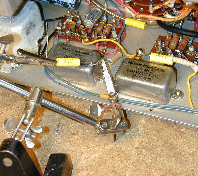
When I tested the bathtubs in this receiver, I found that they were leaky, as one would expect of any
paper capacitor of this vintage. So, out they went! The next two photos show how I wired in some new
replacements, leaving the old bathtub cases in place and using one terminal of each old capacitor
as a mounting point for the new one. In this way, if some future owner decides to hide new
capacitors inside the old cases for a more original under-chassis appearance, the old parts are
right there for the taking.


The rest of the receiver chassis required only the usual attention, carefully cleaning all of the
tube pins and sockets, as well as controls, with DeOxit cleaning spray. I also cleaned the relay
contacts and carefully lubricated key points in the motorized tuner.
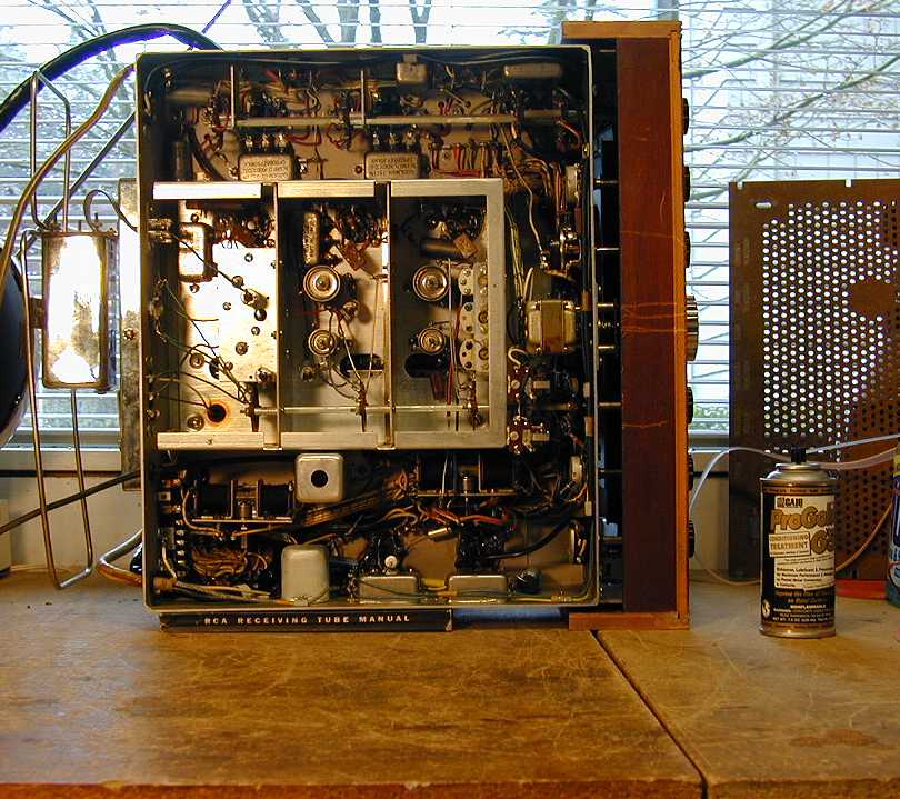
The next photo shows the radio's power/audio chassis.

Restoring this chassis was straightforward, except for
one little surprise. After the recapping was finished, I removed the tubes to clean their pins
and sockets, then connected both chassis to one another and to the speaker, to try out my
newly refurbished radio.
To my disgust, the radio not only didn't play, but emitted a soft Bang! with a puff of brown
smoke from under the power/audio chassis. Quickly powering down, I inspected the chassis and
found that a small electrolytic capacitor wired to one of the output tubes had exploded.
This event was the occasion for a thorough double-check of all the work I had done on
that chassis, comparing the values of all components and their wiring to the schematic.
Finding no discrepancies, I then looked carefully for any mistakes such as a short-circuit
caused by a dropped blob of solder.
Wondering whether the output tube had been blown, I pulled it out and noticed that
it had a broken key on its base. The key on the bottom of an 8-pin tube fits into a
matching slot in the socket, ensuring that you can't plug the tube in the wrong way. When
the key is broken off, however, you can plug it in any which way. It had been my bad
luck, after cleaning the tube and reinserting it, to insert it in a way that sent high
voltage where it didn't belong, instantly blowing the little capacitor.
Grumbling, I replaced the blown capacitor and inserted the tube correctly.
The radio received well on all bands.
Although the radio seemed functionally solid, I noticed a small amount of "amplifier hum" in
the audio. This is not the loud buzzing which results from bad filter capacitors, but something
more like the "PA hum" that you may remember from listening to bad sound systems in
your high school assembly. After checking some obvious things, I sent a query to the
rec.antiques.radio+phono newsgroup, which eventually resulted in a solution.
Since that was a long discussion, I'll provide a link to the
Google archive rather than repeat it all here.
To make a long story short, it appeared that the hum was due to excessive gain in the output section, which I
reduced with a small modification.
Two chassis down, and only three more to go!
Restoring the Television
This 30-tube television is divided into three chassis. Here is the tube lineup:
| Type |
Chassis |
| 16AP4 |
Video/LV |
| 6C4 |
Video/LV |
| 6AU6 |
Video/LV |
| 5U4G |
Video/LV |
| 25Z66 |
Video/LV |
| 6K6GT |
Sweep/HV |
| 6AL5 |
Sweep/HV |
| 12AU7 |
Sweep/HV |
| 6AC7 |
Sweep/HV |
| 6BG6 |
Sweep/HV |
| 6K6 |
Sweep/HV |
| 5V4 |
Sweep/HV |
| 1B3GT |
Sweep/HV |
| 1B3GT |
Sweep/HV |
| 6J6 |
Tuner/IF |
| 6J6 |
Tuner/IF |
| 6J6 |
Tuner/IF |
| 6AU6 |
Tuner/IF |
| 6AU6 |
Tuner/IF |
| 6AL5 |
Tuner/IF |
| 6AT6 |
Tuner/IF |
| 6AU6 |
Tuner/IF |
| 6AU6 |
Tuner/IF |
| 6AU6 |
Tuner/IF |
| 6AU6 |
Tuner/IF |
| 6AU6 |
Tuner/IF |
| 6AL5 |
Tuner/IF |
| 25L6 |
Tuner/IF |
| 12AT7 |
Tuner/IF |
| 6AC7 |
Tuner/IF |
The video/LV-power chassis and tuner/IF chassis sit side-by-side on
the cabinet's upper shelf, while the sweep/HV chassis sits below. The next photo shows how they are arranged.
Here, the narrow tuner has been slid back a few inches, preparatory to removal, while the Video/LV power
chassis is still bolted to its 2x4 supports.

The video/LV chassis is rather sparse. The picture tube wears a heavy plastic overcoat for insulation.

The back of this chassis bears a metal label identifying this as a Scott Labs
model 9T40. My research, including talking to some Scott experts, has not turned up any
reference to (or schematic for) any Scott radio or TV with this model number. As a result,
I had to restore the TV without a schematic. Presumably, Scott contracted with some other
manufacturer to supply this television. If anyone knows which company
made the TV, please contact me.
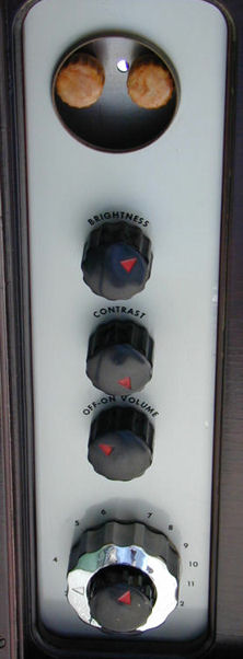
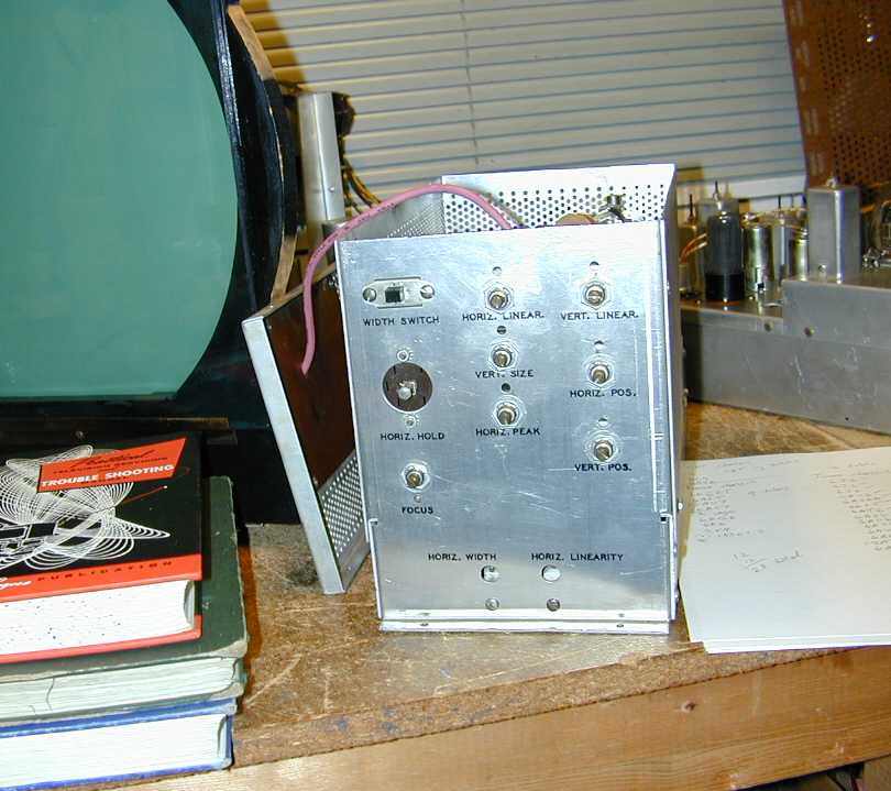
With its distinctive vertical set of knobs to the right of the CRT, the TV should be easy to recognize
from a picture. The TV's vertical and horizontal controls are hidden under a round chrome cover at the top of
the control panel. (The cover was removed for this photo.)
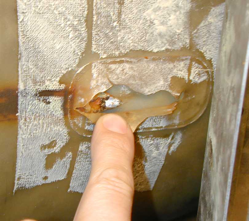
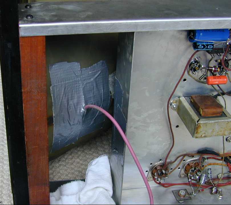
The three chassis are interconnected with various cables, most of which need no explanation. Take care
in removing the high-voltage cable between the power supply and CRT, however. The next photo shows
what can happen if you're careless.

As originally designed, the high-voltage CRT cable plugs into a socket in the high-voltage cage. You should be able
to remove the top cover of the high-voltage cage, unplug the cable, thread it up through
the hole in the cabinet shelf, and leave the HV cable attached to the CRT.
On my set, some past repairman had yanked on both chassis until the cable gave way, breaking the socket
out of the HV chassis. To get the TV out of the cabinet, I unsoldered the cable at this connection point
on the bottom of the CRT, which had been plastered over with duct tape.
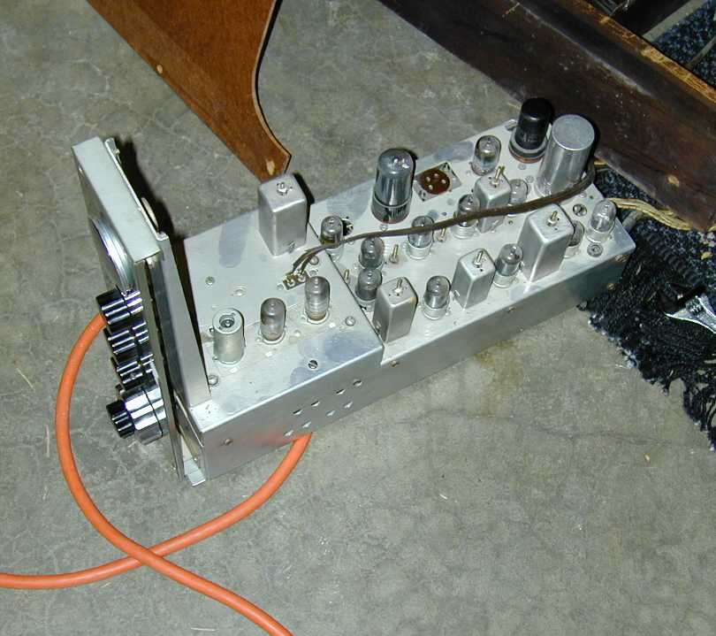
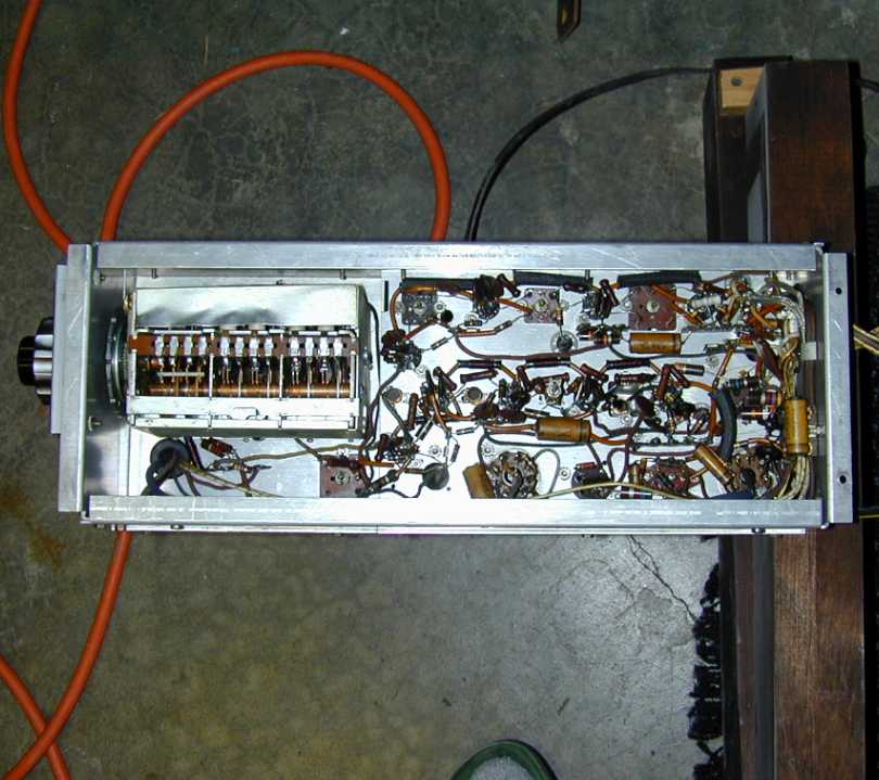
The tuner/IF chassis is shown in the next two photos, sitting on the workshop floor on the day the set was delivered.


As seen in the under-chassis photo, this tuner is not the "turret" style which became almost universal
in later tube televisions. Instead, it uses a set of ganged, continuously-variable air capacitors, more
like something you'd expect to see in a communications radio. The main tuning
knob clicks through a series of detents for coarse tuning to each channel, while the fine tuning
knob operates a trimmer.
You can read about other continuous tuners in my DuMont RA-103
article.
Restoring the TV did not involve any special mysteries. It basically amounted to
replacing capacitors and then tweaking the picture controls as needed
for best picture.
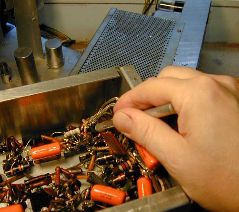
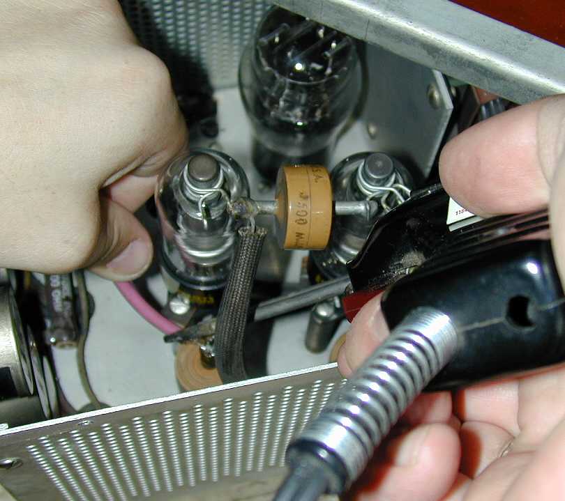
One little capacitor in the tuner chassis was almost hopelessly buried under other components.
Rather than remove all those components to reach it, I used a thin razor saw to cut the
leads, as shown in the next photo. With the old capacitor out of the way, I was able to
install the new one using my thinnest soldering iron.

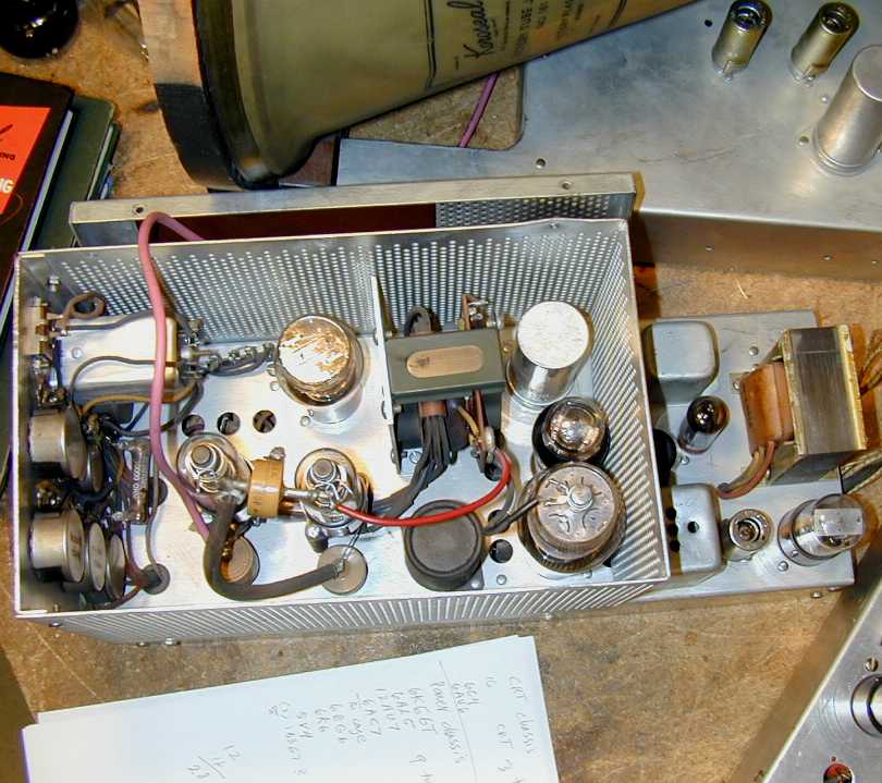
The sweep/HV chassis has a lot of components inside its high-voltage cage, including two 1B3GT
tubes in a voltage-doubler arrangement. In the next photo, they are seen connected by
a ceramic "doorknob" style capacitor.

This chassis also contains the vertical and horizontal sweep circuits. When everything
is installed in the cabinet, the sweep controls are accessible through an opening in the record storage space
to the right of the speaker grille.

At last, the TV was ready. It played nicely and the operating voltages looked healthy. Lacking
any better solution, I reinstalled the CRT as the previous repairman had done, soldering the cable
to the tab on the CRT, covering it with duct tape, and soldering the other end into the power chassis.


Here's the TV in action, playing an old Hitchcock movie (The Lady Vanishes) from a DVD:
Now that the radio and TV are finished, I can appreciate the value of piping the TV's audio
through the radio's output stage. The sound is vastly superior. This must be the only vintage TV
that can play through a 15-inch coaxial speaker with push-pull audio!
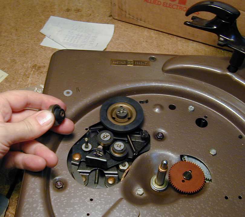
Restoring the Record Player
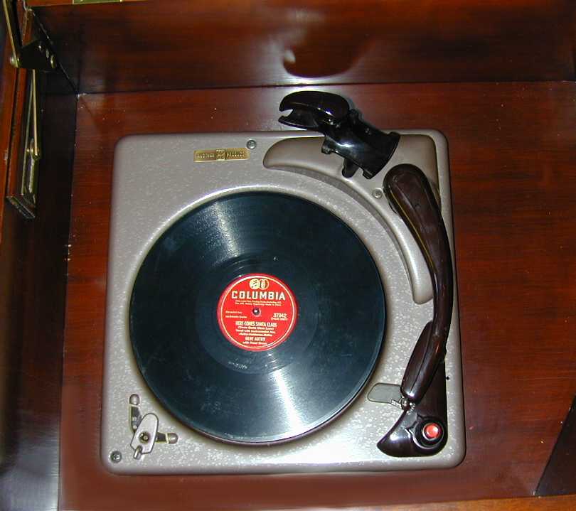
This console is equipped with a three-speed Webster-Chicago Model 356-27 record turntable and changer. A hinged lid on the top of
the cabinet opens the changer compartment, which lies above the radio. As with the television receiver, I suspect that
Scott used a variety of record changers in 800-B6 consoles. If anyone knows of other models being used, I'd like to hear
about them.
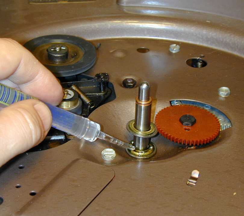
This phono changer was in great condition, needing only some cleaning and lubrication.
Be sparing with lubricants, Excess goo can attract dirt and foul other parts of the
mechanism.


Here is the refurbished changer installed in the cabinet a few days before Christmas, 2003, all ready to play
the 78 platter, "Here Comes Santa Claus," by Gene Autry.

When you install the record player, be sure to plug its power cord into the "Phono" power jack
in the radio's power/audio chassis. Then the changer will automatically come on when you switch
the radio to Phono mode.
Final Thoughts
Is this the console for Everyman? Certainly not. The size alone makes it impractical for many households, and its
complexity makes for a challenging restoration project. If you want the very finest in late-1940s audio and video,
however, there are few sets that can rival its performance. Since completing the restoration, I have
enjoyed many hours with this set, including watching the Super Bowl with hi-fi sound.
|