Scott Model 800-B AM/FM/SW Radio (1947)


The Scott Radio Laboratories Model 800-B is a better-quality
postwar tube radio. With a dual chrome-plated chassis, 24 tubes, and a host of
features, this set was aimed at well-heeled buyers.
The 800-B receives FM and shortwave in addition to the standard broadcast (AM) band.
Motorized pushbutton tuning and high-quality audio make this set convenient, as well
as enjoyable to use. Special-order 800Bs equipped with a remote control allowed the listener
turn the radio on and off, adjust the volume,
and tune in preset stations with the remote.
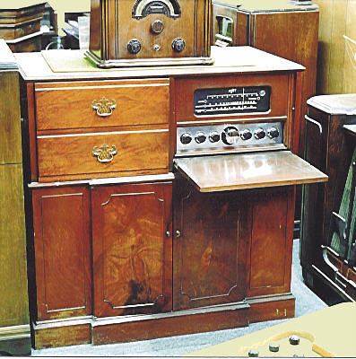
The first photo gives you a general idea what the Scott 800-B looks like in a cabinet.
(The photo actually shows an earlier model that lacked shortwave
coverage and had no motorized tuner.)
Several factory cabinets were available, featuring
mahogany or walnut veneer and brass hardware.
The console shown above is not my radio. It belongs to an acquaintance whose
collection I photographed several years ago (see A Visit to Radio Heaven).
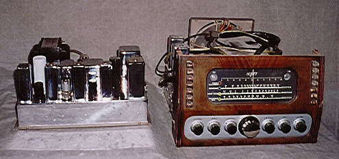
The radio which I own is a bare chassis, without cabinet or phonograph. The next photo
shows my 800-B, complete with vintage dust, immediately after I bought it.
The larger chassis, shown on the right, contains the tuner, all
AM receiver circuitry, and the FM RF section. The smaller chassis on the left
contains all power supply components, the audio amplifier, and the rest
of the FM circuitry.
The 800-B is effectively two separate receivers—AM and FM—with
a common power supply, audio amplifier, and controls. The radio has
separate magic tuning eyes for AM and FM, one on each side of the dial.
The radio's front panel was designed by Walter Dorwin Teague, a famous designer
of the time who also created the stunning Sparton Bluebird and Nocturne
mirrored radios.
The large, fluted, chromium knob below the dial is the main tuner. Scott ads
of the day described it as a "handsome hunk of chromium!" The other
knobs are dark plastic with dark red triangle indicators. All of the knobs
are mounted on a faceplate of greyish brushed aluminum.
Two rows of
pushbuttons are found on either side of the dial. In addition to switching
power off and on, the buttons allow you to switch between AM and FM and
to choose preset stations.
Early 800-Bs have nine preset buttons for AM and three buttons for FM.
Later sets allow you to program any button for either AM or FM. My radio
is clearly a native of Washington state. Its preset buttons still carry labels
for local stations such as KIRO 710 AM.
The 800-B uses 24 tubes, including two magic tuning eyes. Here
is the tube lineup:
| Tube |
Type |
Function |
| V1 |
6SK7 |
AM RF amplifier |
| V2 |
6J5 |
AM oscillator |
| V3 |
6SA7 |
AM mixer |
| V4 |
6SK7 |
AM IF amplifier |
| V5 |
6SK7 |
AM IF amplifier |
| V6 |
6H6 |
AM 2nd detector |
| V7 |
6E5 |
AM tuning eye |
| V8 |
6AG5 |
FM RF amplifier |
| V9 |
6C4 |
FM oscillator |
| V10 |
6AG5 |
FM mixer |
| V11 |
6AC7 |
FM IF amplifier |
| V12 |
6AC7 |
FM IF amplifier |
| V13 |
6SJ7 |
FM limiter |
| V14 |
6SJ7 |
FM limiter |
| V15 |
6H6 |
FM discriminator |
| V16 |
6E5 |
FM tuning eye |
| V17 |
6J5 |
1st AF amplifier |
| V17 |
6J5 |
1st AF amplifier |
| V18 |
6J5 |
2nd AF amplifier |
| V19 |
6SL7 |
Phase inverter |
| V20 |
6L6 |
Audio output |
| V21 |
6L6 |
Audio output |
| V22 |
5Y3 |
Rectifier |
| V23 |
5Y3 |
Rectifier |
| V24 |
0D3/VR150 |
Voltage regulator |
With two stages of AF amplication and a push-pull final audio stage, the 800-B
has plenty of oomph. Separate bass and treble tone controls let you adjust the
tone to your liking.
The 800-B has three additional controls more commonly found on high-performance communications receivers.
The three-level selectivity (bandwidth) switch lets you choose broad, medium, or narrow selectivity.
This is useful for shortwave listening when stations are crowded close together. Narrowing the
selectivity lets you zero in on the desired station and exclude interfering signals from its neighbors.
Under uncrowded conditions, you can choose broader selectivity for better audio.
The continuously variable sensitivity control lets you lower the receiver's sensitivity
to avoid being overpowered by very strong signals.
If you click past the stop at the top
of the sensitivity range, you switch on the radio's noise filter circuit. The filter is
useful for removing "spiky" type noise, such as interference from the ignition of a
poorly shielded auto engine. You can use the filter at any time, although, again, it
is most useful for shortwave listening.
The sensitivity and selectivity controls operate only in AM mode, where they are useful
for "DX-ing" weak and distant stations. AVC (automatic volume control) is available in AM mode,
but not in FM. As a result, you may find yourself turning the volume down for very strong
FM stations.
The power supply is conventional, but it includes an extra voltage regulator
tube to maintain stability if your line voltage fluctuates. This is another feature
found on expensive communications
receivers such as my Hallicrafters SX-88.
The power supply includes two transformers, one to power the receiver
circuitry and the other to power the drive motors and relays.
The 800-B has three relays, which are used to switch the power on and
off, switch between FM and AM modes, and mute the audio when changing stations
via the motorized tuner. Two motors are used, one for the automatic tuner and
one to change the volume via the remote control.
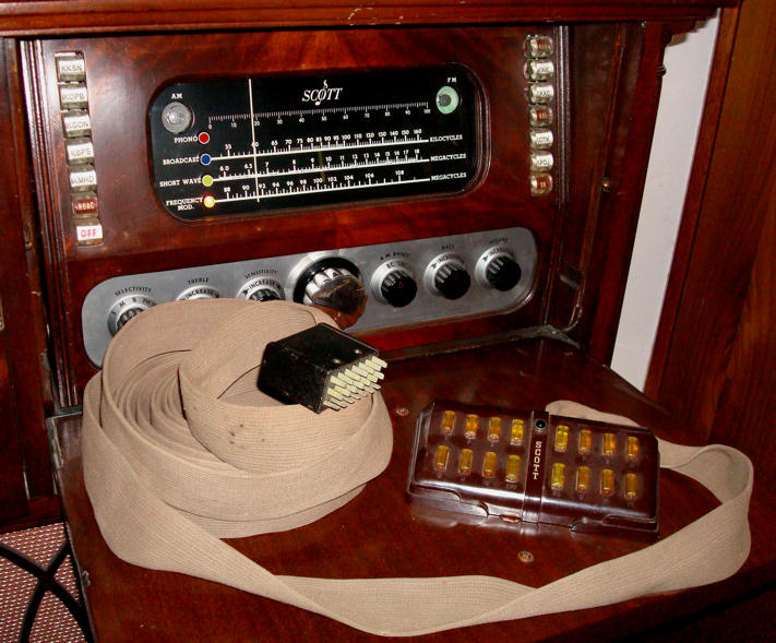
Much of this radio's mechanical
complexity derives from the remote control. Duplicating controls on the remote
dictated the use of relays and motors rather than simple manual switches and controls.
I have never seen a remote in person. A few years after I first published this
article, a visitor emailed me a couple of photos, noting that someone had paid
$650 for this scarce item.

The 800-B is an electromechanical marvel, but the many moving parts and
mechanical contacts can make it a repairman's nightmare.
If you service an
800-B, pay close attention to cleaning and lubricating all contacts, motors,
and relays. I recommend doing this before attempting to power
up the radio, in fact. If a relay or motor is frozen in the wrong position,
applying power could cause expensive damage. The motors are practically impossible
to replace unless you cannibalize another 800-B.
Initial Cleanup
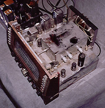
My 800-B was extremely dirty at the time of purchase. The next photo shows the tuner
chassis from above. As you can see, I had just begun wiping the dirt from the
beautifully chromed chassis.
The following photo gives a closer view of the cleanup process. Look at all the
dirt on that paper towel!
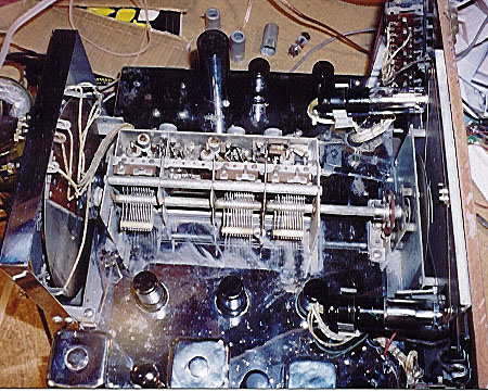
In the next photo, most of the surface dirt has been cleaned up. A large chrome
cover has been removed, exposing the radio's large tuning capacitors. In this
view, the radio's knobs and tuning dial are to the right. The large circular
apparatus at the left of the photo is the auto-tuning backplate. We'll look at
that interesting gizmo in more detail later in this article.
Chromium-plating was a luxury feature on Scotts and similar high-end
radios. Unfortunately, the chrome used on Scott chassis was not the
best quality, tending to rust and peel over the years. The chassis on
my 800-B is pretty decent, but it does show some light rust pitting
here and there. The tops of a few of the transformer cans show some
peeling, too.
It's possible to have chassis parts re-chromed, but that would involve
stripping the chassis and then completely rebuilding it—a gargantuan task for a set of this
complexity. Since the chrome on mine is not that bad, I'll just live with the blemishes
for now. If I eventually build a cabinet for it, nobody will see the chrome, anyway.
The mahogany wood on the front panel is in excellent shape, needing no restoration.
Electronic Restoration
When I bought this radio, it was missing the original speaker. It also had serious power-supply
problems, as I later discovered.
Substituting Speakers
Before powering up the radio, I had to lash together a replacement for the missing speaker.
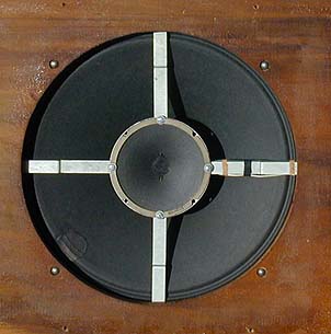
The original 800-B speaker is a 15-inch coaxial unit, meaning that it has two
speakers mounted on the same frame. One speaker is the bass and the other is a tweeter.
The speaker assembly includes a crossover network to route high frequencies to the
tweeter and lower ones to the bass driver.
The speakers are electrodynamic and their
field coils serve double duty as chokes in the power supply filter circuit.
In plain English, this meant that I couldn't power up the radio at all until I duplicated the missing circuitry.
Since I didn't have two electrodynamic speakers lying around the workshop, I used two permanent-magnet speakers instead. To subsitute for the field coils,
I wired in two resistors which gave the same resistance value as the original chokes.
These, along with the crossover components, were soldered to the multi-pin Jones type
plug that connects the speaker to the audio/power chassis. Fortunately, whoever
removed the chassis from the cabinet had the sense to unsolder that plug and
stick it in the chassis rather than leaving it behind on the speaker cable.
The resulting setup was not pretty, but it did work. With speakers wired up and
the rest of the circuitry in place, I was ready to power up the radio for the
first time. Before doing so, I had cleaned and lubricated all the radio's contacts
and controls, replaced bad dial lamps, tested all of the tubes, and replaced a few weak ones.
Firing It Up (Literally!)
As found, this radio had a short circuit in the first filter capacitor
of the main power supply. After replacing that capacitor, I slowly brought up the power
using an autotransformer. The radio played on all bands, but after a few moments
I heard a sizzling sound from one of the two rectifier sockets.
Looking more closely, it appeared that the socket was starting to bubble and melt!
I quickly powered down and did some testing. Perhaps the socket was carbonized
inside, providing paths for high voltage to leak to the chassis. This damage might
have occurred when the radio continued running after the filter capacitor failed.
In any case, both rectifier sockets had a strange, mottled appearance. I decided
to replace both of them.
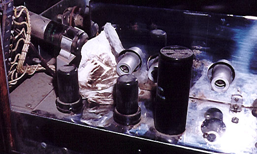
Replacing Rectifier Sockets
The following photo shows the rectifier sockets. One of them, at the bottom, has already been unwired.
In the upper left of the photo, you can see the base of the defective filter
capacitor. It has a large hexagonal mounting screw and has also been disconnected.
Looking more closely at the defective filter capacitor, I saw that it must
have suffered catastrophic failure. The aluminum case was heavily oxidized, as
if from overheating, and its sides had even dimpled inward somewhat. While leaving
the capacitor disconnected, I polished up the case and left it on the chassis
to preserve the radio's original appearance.
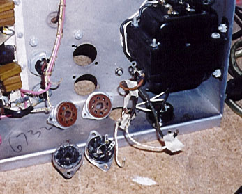
The next photo shows the chassis after I had removed both rectifier sockets.
The replacement sockets are also shown.
In the previous photo, the large transformer
to the right of the socket holes is not the main power transformer. It is
an auxiliary power transformer supplying DC voltage for the radio's drive motors
and relays.
With new rectifier sockets in place, the sizzling problem had disappeared, but
another one now appeared. When I powered the set up again, smoke and a crackling
sound came from the power transformer.
A little testing showed that the transformer had an internal short. Ouch!
The power transformer is often the most expensive component in a radio, and
this one would be difficult to replace. It supplies three separate filament
voltages in addition to the radio's high-voltage B+ supply.
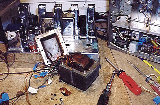
The next photo shows the transformer out of the chassis, with one
of the casings removed. A sorry sight, indeed!
Replacing the Power Transformer
If you ever "smoke" a transformer, you won't forget the
distinctive, sharp odor of burning varnish.
Luckily, I obtained a replacement transformer from fellow collector
Walt Heskes. The new transformer's specifications were almost
the same as the original, except that the B+ supply was somewhat
lower.
Not knowing how well it would work, I first connected the transformer with
temporary leads. To my delight, the radio performed beautifully despite
somewhat lower plate voltage on the audio output tubes. I decided to mount
it permanently, using a couple of spacers and handmade brackets to adapt
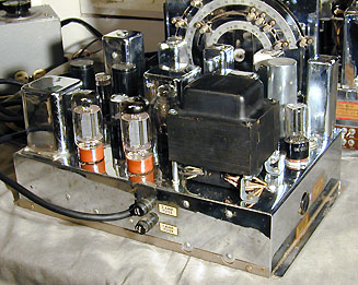
it to the chassis without making any new holes. The next photo shows the
new transformer in place on the power chassis.
A Scott purist would see at a glance that the transformer has been replaced, but
I doubt that most other people would notice. Another option would have been to
send the original transformer to a specialist to be hand-rewound, but the cost of that
would have exceeded what I paid for the entire radio! I have saved the old transformer
just in case I or a future owner decide to invest in rewinding later on.
The original transformer supplied 390 volts of B+ current, while the replacement
supplied only 310 volts. This translated to a deficit of about 90 volts at the
plates of the audio output tubes. The schematic calls for 340 volts at those points,
but I measured only about 250 volts using the new transformer.
To test whether
the lower voltage really mattered, I cranked up the line voltage on my variac
as high as it would go. This increased the plate voltage to about 300 volts.
The radio didn't seem to perform any differently at the higher voltage. In both
cases, it had excellent sensitivity, tone, and volume. Concluding that the
lower voltage made no difference, I decided not to make any further modifications
to increase the B+ level.
With a new transformer in place, my project was almost complete.
The next photo shows the underside of the tuner chassis.
Tasks Left Undone
Visible at several spots underneath this chassis are rectangular, metal-cased "bathtub" style capacitors.
At the time of this restoration, I was told that these
are oil-filled capacitors, expensive and very reliable units
that are more often seen in military-grade equipment. Since
the radio was operating well, I decided not to replace
them. As I learned when restoring my second 800-B (see below),
this advice was not correct.
I also decided not to disassemble and clean the motorized tuning assembly on the rear of the tuner chassis.
The service manual explains how to do this, but after lubrication
my motorized tuner worked just fine, so I stopped there.
The next photo
shows the large rectangular assembly on the back of the tuner which allows
you to adjust the tuning presets. Check out that chrome!
Inside the large, rectangular chrome housing at the rear is the round plate that makes the motorized
tuner work. The drive motor is mounted near the front of the chassis, near the tuning knob. If you look
closely at the chassis underside view, the motor is visible near center right.
800-B Versions
Stamped on the back of the metal tuner plate
is the date February 7, 1947. There were two versions of this radio, the
original 800-B and a revised model 800-B6. Mine is an 800-B6 and I believe this later version
is more common.
The revisions provided more flexibility in programming the automatic tuning pushbuttons.
They also reduced 60-cycle AC line "hum" in the receiver's audio.
In early sets, the 0D3/VR150 voltage regulator tube is located next to the pair
of rectifier tubes on the power/audio chassis. In later sets, that position is occupied
by a tall metal-cased capacitor and the voltage regulator tube has been moved to the
center of the chassis, next to the 6SL7 inverter tube.
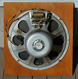
An Authentic Speaker
One year after buying my 800-B, I finally located an original 15-inch coaxial speaker, shown below.
My "new old" speaker sounds good, and would sound
even better with a good enclosure. Maybe I'll get around
to building one some day. Meanwhile, the Scott is serving
as the world's greatest shop radio, and I listen to it just about every day.
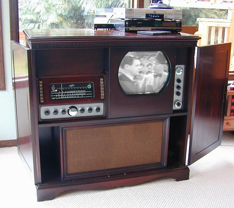
One good Scott deserves another . . . . Two years after getting my first 800B, I found another
one in a cabinet with a record changer and television. A photo appears below. See Scott 800B6 TV/Radio/Phono
for details.
|