Hallicrafters Model SX-88 Communications Receiver (1954)


 Owners Manual
QST Review
Owners Manual
QST Review
What's the finest Hallicrafters radio ever made? Some folks would say it is this,
the 1954 Model SX-88. Highly coveted by collectors, this impressive general-coverage
receiver uses twenty tubes and weighs in at around 75 pounds, making it the heaviest radio
in my entire collection and probably the most sophisticated.
With push-pull audio and a host of power features, the SX-88 was aimed
at high-end customers and priced accordingly, at a breathtaking $595.00.
It was manufactured for only two years, 1954 and 1955. Not surprisingly, given the
lofty price and short manufacturing run, fewer than one hundred of these radios are known to survive today.
I was fortunate to find this example in 1998. (No, I did not find it for $20 at a thrift store!
This set was purchased from a fellow collector and for once in my life I broke down
and "paid retail.")
The following photos show the radio shortly
after I acquired it. Click the thumbnail pictures to see larger views.
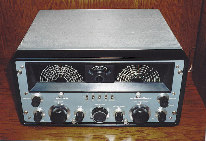
Similar to the SX-42 and other Hallicrafters sets, the SX-88
has a painted front panel with slightly raised lettering. The heavy metal bezel surrounding
the dials is not so typical and gives the radio a dramatic appearance. The cabinet top is
hinged, giving easy access for replacing dial lamps or tubes.
This is a continuous-coverage ("all wave") receiver, covering all frequencies from
535 khz to 33 mhz in six bands. Both tuning knobs are gear-driven and weighted with heavy
flywheels. Small chrome-plated locks are located next to each tuning knob. The centrally-located
bandswitch uses a stout drive belt and takes more muscle to move than on many radios. In addition to the
switch elements themselves, the bandswitch controls the moving pilot lamps behind each dial.
The distinctive half-round dials remind me of big jolly eyes. The next photo shows the
main tuning dial.
The dial lighting is best appreciated in a dimly-lit room. When you change bands, the
lamps move behind the dial to illuminate only the band in use. The S-meter in the
center is lit at all times, of course. Since bandspread is not needed for the
standard broadcast band, the right bandspread dial is not lit when you switch to BC
reception.
(Mis)adventure on the High Seas
Sponsoring expeditions to exotic locales was a favorite Hallicrafters advertising theme.
(See our SX-42 page for information about the
1946 Gatti-Hallicrafters expedition to "the Mountains of the Moon in deepest Africa.")
As Hallicrafters' top-line receiver, the SX-88 was heavily promoted in print.
In 1954, the company supplied SX-88 receivers and HT-20 transmitters
for the "Clipperton Island DXpedition" to the Pacific,
highlighting Hallicrafters long-distance communications equipment.
The Clipperton expedition got off to a rocky start. This account
appeared in the April 24, 1954 Chicago Daily Tribune:
Iowa Radio 'Hams' Reach Destination, Uninhabited Isle.
Five radio
amateurs who left Newton, Ia., March 18 reached the uninhabited island of
Clipperton in the Pacific Ocean yesterday, and reported their arrival to
radio "hams" of the Chicago area.
The group reached Clipperton Island, 600 miles
southwest of Acapulco, Mexico, after a hazardous voyage in which they
lost their sextant, then had their schooner virtually disabled through
loss of sails in a squall and mechanical troubles, and finally got caught
in the Humboldt current and drifted 90 miles from the island.
The Hallicrafters company of Chicago said the
group reported it was towed to the island by the Mexican coast guard . . . .
|
Given the loss of their sails and navigational equipment, it's lucky that the
hams had decent radios on board!
Despite this inauspicious beginning, the five intrepid radiomen pitched camp on
the island and eventually made 1108 contacts from 28 countries and
5 continents.
The next quote comes from a Hallicrafters ad published after the expedition:
Here is an adventure in the highest tradition—an exploit that opened the eyes
of the world to the tremendous potential and present value of amateur radio!
Few incidents in recent history have so caught the public fancy as this hazardous
landing on a remote speck of an island in the Pacific. The final success of the
project reflects great credit on every member of the amateur fraternity.
Hallicrafters is proud of its part in providing equipment for this worthwhile
project. But the real credit, the glory, if you like, goes to the gallant
crew that put out a good signal from Clipperton Island.
|
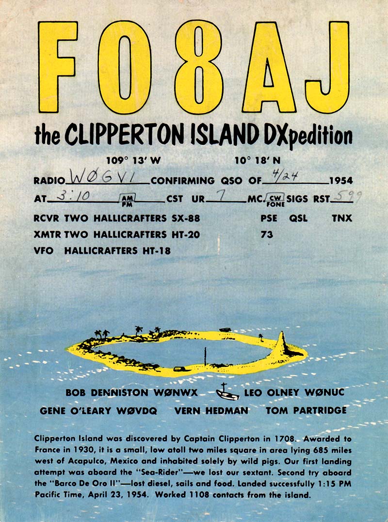
The QSL cards sent to confirm contact with the expedition are quite charming,
showing a drawing of the island atoll. The cards list the names of the five
adventurers—Bob Denniston WQNWX, Leo Olney W0NUC, Gene O'Leary W0VDQ,
Vern Hedman, and Tom Partridge—and provide these further details of the landing:
|
Clipperton Island was discovered by Captain Clipperton
in 1708. Awarded to France in 1930, it is a small, low atoll two miles square
lying 685 miles west of Acapulco, Mexico and inhabited solely by wild pigs.
Our first landing attempt was aboard the "Sea-Rider"—we lost our sextant.
Second try aboard the "Barco De Oro II"—lost diesel, sails and food.
Landed successfully 1:15 P.M. Pacific Time, April 23, 1954. Worked 1108
contacts from the island.
|
About two years after I wrote this web article, fellow boatanchor enthusiast
Ed Cleary sent me a scan of his QSL card from FO8AJ (see below).
The card is a great little piece of memorabilia. I printed out a life-size
version on high-quality paper and put it in a little frame next to my SX-88.
Description
Describing this complex radio is quite an enterprise.
Rather than paraphrase, I have reproduced the first four sections of the original
SX-88 Owner's Manual on a separate page. The manual gives many details and
describes the receiver's operation.
Another page reproduces a contemporaneous product review from June, 1954 QST magazine.
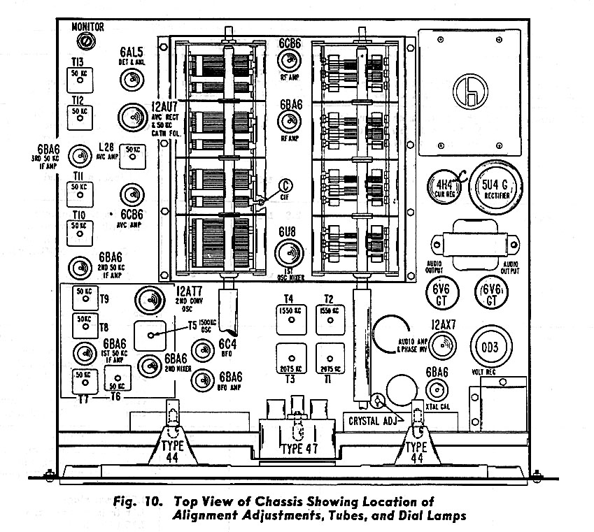
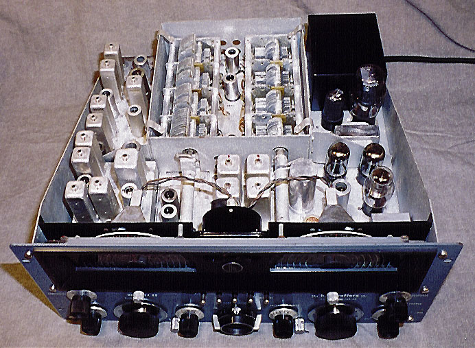
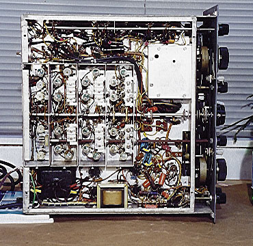
The next photo shows my receiver from above. The chassis has been removed from the cabinet
for restoration. The cover has also been removed from the tuner section, exposing
the large tuning capacitors. Next to the photo is the corresponding diagram from
the SX-88 technical manual. The diagram shows the tube layout and identifies the
50-khz, 1550-khz, and 2075-khz IF transformers.
Here is the lineup of the SX-88's twenty tubes:
| Tube |
Type |
Function |
| V1 |
6CB6 |
1st RF amplifier |
| V2 |
6BA6 |
2nd RF amplifier |
| V3 |
6U8 |
1st Oscillator/Mixer |
| V4 |
6BA6 |
2nd Mixer |
| V5 |
12AT7 |
2nd conv. oscillator |
| V6 |
6BA6 |
1st 50 KC IF amplifier |
| V7 |
6BA6 |
2nd 50 KC IF amplifier |
| V8 |
6BA6 |
3rd 50 KC IF amplifier |
| V9 |
6AL5 |
Detector/ANL |
| V10 |
6CB6 |
AVC amplifier |
| V11 |
12AU7 |
AVC rectifier/50 KC cathode follower |
| V12 |
12AX7 |
Audio amplifier/Phase inverter |
| V13 |
6V6GT |
Audio output |
| V14 |
6V6GT |
Audio output |
| V15 |
6C5 |
BFO |
| V16 |
6BA6 |
BFO amplifier |
| V17 |
5U4G |
Rectifier |
| V18 |
0D3 |
Voltage regulator |
| V19 |
4H4C* |
Current regulator |
| V20 |
6BA6 |
Crystal calibrator |
*Although some literature specifies a 4H4 tube, Hallicrafters Addendum
Sheet 94X1351 states that a 4H4C tube must be used. 4H4C ballast tubes are
virtually unobtainable at this time. Fortunately, you can substitute the readily-available
6V6 tube. The 6V6 provides no current regulation, but it has the right filament
characteristics and requires no modification to the receiver. The purpose of
the 4H4C current regulator was to help maintain stability when the AC power supply varied,
a problem that has largely disappeared in modern times. You should experience
no significant performance difference using a 6V6 in place of the 4H4C and the
6V6 will also last longer.
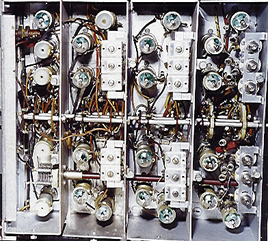
Directly under the big tuning capacitors you will find a swarm of coils, as seen in the
next picture. The receiver's bottom RF shield has been removed for the photo. Ceramic
coil forms indicate high quality (and high cost!).
You can find the complete SX-88 technical manual and schematic diagrams
at ftp://bama.sbc.edu/downloads/hallicra/sx88/.
Restoration Notes
My SX-88 had been cosmetically restored when I acquired it. In appearance,
it's as close to brand-new as one could want. The previous owner had also
installed a new band selector drive belt, a finicky and time-consuming task.
The receiver performed quite well as found. I wanted to make it reliable for
everyday service, however, which meant replacing some old capacitors and aligning
the receiver. Before replacing anything, I cleaned the entire radio very carefully,
using a spray contact cleaner inside components such as the volume control. I also
tested all 20 tubes and replaced a couple that were weak.
Replacing Capacitors
Replacing old capacitors is a routine
procedure that you can read about elsewhere in this website. Unlike my SX-42, this set did not have any of the notoriously unreliable paper
capacitors. Instead, it had "black beauties," which are essentially paper
capacitors in a plastic shell, and every bit as bad.
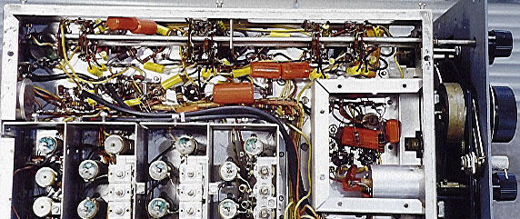
When I reviewed the parts list, I counted about fifty capacitors needing replacement. Quite
a chore! The next photo shows the radio about one-fourth of the way through the recapping
process. You can see orange and yellow replacement capacitors near the bottom right.
At the top of the receiver is a dense forest of black beauties, surrounding the large
variable selectivity switch.
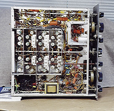
The following photo shows the chassis after recapping was finished.
You can see a lot more yellow and orange at the top.
Although the radio played with no hum, I also replaced the three electrolytic
filter capacitors in the power supply. Old filter capacitors fail quite often
and I wanted to make this radio trouble-free. You can see the blue cases of the
new filter caps in the previous picture.
The SX-88's power supply is unusually complex.
In addition to a 5U4GB rectifier tube, you will find a 0D3 voltage regulator
and 4H4C current regulator to ensure maximum stability.
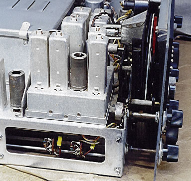
This receiver has six levels of selectivity, a great feature for pulling in
weak and distant signals. Implementing the feature requires a lot of components, however.
The next photo shows the crowded area around the variable selectivity switch.
The multi-element switch stretches from front to back of the chassis. (Its knob is visible
at upper right.) Replacing all of the capacitors on and around the delicate switch wafers
took me quite a while.
The small square cage at lower right in the previous photo contains the Pitch Control,
used to vary the frequency of the BFO (beat frequency oscillator) when
receiving CW and single-sideband signals. The cover of this cage was
removed for this photo. Also visible, to the right of the cage, is the
heavy flywheel of the main tuning knob.
Components for the second converter are mounted in a small sub-chassis that sits atop the
main chassis:
Replacing the three "black beauty" capacitors in this sub-chassis
requires disconnecting other components under the main chassis.
Aligning the Receiver
The last restoration step was to realign the receiver. A precision radio such as the SX-88 would
not be expected to drift seriously out of alignment in normal use. You never know who may have
tinkered with the alignment in the past, however. I also had replaced many capacitors
and a few resistors in the variable selectivity circuits, so I figured that the alignment should
at least be checked.
The second IF (intermediate-frequency) stage operates on 50 kilohertz, an unusually low frequency.
Most radios use a higher frequency, such as 455 khz. This posed a practical obstacle. Like many
standard signal generators, my trusty old Eico 324 can't generate such
a low frequency.
Posing this question to the rec.antiques.radio+phono newsgroup
generated a variety of interesting and useful responses. Several folks pointed out that
an audio generator would do the trick. Others suggested using the output of the radio's
own BFO circuit, or even building a simple solid-state circuit to generate the desired frequency.
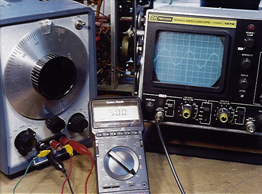
I happened to run across a nice old HP 200CD audio generator around this time, so
I bought it to complete this project. The next photo shows the audio generator hooked up to my
digital multimeter (used in frequency counter mode) and oscilloscope. On the left
is the audio generator with its large frequency dial. The digital meter
shows that the generator is set to exactly 50.0 khz and the 'scope shows
that the HP produces a nice clean sine wave.
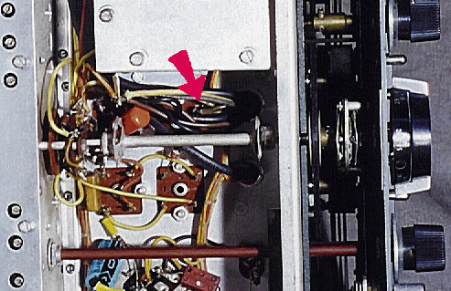
To perform the 50 khz alignment, you must disconnect the output lead from
transformer T3. This disconnects the RF amplifier and first mixer stages, allowing
you to inject the signal upstream of the 50-khz IF stage. This particular lead
is quite difficult to access, being located underneath a thick clump of cables.
The next photo shows the lead in question (the red arrow marks the spot).
To unsolder this lead without melting everything in vicinity, I temporarily tied some of
the cables out of the way and held others aside with a spring tweezers.
This allowed me to snake a thin soldering pencil under the shaft of the bandswitch
with one hand while the other hand slipped a thin pliers in between the cables
to grasp the loosened lead. To avoid slipping connections during alignment, I then
soldered a temporary wire onto the lead which I could connect to the audio generator's output.
The SX-88 technical manual says that you should maintain an approximately 1-volt reading
on the meter while adjusting the 50 khz IFs. This sounds simple enough, but when I connected
the generator and powered everything up, I measured about -50 volts at the designated test point!
Quickly powering down, I rechecked all my connections and tried it again. Same result.
Well, perhaps the manual is wrong. Let's give it a try and see what happens.
I quickly determined that the alignment wouldn't work with such a strong signal. Cautiously
turning one of the IFs produced no measurable change at the test point.
Perhaps the generator was swamping the receiver. On the other hand, perhaps there was something
wrong with the receiver in the circuits being tested. I decided to find out what voltage
was present at the test point during normal operation. This meant disconnecting my temporary
lead and reconnecting the output lead to transformer T3. In normal use, I measured anywhere
from -1 to -3 volts at the test point. A small negative voltage would be normal at this spot
(the load resistor of the detector tube), which suggested that the generator's output was
indeed too strong.
A newsgroup member suggested using a potentiometer to attenuate (reduce) the generator's output.
I also made contact with fellow collector Bruce Stock, who explained how to set up and use my
"new" HP 200CD generator while I waited for my mail-order manual to arrive.
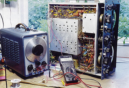
The next photo shows the generator, multimeter, and receiver set up for the alignment.
To attenuate the generator's output, I connected a potentiometer between the generator's
ground and signal leads and then took the signal from the pot's wiper. That kept the voltage
at the receiver's test point around -1 volt and I could still see measurable differences
when tweaking the IFs.
Adjusting the eight 50-khz IF transformers did not take long, once everything was finally
set up. None of them was drastically off, but they were not perfect, either, so I was glad
that I had gone to all this trouble. When I was finished, I reconnected the radio for normal
operation and gave it a quick road test. So far, so good. It performed well on all bands.
I put away the audio generator and hauled out my Eico signal generator to finish aligning
the 1550-khz and 2075-khz IFs. After that, I aligned the RF stages, another
exacting procedure involving about three dozen adjustments.
Time for the Pepsi Challenge!
Whew! Now it was time for the final road test, a "Pepsi challenge" between the SX-88 and
my previous shortwave champion, my SX-42. I powered up both receivers side by side and tuned them to
a number of different stations on all the bands, using the same antenna. To my delight,
the SX-88 blew away the SX-42. Don't get me wrong: the SX-42 is an outstanding
and well-engineered receiver. But the SX-88 outmatches it across the board.
After a long sojourn on my workbench, the SX-88 finally got to climb back into its case. If you
need to work on one of these beasts, be extremely cautious when removing and replacing the
chassis. It is very heavy and you must resist the temptation to grab the knobs for support.
One way to get the chassis into the cabinet is to sit down with the chassis face-forward
in your lap and have a helper slip the cabinet down over the rear of the chassis. There's not
much risk of dropping a radio that's sitting in your lap, but it can be a real
challenge to stand up with close to 100 pounds of boatanchor in your arms. There's also
a chance of breaking the dial glasses with your belt buckle! If you
are working alone, I recommend clearing a big space on your workbench and carefully
sliding the chassis into the cabinet.
Final Thoughts
With all work complete, I lugged the radio to our upstairs bedroom and placed it on
the small desk which serves as my bedside table. This favored listening position has
been occupied by many radios over the years, from my Zenith 3000-1
and various other TransOceanics, to Hammarlund receivers such
as my HQ-180AC, and Hallicrafters receivers including
the SX-42 and S-20R.
None of those radios can come close to the SX-88 in listening enjoyment, however.
Hooked up to a big Electrovoice speaker, it rivals my Fisher 800-B as
a high-fidelity BC receiver. In the shortwave bands, the BBC sounds like it is broadcasting in FM!
I especially like the SX-88's antenna trimmer. Once you have carefully tuned in a
station, it's fun to peak the signal with the trimmer and watch the S-meter climb still higher.
I think it will be a long time before anything knocks the '88 out of the coveted bedside spot.
After restoring this receiver, I couldn't resist staging a humorous tableau
next to the trash cans outside my workshop. Perhaps you will get a chuckle out of it.
No, you can be sure that I didn't just toss my SX-88 onto the ground next
to the cans. If you look closely, you'll see that it's sitting on a clean
piece of carpet and padded on its top with newspaper.
|