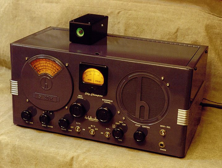
Hallicrafters Model S-20R Communications Receiver (1939)


This 65-year old Hallicrafters S-20R communications radio is a true classic.
I love its Machine Age design and the famous "h" logo on the metal speaker grille.
Introduced shortly before the US entered World War II, this radio must
have played many wartime broadcasts during those troubled years.
The first photo shows the set after restoration. It also shows my home-built magic
eye tuning indicator, which you can read about elsewhere.
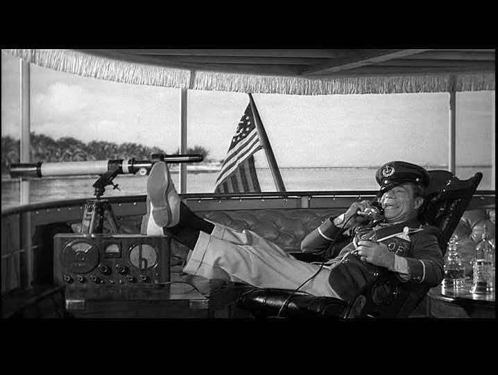
The S-20R makes an incongruous appearance in Some
Like It Hot, the hilarious 1959 comedy starring Marilyn Monroe, Tony Curtis, Jack Lemmon,
and Joe E. Brown. In this photo, we see Brown's character (Osgood Fielding III) on his
yacht, making a ship-to-shore telephone call to the hotel with his feet propped on an S-20R.
There are a couple of things wrong with this picture. First, the movie is set in 1929,
the year of the St. Valentine's Day mob massacre in Chicago, but the S-20R didn't debut
until 1939, ten years later. What's worse, the S-20R is a radio receiver, not a transmitter/receiver.
Osgood's telephone handset is plugged into the radio's headphone jack. So, he might have been
able to listen to the radio, but people on shore couldn't possibly have heard what
he said unless he had a really, really loud voice!
(For Hallicrafters trivia buffs, the company did manufacture marine radio telephones
during the years 1939-1945, but they looked nothing like this.)
Oh well, that's Hollywood! And it's still fun to see one of your radios in an old movie.
Description
The Hallicrafters S-20R Sky Champion was made from 1939-1945 and sold for $49.50, putting it in middle of the company's prewar radio lineup. The entry-level Hallicrafters set for 1939 was the model S-19 Sky Buddy, selling for $29.50. Higher priced prewar models included the SX-24 Skyrider Defiant at $69.50 and the SX-25 Super Defiant at $94.50.
Model S-20R was the first in a long-lived product line. Hallicrafters repackaged essentially the same radio, with minor updates, as models S-40 (1946-1955), S-85 (1955-1959), and S-108 (1959-1961). If you look at the photos of my S-40B, you will quickly see the resemblance.
This is a four-band receiver, covering all of the frequencies from 540 Khz to 44 Mhz. In addition to bandspread tuning, it features AVC (automatic volume control), ANL (automatic noise limiter), BFO (beat frequency oscillator), a three-position tone control, and a headphone jack.
The back panel contains sockets for two optional accessories. One socket is for power, permitting mobile use with batteries (one 6-volt and one 340-volt). The second socket is for an external S-meter to show signal strength while tuning. The S-meter socket came in handy for my magic eye project.
This was a pretty full-featured receiver for the price. The higher-priced SX models added only a few nice-but-not-necessary features: variable selectivity, a crystal filter, calibrated band spread, and a built-in S-meter.
As the following tube lineup shows, the S-20R has an RF amplifier and two stages of IF amplification.
| Tube |
Type |
Function |
| V1 |
6SK7 |
RF amplifier |
| V2 |
6K8 |
Mixer/oscillator |
| V3 |
6SK7 |
1st IF amplifier |
| V4 |
6SK7 |
2nd IF amplifier |
| V5 |
6SQ7 |
2nd detector/AVC/1st audio |
| V6 |
6F6G |
2nd audio amplifier |
| V7 |
6H6 |
Automatic noise limiter |
| V8 |
6J5GT |
Beat frequency oscillator |
| V9 |
80 |
Rectifier |
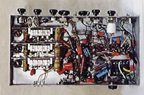
The next photos show the chassis.
The plastic dials on this radio were originally white with black lettering. Over time, the white plastic turned amber from exposure to light, becoming darker in areas that were exposed longest. You will see amber dials on most Hallicrafters receivers of this vintage, unless you find one that spent its life stored in a lightproof container.
I bought this set for $40 at a Seattle swap meet in the summer of 1999.
The cabinet was good except for a few minor paint scrapes and the usual
layers of grime. The seller stated that it "worked," but I
planned to restore the electronics in any case, so I only checked to
make sure that the chassis was complete and not visibly abused.
Electronic Restoration
Restoring the electronics began in a routine manner, but this radio had some problems that were not immediately apparent.
Before powering up the radio, I removed the chassis from the cabinet, cleaned it thoroughly, and checked each of the tubes. Then I connected an antenna and fired it up, using a variac to slowly increase the supply voltage. The radio played well during this short initial test, with reasonable sensitivity on the shortwave bands and good tone on the standard broadcast band.
The next phase involved replacing all of the old paper and electrolytic capacitors (see
Replacing Capacitors in Old Radios).
About midway through the recapping process, the primary electrolytic capacitor in the power supply blew out with a vengeance. I normally give the radio a brief test under power after each capacitor replacement, as a doublecheck against wiring mistakes. When the filter capacitor gave up the ghost, the radio suddenly started emitting a very loud hum that drowned out all reception. A couple of experiences like this taught me to
replace the filter capacitors first, then move on to the smaller
capacitors.
After replacing the filter capacitors, the radio began to play normally again. By the time I had replaced the last paper capacitor, however, it had developed a loud, intermittent crackle.
The crackle was not affected at all by the volume control. That is, the explosive noise was equally loud whether the volume was turned down or up. This clue suggested that the problem lay somewhere downstream of the volume control, which narrowed the number of places to look.
In this radio, the 6SQ7 tube provides the first stage of audio amplification, as well as AVC, and the 6F6 tube serves as the final audio amplifier. The problem must have been located in those tubes' circuits.
Seeking advice from the rec.antiques.radio+phono newsgroup, I got some great tips for troubleshooting noise problems in general.
Bill Turner suggested a simple test for this particular case: pull out the 6SQ7 and 6F6 tubes one at a time and note the results.
With the 6SQ7 tube out of the set, the radio's signal disappeared but the crackle continued unchanged. With the 6SQ7 back in place but the 6F6 tube removed, nothing could be heard. This test indicated that the problem must be in the 6SQ7's circuitry. (Again, the 6SQ7 serves as the first audio amplifier as well as the AVC control.)
In the course of troubleshooting the crackle, I had already replaced all of the small components around the 6SQ7 and 6F6 tubes, resoldered all of their connections, and thoroughly cleaned their tube sockets and neighboring circuitry. That seemed to leave only one villain—the 6SQ7 tube socket itself.
Although sockets tend to be very reliable, it is possible for voltage to arc between two pins of the socket. This can occur where dirt between pins offers an initial path. As arcing continues to occur, carbon builds up along the path, creating a condition that slowly grows worse.
The most practical cure for an arcing socket is to replace it with a new one. The next photo shows the 6SQ7's circuitry before the replacement.
Fortunately, the 6SQ7 is located in an uncluttered part of the chassis, making removal a straightforward job. The socket is attached by two rivets which go through the chassis. After removing all components from the socket, I drilled off the expanded bottom of each rivet. This allowed me to remove the socket from underneath.
If you need to drill out socket rivets, it's a good idea to keep a small magnet and vacuum cleaner nearby and clean up the metal dust as you work. Loose metal filings can cause nasty problems if they work their way inside a radio's electromechanical components.
The rivets did not simply fall out of the chassis after their bottoms were drilled off. My not-very-sharp drill bit had slightly expanded the rivet shafts where they met the chassis underside, causing them to stick securely. Cautious tapping with a metal punch from underneath didn't budge them a bit.
To work them loose, I turned the chassis over and used a Dremel Moto-Tool with cutting disc to form a slot in each rivet head. The slots allowed me to turn the rivets with a screwdriver. Turning loosened the rivets enough that I was able to carefully wedge a knife blade between each head and the chassis top. Gently working a thin screwdriver blade into the gap between rivet head and chassis, I was finally able to remove these tiny but stubborn bits of metal from the holes.
That sounds like a lot of hassle, and it was. In hindsight, it would have been simpler to use a drill bit exactly the same diameter as the rivet shaft and drill it out completely in the first place. I didn't happen to have a drill bit that size, however, and my method eventually did the job. The next photo shows the chassis after the socket was removed.
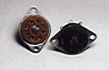
Another photo shows the new socket on the left and the old socket on the right.
I installed the new socket using a stainless steel screw and locking nut, with "star" locking washers on both sides of the chassis. When replacing a socket, you should tighten the mounting screws very well, to prevent any problems with intermittent ground connections in the future.
To my relief, the radio played normally after surgery—at least for a few minutes. Before long, however, yet another component gave up the ghost. To the left of the 6SQ7 tube in the previous chassis photos, you can see two large brown resistors. These are marked R31 and R32 on the schematic and they are part of the radio's power supply.
R32 failed dramatically, overheating and starting to smoke. I quickly powered the radio down and disconnected that resistor. I also checked R31 and discovered that its value was far out of spec. The schematic specifies 10K for this resistor, but its value had drifted upward to 30K. I replaced both resistors with good ones from my stock of spares, using higher-wattage units for an extra margin of safety.
The next photo shows the new socket and new resistors in place.
After those replacements, the radio played with no crackle. The operating voltages also tested correctly throughout the set, indicating a healthy power supply.
The last step was to align the radio using my signal generator and multimeter. Alignment is described in my Zenith 6-J-230 restoration article. The next photo shows the chassis underside after restoration.
Cabinet Restoration
The S-20R has a painted steel cabinet, bluish gray in color, with white lettering on the front panel. My cabinet was in average shape when purchased, as shown in the following photo.
The worst cabinet blemishes were on the front. Many small chips had been scraped off the bottom of the front panel. There was a worn area on the bottom of the main tuning dial cover, under the embossed S-20R logo, and assorted small scratches elsewhere.
Someone had also stuck a Dymo inventory label on the front. Putting the cabinet out in the sun for a while softened the label glue, allowing me to gently peel it off. A little paint thinner on a Q-tip cleaned up the remaining sticker glue.
The next photo shows the cabinet ready for refinishing. At this point, I had carefully cleaned the entire cabinet and removed any rust from scratched areas.
The decorative aluminum trim panels were removed and polished with Mother's Mag & Chrome Polish. Then I sprayed on a light coat of clear finish to prevent tarnishing.
Since I had not done much cabinet painting, I decided that this low-cost radio would be a good one to practice on. To get paint of the right color, I brought the cabinet to a local auto paint supplier. They used computerized color matching to mix a pint of the right color and put it in a spray can.
Before doing any painting, I disassembled the cabinet and carefully sanded all chipped and scratched areas.
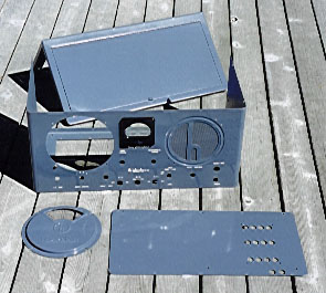
The S-20R cabinet comes apart in four pieces. One piece forms the front panel and sides. A second circular piece with the S-20R logo is held inside the front panel with screws, covering the main tuning dial. A third piece forms the back and top, with a hinged cover. The fourth piece is the case bottom, with rows of access holes for aligning the receiver.
The next photo shows all four pieces after repainting.
The bottom and back/top pieces were easy to paint, since I could spray the whole piece at once. The next photo shows the back/top piece after applying the first of a few coats of paint.
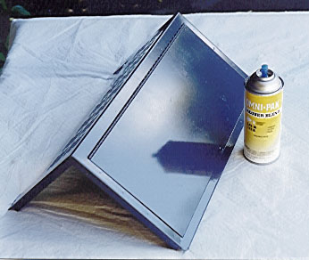
Touching up the front pieces required much more work. The next photo shows how I masked off all but a thin strip at the bottom of the front panel.
The mask allowed me to paint only the chipped zone, leaving the rest of the front panel untouched. The following photo shows the painting in progress.
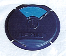
The circular dial cover got a similar treatment. The next photo shows how I masked off most of the dial with plastic, to build up a few layers of paint over the worn area at the bottom.

After applying the initial coats, I removed the masking and covered the plastic dial window with blue masking tape. I used a small nail scissors to cut pieces of tape to fit the window exactly. I also masked the back of the plastic window, to make absolutely sure that no paint could get onto it.
Then I wet-sanded the area where I had applied the initial coats, to blend the edge of that area with the main cover body. I used #600 grade paper. You can see the results of the sanding near the bottom.
I then applied three top coats to the cover, sanding the entire cover between coats to ensure a smooth finish.
The next step was to carefully sand the edges of the front panel, smoothing the slight edge between the new paint and the old. This was a long, fussy process. In hindsight, it might have been better to touch up the chips with a small brush. Although spraying took less time than hand brushing, it also left behind a straight line between the old paint and the new. On this high-gloss cabinet, a straight line tends to catch the eye more than an irregular shape. It took quite a bit of work to erase that line and blend it with the old paint.
I also had overestimated the difficulty of doing a good touch-up job with a brush. After removing the mask, I noticed a few chips around the top of the front panel. Fixing these with an brush did not take much time and the result required almost no sanding. The next time that I have a cabinet with small chips around the edge, I'll start with a brush!
After carefully sanding the painted edge, I used Novus Plastic Polish #2, a very fine abrasive polish, to buff the repaired area to a glossy sheen. You can use other abrasives for this step. Some folks use successively finer grades of paper (#800, #1200, etc.), others use auto paint rubbing compound, and so on.
When the buffing was complete, I went back over the entire cabinet with Novus Plastic Polish #2 to ensure an absolutely consistent, shiny finish.
Assembly and Alignment
At this point, I was ready to put the chassis back in the cabinet. As often happens, however, one tiny part slowed me down. When I got out the four screws that hold on the metal dial cover, I noticed that one looked badly stripped. Perhaps it was stripped at the factory. In any case, this meant a trip to the hardware store. The store had nothing with exactly the same knurled head as the original screws, so I chose some nice stainless screws that looked as similar as possible. The same type of screw is used to attach the speaker. To avoid a mismatched look, I replaced all of those, too.
With the chassis finally back in its restored cabinet, I was able to finish aligning the receiver, making sure that the dials tracked correctly against the hairlines in the plastic dial windows.
Adding a Magic Eye Tuner
After restoring the radio, I went on to build an external "magic eye" tuning indicator that plugs into an accessory socket in back of the radio. If you own an S-20R, you may enjoy building one yourself. See: Adding a Magic Eye to a Hallicrafters S-20R.
Final Thoughts
This radio presents a good case study in how a "working" radio may actually need a lot of restoration. Yes, it played reasonably well when I brought it home. But virtually all of its small paper capacitors were leaky. One of its electrolytic capacitors failed dramatically after roughly one hour of play. Two critical power-supply resistors were defective. And several other small components around the 6SQ7 and 6F6 tubes were bad enough to merit replacement.
The lesson is simple. An unrestored antique radio may seem to play well—and many do—but it's only a matter of time before some tired component fails. When that happens, you may be facing worse problems than if you had performed a routine overhaul in the first place.
|