|

Adding a Magic Eye to a Hallicrafters S-20R


I have always been enchanted by magic eye tuning indicators. Who can resist a green glowing eye that "winks" as you tune in a station? Apart from the charm factor, a magic eye is very sensitive and responds faster than a needle-type meter.
The Hallicrafters S-20R is a fine old shortwave receiver, but it lacks a tuning indicator.
Hallicrafters did offer an external S-meter that plugged into a socket in the back, but the external meter
was an extra-cost option (model SM-20) and probably quite scarce nowadays. The alternative is
to roll your own, and that's what I did, choosing a magic eye over the more pedestrian S-meter.
This page gives complete plans for building your own S-20R magic eye. The eye tube is contained in a
small box that connects to the receiver with a cable. With a little creativity,
this project could be adapted to many different radios.
The following photos show the magic eye in action. Click the small thumbnail photos to see larger views.
Caution! Although the magic eye circuit is simple, this project requires connecting
to a high-voltage current source within the chassis of an antique tube radio. For that reason,
I consider it suitable only for advanced builders and radio restorers. The project also
requires the ability to read your receiver's schematic and determine the appropriate place
to connect to its AVC bus. If you are not able to build this project safely, please find
a technical helper who can do so.
Parts for the Magic Eye
The parts for this project are readily available. Here is what I used.
|
Part |
Description |
Part No. |
Quantity |
|
V1 |
1629 eye tube |
AES |
1 |
|
C1, C2 |
470uf 16v electrolytic capacitor |
Radio Shack 272-957 |
2 |
|
SR1, SR2 |
1N4001 rectifier diode |
Radio Shack 276-1101 |
2 |
|
R1 |
1 megohm 1/2 watt resistor |
Radio Shack 271-1134 |
1 |
|
R2, R3 |
10 megohm 1/2 watt resistor |
* |
2 |
|
Misc |
Plastic project box, 5" x 2.5" x 2" |
Radio Shack 270-1803 |
1 |
|
Misc |
Octal tube socket |
AES P-ST8-209MIP |
1 |
|
Misc |
Hookup wire |
Radio Shack |
1 |
|
Misc |
Flexible cable sheath |
|
1 |
|
Misc |
Aluminum coax clamps |
|
2 |
|
Misc |
Strain relief clamps |
|
2 |
* I could not find a mail-order source that sells only a couple of 10-megohm resistors at a reasonable price. If you don't happen to have any on hand, you may need to buy a kit (i.e., assortment of values) that includes the needed resistors. You can also wire two or more smaller resistors in series to obtain the desired value. For instance, two 5-megohm resistors connected in series equal one 10-megohm unit.
The part numbers given above may change, of course. Please consult the suppliers' latest catalogs. AES stands for Antique Electronic Supply.
You are free to substitute equivalent parts and use a different enclosure. I chose a plastic enclosure for safety reasons. One of the wires to the magic eye tube carries B+ voltage, which runs over 250 volts in my S-20R. That kind of voltage can deliver a bad shock, so don't take any construction shortcuts that might create a shock risk.
I used the smallest enclosure that would contain the eye tube and its circuitry. A somewhat larger box would make the project easier to construct, giving more room to wire the small components onto the tube base.
Magic Eye Schematic
After acquiring the parts, you should print out the Magic Eye Schematic.
The schematic is formatted to print on a single 8.5 x 11 inch page and it includes the parts list for convenience.
For best results, do not print the schematic from your web browser. The browser normally
adds margins and header/footer information that may cause the printout to be clipped
or split onto two pages. For Windows users, click anywhere on the schematic image
with your right mouse button, then choose Save As from the popup menu. Save the image file magiceye.gif
to a convenient place on your hard drive. Then load magiceye.gif into a paint program such as PhotoShop
and print from that program.
Building the Magic Eye
Here are the steps that I followed in building this project.
-
Wire small components and cable wires to octal tube socket.
-
Connect jumper from receiver's AVC bus to pin 3 of S-meter accessory socket.
-
Test magic eye for correct operation.
-
Install magic eye in project box.
-
Attach cable sheath and plug.
Step 1. Wire small components and cable wires to octal tube socket.
I found it simplest to mount the small components directly on the eye tube socket. The result
is very compact, as the next photo shows.

I wired the components onto the tube socket in two stages. First, I connected
the three resistors, R1, R2, and R3. Then I soldered together the capacitors and rectifiers
(C1, C2, SR1, SR2) as a little subassembly and connected that to the socket.
Start by soldering resistor R1, a 1-megohm unit, directly between pins
3 and 4 of the socket.
At pin 4, where R1 is attached, you will also connect the cable wire that will run to
the B+ voltage pin of the accessory socket. The cable length is not critical; I
made mine about two feet long, allowing the magic eye to be placed either atop
the receiver or on the side.
I recommend using different colored wires to
minimize confusion when you later wire a plug the cable's end. For instance, you
could use red for the high-voltage B+ wire, black for the Ground cable,
green for the 6.3-volt filament wire, and yellow for the AVC bus wire.
After attaching resistor R1 and the first cable wire, solder together resistors R2 and R3.
These resistors form a voltage divider to reduce the S-20R's AVC bus voltage to the right
level for this tube.
The junction of the R2/R3 resistor pair is wired to pin 5 of the socket. The "far"
end of R2 is connected to pin 8, which also connects to Ground. The far end
of R3 is connected to the cable wire that will run to the AVC bus pin on the
receiver's accessory socket.
At this point, you have connected three resistors and two of the four cable wires,
forming the innermost "layer" of components attached to the socket.
Next, lay out the four voltage doubler components (C1, C2, SR1, SR2)
in a square arrangement on your workbench. The width of the square formed by these
four components should be roughly the same as the diameter of the tube base.
The idea is to make a little subassembly that can be neatly attached right behind
the socket.
The voltage doubler components are polarity-sensitive,
so make sure that their positive and negative ends are arranged as shown in the
schematic. Solder together these four components, keeping in mind that
each corner of the resulting square will be an attachment point for some other
part of the magic eye circuit.
Hold the completed voltage doubler subassembly up to the socket and determine
which way it should be mounted to form the shortest and tightest connections
to the tube base. Then connect the voltage doubler to the magic eye as follows:
-
The junction of C1 and SR1 connects to pin 2 of the magic eye socket.
-
The junction of C2 and SR1 connects to pin 7 of the magic eye socket.
-
The junction of C1 and C2 connects to pin 8. Also connect the cable wire that will run to the Ground connection at the receiver's accessory socket.
-
The junction of SR1 and SR2 connects to the cable wire that will run to the 6.3-volt filament connection at the receiver's accessory socket.
The magic eye circuit is complete! Before going any further, doublecheck all of your
connections against the schematic and examine your solder joints to make sure that
they are clean and solid.
Step 2. Connect jumper from receiver's AVC bus to pin 3 of S-meter accessory socket.
At this point, your magic eye should be operational, given the right connections to the receiver.
Although you could wire its cable permanently to the chassis, I chose to use a plug
that fits the radio's S-meter accessory socket. This lets you disconnect the magic
eye when moving or servicing the receiver.
Whether or not you use a plug, the S-20R's accessory socket provides three of the four
connection points that you need. Like the factory S-meter, our magic eye needs
connections to Ground, the B+ voltage supply, and the 6.3-volt filament supply.
It also requires a fourth connection to the receiver's AVC bus.
Pin 3 of the S-meter accessory socket is not normally used, so you will need to
connect a short jumper wire from this pin to the receiver's AVC bus. Again, I am
going to assume that you are an advanced builder who can refer to the S-20R
schematic and determine the right connection point on your own. If you don't have
a schematic, one can be ordered from the sources listed on our Parts
page.
You will need to remove the radio's bottom access panel for Steps 2 and 3.
It it not necessary to remove the S-20R's chassis from its cabinet.
Step 3. Test magic eye for correct operation.
With AVC voltage available at pin 3, you can connect the cable
wires to the receiver and test your magic eye. I temporarily
soldered the cable wires to the accessory socket terminals inside
the receiver. Needless to say, this should be done with the receiver
unplugged! (Please don't succumb to the temptation to connect the cable
wires with alligator clips. The risk of short circuits or shocks is not
worth the negligible time saving over making temporary solder joints.)
Before turning on the receiver, doublecheck your connections
and secure the cables and magic eye on your workbench so that nothing can
slip around or make a short circuit while the receiver is powered.
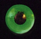
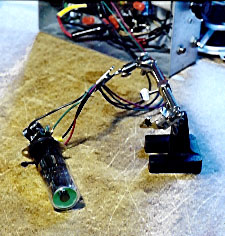
The next photo shows the author's prototype during its bench test.
The eye tube glows green and is fully closed.

A correctly functioning eye tube should close completely when you tune in a strong
local station. When the receiver is tuned between stations (no signal), it
should open so that a full quarter of the glowing area is dark. Weaker stations
should cause it to close partly. The closed portions should not overlap, even
on the strongest stations.
If your eye tube does not perform as expected, then you should power down the receiver and
check all of your work. Make sure that you have not reversed polarity on one of the capacitors
or rectifiers, connected a component to the wrong spot, etc.
While your eye is glowing, mark the tube base to indicate which side will face up in the box
when finally installed.
It is customary to install eye tubes with the closing portion facing down, as shown in Figure 1 later
in this article.
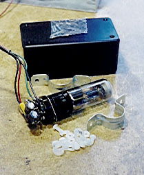
Step 4. Install magic eye in project box.
If your eye works acceptably, give yourself a pat on the back. The hardest part
of this project is over! The next step is to install the completed circuit in
the plastic box.
The eye will need an opening to peek though. Make a round hole about 7/16 inch in diameter in the front end of the box.
I used a cardboard insert from the 1629 tube's box as a template. The hole in the insert was slightly
smaller than the tube diameter—exactly the right size for the eyehole. If you want a fancier
look, you could fashion a metal rim for the eyehole or even attach a decorative eye hood salvaged
from a junker radio cabinet.
On the rear end of the box, make a hole about 1/4 inch in diameter for the cable wires.
The 1629 tube does not generate much heat, but I added a couple
of small holes in the box bottom and rear for ventilation.
Magic eye tubes are typically mounted with a single clamp around the tube base. I couldn't
find a screw-type clamp of the right size, so I improvised with a pair of half-round
clamps used for coax tubing. I had to bend the ends of the clamps to fit them inside
the narrow box.
The front clamp is held in the box by its own tension and supports the glass
portion of the tube. The ears of this clamp are bent downward.
On the rear clamp, I bent the ears upward so that I could run screws through each
side of the box. The tube base lies in the rear clamp. I fastened the tube base
to the rear support with a stout nylon tie.
You are free to improvise whatever tube mounts you like, of course. Just keep in mind
that the tube will need to be replaced some day!
Before finally installing the tube assembly, I put a rubber grommet inside the small
hole in the rear for the cable wires. Then I screwed a nylon strain relief clamp onto
the back of the box to secure the cable.
The next photograph shows the magic eye from the rear, with the strain relief clamp in
place.
With the magic eye securely installed inside, you can screw on the top of the box.
Step 5. Attach cable sheath and plug.
I provided extra protection for the cable wires by enclosing them in a length of vinyl
tubing. I had hoped to use some kind of dark fabric tubing that would
look more authentic, but the vinyl tubing was all that I could find locally. Because the
cable carries high voltage and is exposed to wear and tear outside the cabinet,
I feel strongly that it should be enclosed for protection.
To complete the project, you need to fashion a five-pin plug to fit the S-20R's accessory
socket. The base from a salvaged five-pin tube makes a perfect plug. I didn't have any dud five-pin tubes
lying around the workshop, but fellow collector Don Borowski kindly donated one to the
cause. Thanks, Don!
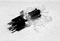
The next photo shows the five-pin tube after breaking its glass envelope. (This
tube already had a cracked glass, so I had no hesitation about recycling its base.)
Cover the tube with an old cloth and tap it smartly with a hammer to break the glass.

After breaking the glass envelope, use snippers to detach the tube elements from the
wires that connect to the pins in the tube base. Then remove any glass fragments remaining
around the inner rim of the base. Be careful not to wreck the delicate wires that
connect to the base pins. The next photo shows the tube base ready for connection
to the cable.

Your plug will need some kind of cap. You will also need to slip the cable wires through
the cap before soldering them to the plug.
The bottom of a plastic 35mm film canister will fit a salvaged tube base.
Use a craft knife to slice the bottom from the film canister, leaving a thin
lip around the edge.
Make a hole in the cap large enough to admit the cable wires.
Attach a nylon strain relief clamp to the cap. Slip the wires through
strain relief clamp and through the hole in the cap, then tighten the strain
relief clamp.
Now you are ready to solder the cable wires to the right pins in the plug base.
Follow the schematic carefully and test your connections with a multimeter. Use
thin "spaghetti" tubing to insulate the connections and
arrange the wires to fit comfortably when the cap is closed.
It's time for a final road test. Carefully slide the plug into the radio's
accessory socket, then power up the radio and check the eye. If it does not
perform correctly, power down the radio and check all of your connections against
the schematic.
The last step is to glue the cap
onto the top of the plug. I simply filled
the plug innards with hot glue and pressed the cap down.
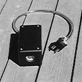
The next photo shows the completed magic eye installed in its box. The cable is turned
to show the strain relief on the plug cap.

How the Magic Eye Works
Although I own several radios with magic eyes, I had never paid much attention to how eye tubes work,
apart from noting that they respond to a radio's AVC circuit in some fashion. This project
taught me more about magic eye operation and involved some interesting detective work.
Before starting construction, I had to choose a tube. A number of different eye
tubes have been used over the years. Types 6E5 and 6U5 were popular in the early days.
My Crosley 146CS uses a 6E5 and my Zenith 12-S-471
uses a 6U5. Another type is 6AF6G, used in my Sparton 1271 console. Some of the older
tubes have become scarce and expensive, however. I decided to use a newer tube, type
1629, which offers the same performance at a lower price.
(Radios built in the 1960s and 1970s use even newer types of eye tubes with
rectangular, rather than circular, glowing areas. My Fisher 800-B
uses two such tubes, for example. Rectangular eye tubes did not exist
in 1939, when the S-20R was made, so I did not consider them for this project.)
A magic eye is typically used on a radio that has AVC, or automatic volume control (an alternate
term is AGC, or automatic gain control). Here is a brief description of AVC from a well-known
text, Elements of Radio Servicing by Marcus and Levy:
AGC action can be described as follows: A strong local station delivers a strong signal to the receiver. A station at some distance away will deliver a much weaker signal to it. Yet it is desirable for each of these stations to produce approximately the same volume from the speaker. This effect could be performed manually by means of a volume control, but it is far superior if this effect is performed automatically. That is the function of the AGC system. It is also sometimes called automatic volume control (AVC).
In plain English, AVC automatically "turns down" the strength of the signal for stronger stations. This is done through a negative (minus) voltage. The stronger the signal, the larger the negative voltage created by the AVC circuit. This voltage is applied to amplifying tubes in the radio's RF and IF stages. A larger negative voltage turns down their gain (amplification) a lot. A smaller negative voltage reduces their gain to a lesser degree. The upshot is
that strong and weak stations play at approximately the same volume.
The Marcus & Levy book also contains a short description of how a magic eye is connected to an AVC circuit:
Use of electron-ray tuning indicator. Unless the superheterodyne receiver is tuned exactly to a station, serious distortion due to side-band cutting may result. Many receivers use some form of tuning indicator as an aid in tuning correctly, so as to avoid this distortion. The tuning indicator in most general use in modern receivers is an electron-ray (often called a "magic eye") like the 6U5/6G5. This is a cathode-ray tube which shows a wide deflection when a low voltage is applied to its grid. The deflection narrows as the applied grid voltage is increased. The magic-eye grid is connected to the AGC bus as shown in Figure 1.
Figure 1. Electron-ray tube connected to the AGC bus as a tuning indicator.
At no signal, the AGC voltage is zero and the deflection is wide; as a signal is tuned in, the AGC voltage increases and the deflection narrows. When the signal is tuned accurately, the AGC voltage is at a maximum and the deflection is at its narrowest. To tune any station correctly, simply tune the receiver for the narrowest deflection of the magic-eye tube.
Since this tube must be located on the front panel of the receiver, its socket is not on the chassis. The tube is usually supported in position by a clamp, with a cable of connecting leads running down to the chassis.
This description and diagram gave me basic information
about connecting a 6E5/6U5 type eye tube to my radio. To complete the project, I needed
to account for differences between those tubes and my 1629 tube.
Whereas older eye tubes use a six-pin base, the 1629 uses an octal (eight-pin) base. I would need
to figure out the right connections for an octal tube.
In a grand stroke of bad luck, I own only one tube reference book, and that book gave
the wrong internal diagram and pinout for the 1629 tube!
This printer's error caused no end of head-scratching until I finally got the right information
from fellow collector Neil Sutcliffe via email. Neil also suggested using a voltage divider from
the AVC bus and answered several other technical questions. Thanks, Neil!
The 1629 also needs a higher filament voltage than older eye tubes, requiring about
twelve volts rather than six. I found a useful discussion of voltage doublers
in the archives of the rec.antiques.radio+phono newsgroup.
Many restorers substitute a 1629 for more expensive eye tubes,
using a voltage doubler circuit and a socket adapter.
I found some nice examples of voltage doubler circuits in my trusty Marcus & Levy
book.
To sum up, our magic eye works by tapping into the AVC circuit, making visible
the radio's automatic compensation for stronger signals. A little extra circuitry is
required to accomodate the 1629 tube.
The voltage doubler increases the radio's 6.3-volt filament current to about 12 volts for
the 1629 tube. A voltage divider reduces the radio's native AVC voltage to a level that makes
the tube respond correctly.
Final Thoughts
This project was loads of fun. If you succeed in building a magic eye for your S-20R,
send some email to let me know how it works.
I would also like to hear from anyone who has a working external S-meter for an S-20R,
or a schematic for the SM-20 meter. Building a replica S-meter would be another interesting
project.
This design should be readily adaptable to other radios that have AVC. That is especially true
for Hallicrafters models S-40, S-85, and S-108. According to my books, they use the same
chassis as model S-20R with minor updates. At the risk of repeating myself, please consult
the schematic for your radio and use appropriate safety measures to avoid any "shocking"
surprises.
Neil suggested an enhancement that might be worth trying. Adding a 1K or 2K potentiometer
between the cathode (pin 8) and Ground should let you adjust the eye's sensitivity.
If you try that modification, let me know how it works.
Here are some other sets in my collection that use magic eyes:
Zenith 12-S-471,
Stromberg-Carlson 440M,
DuMont RA-103,
Scott 800B,
Fisher 800-B,
Telefunken Gavotte 9,
Philips B5-X-34-A,
RCA Chanalyst.
This radio construction project, including all descriptions, diagrams, photos, and the underlying electronic design, is published here for the noncommercial use of radio hobbyists. You may print and reproduce these project instructions for your personal use. Commercial use of this material is strictly forbidden.
|

