Crosley Model 146CS Console Radio (1947)


This large Crosley radio surprised me in a couple of ways.
Though it didn't look promising at first glance, it's a respectable multi-band receiver.
Before getting into details, let's see how it came into my hands.
Late one Sunday afternoon at the end of the month, I
stopped at a curbside moving sale in the city. This radio chassis, filth-covered
and obviously long neglected,
sat atop a pile of even less appealing rubbish. Although a crude sign said
Sale, it looked more like someone setting out trash to be collected.
Still, in the spirit of adventure and bargain-hunting, I stopped for a look.
As I approached the chaotic piles of junk, a young fellow with dreadlocks
and a moth-eaten sweater lurched up from a ratty armchair, beer in hand.
He told me that all prices were negotiable—and whatever
he didn't sell in the next half hour would be hauled to the dump!
As if to
confirm this novel bit of salesmanship, a second guy drove up in a battered Japanese pickup
and the two of them began loading a heavy old aqua beauty-shop chair.
After watching them struggle with it for a moment,
I pitched in and helped them muscle the chair into the truck, which sagged
under the weight.
"Nice chair," I ventured, wiping my hands. Ignoring me, the first fellow directed
the second, "Dump that, and we'll load up the rest when you come back."
Feeling a fresh urgency, I quickly returned my attention to the radio.
I could see that it had over a dozen
tubes, and covered four bands, including FM.
It was missing two tubes, and obviously had no cabinet or speaker, but
it still seemed worth something, and I
couldn't bear the thought of that fine old workmanship being hauled to
the landfill in front of my eyes. We quickly agreed on a price of $7,
and I hustled it back to my car before the dude with the truck could return.
Since I had several other projects underway at the time, the set languished
on a shelf in our garage for another couple of months. When I finally pulled it
out for a cleanup, I was newly impressed.
Description
This radio was part of a large 1947 radio/phono console. Until I got
the schematic, I had no idea what the cabinet might look like.
When I saw the picture, I was just as glad that the cabinet wasn't
available. It's not very attractive, in my view, and I have no
space for such a large piece of furniture.
The radio covers four bands: the BC (AM) band from
540-1600 Khz, the old Police band from about 2.0-6.5 Mhz,
shortwave from 6.5-18.5 Mhz, and the FM band from 88-108 Mhz.
The FM dial markings are unusual, using only the FM
station call numbers from 200-300 rather than the usual frequency
numbers 88-108. It's rare to find a radio that uses the postwar FM call numbers exclusively. You can read more
about them in the description of my Philco 42-350.
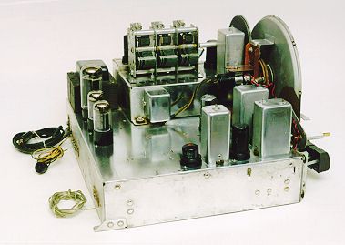
The magic tuning eye's placement is creative—right in the
center of the big dial pointer. The pointer's center is clear plastic,
allowing the tuning eye to shine through.
Main controls are located to either side of the dial. On the left
is the volume control. On the right is the dual-function
bandswitch and tuner control. The knobs for these controls were
missing when I took these photos. Since then, I have acquired a set of correct knobs from a fellow collector.
Thirteen pushbutton switches are arrayed below the dial. The
center button turns the power on. To the left are six tone controls,
three bass and three treble. To the right are six preset
buttons, which tune particular stations when the bandswitch is
turned to Auto. This radio was clearly sold in the Seattle area.
The presets are labeled with still-familiar
call signs, such as KING, KOMO, and KIRO.
Here's a list of the fourteen tubes and their functions.
| Tube |
Function |
| 6SG7 |
RF
Amplifier |
| 6AC7 |
FM mixer |
| 6SA7 |
AM
Converter |
| 7F8 |
FM oscillator |
| 6SG7 |
AM-FM First IF
Amplifier |
| 6SG7 |
AM-FM Second IF
Amplifier |
| 6SH7 |
FM Third IF
Amplifier |
| 6H6 |
FM
Discriminator |
| 6E5 |
Tuning
Eye |
| 6SQ7 |
AM Detector/
AVC/AF |
| 6AQ7 |
Phase
Inverter |
| 6V6GT |
Audio
Output |
| 6V6GT |
Audio
Output |
| 5U4G |
Rectifier
|
The sensitivity
and audio quality of this radio are quite good. The push-pull audio tubes also
provide lots of volume! The original schematic calls for
a 12-inch diameter speaker. I play it through a modern hi-fi speaker.
Restoration
As found, the radio had no identifying marks, other than the Crosley
name on the dial. Before I could order a schematic, I needed some clue
as to the model number.
I posted a question on the rec.antiques.radio+phono newsgroup,
and George Gonzalez quickly replied, "That sounds just like the radio I
restored for my brother-in-law. I think the model number is something like 146C."
Sure enough, the Slusser collector guide listed
a Crosley model 146CS whose description matched perfectly. I ordered a schematic
from Antique Electronic Supply without further delay.
As long as I had George's attention, I asked him to look on his schematic to help
me identify the two missing tubes. Comparing the full tube lineup to the tubes present
in my set, it appeared the missing tubes were both type 6SG7. I happened to have two
spares of that type, which allowed
me to give the radio a preliminary quot;smoke testquot; right away.
Before turning on the set, I cleaned the controls with De-Oxit
spray cleaner and did a quick inspection underneath. Nothing was obviously burned, but the speaker wires were badly
cracked and useless, so I soldered in replacements. Then I connected an antenna
and test speaker, and slowly powered up the radio on a variac.
To my delight, the radio worked! It sounded great on AM, less good on FM.
Satisfied that the set was not hopeless, I powered it down and gave it
a thorough cleaning inside and out. Then I embarked on the long
process of replacing capacitors.
Another initial step was to replace the 1-megohm resistor hidden in
the base of the 6E5 magic eye tube. That's a little trick you should remember
if you have a magic tuning eye. This resistor often changes
value, degrading the performance of the magic eye. If you didn't know
it was hidden inside the tube base, you might go nuts trying to diagnose
the problem!
In the process of replacing capacitors, I also checked voltages
according to the values given in the schematic, and replaced
several resistors whose values were out of spec.
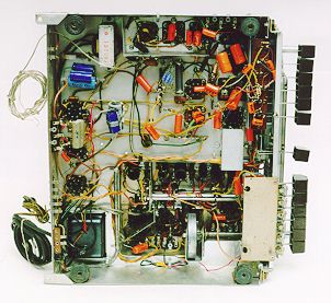
The chassis interior view shows
the radio around this stage. (Don't look too closely at that photo, by
the way! It was taken near the end of the restoration, when there still
a couple of temporary, jerry-rigged replacements in view. I cleaned
things up before declaring the job complete.)
Eventually, the radio performed well on all bands.
When the radio was removed from the cabinet, the previous owner had
snipped off the dual pilot lamps rather than leave them dangling. As
a final touch, I wired in new sockets and attached them to
convenient spots behind the dial with a dab of hot glue. The lamps
aren't needed for proper operation, but I hate to leave wires dangling.
Since the dial is opaque, and there are no attachment points on the
chassis, I assume the original lamps were mounted on the cabinet
and shone down on the dial.
Final Thoughts
I owned this radio for several years, playing it occasionally
in my workshop. Eventually, I sold it to a fellow who noticed
this article. He had an empty cabinet for this model, but
no chassis. Since my initial investment was small, I sold
it to him pretty cheap.
|