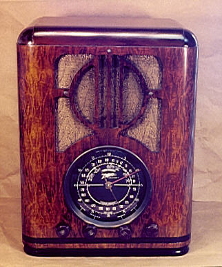
Zenith Model 6-J-230 Tombstone Radio (1938)


This classic "black dial" Zenith tombstone is a real jewel. The following photo shows the radio after I completed its restoration.
Model 6-J-230 dates from 1938 and is typical of many radios of that era. Using six tubes, it covers the standard broadcast band and shortwave frequencies from 5.6 to 18 megahertz.
The cabinet is simple but elegant, with a six-inch circular dial echoed by a circular design in the upper speaker grille. Zenith also used this cabinet for models 6-S-229 and 7-D-229 in 1938 and 6-S-330 and 5-X-230 in 1939.
The front and sides of the cabinet appears to be covered with finely grained veneer, but the "veneer" is actually a photographic decal of a wood pattern. This type of "photo-finish" can also be seen on my 1937 Philco 37-61 tombstone.
Contrasting with the black dial face is the gold-colored tuner pointer. It is made of polished brass with the famous lightning "Z" Zenith logo at its center. A second, red, "split second" pointer is used for logging shortwave stations. The split-second pointer moves more rapidly than the main tuner, making one circuit of the entire dial when the main pointer moves about half an inch. The dial perimeter is marked in gradations from 1 to 60, allowing you to record very fine tuning positions.
The controls are quite simple. The leftmost knob is a tone control and the next one in line is the power/volume control. Next is the tuning knob and the rightmost control is the bandswitch.
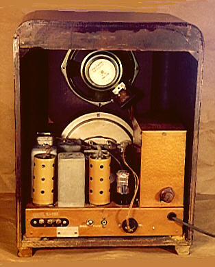
This radio can be powered from household AC current or a 6-volt DC battery. In the following rear view, look at the big box on the right side of the chassis.
The metal box atop the chassis has a switch on its back to select AC or DC operation. Inside the box are power-supply components, including the rectifier tube and (for battery operation) a vibrator.
Not shown in the photo are thick insulated battery cables. Since I operate the radio on AC, I shortened the cables and tucked them under the chassis. If I ever sell the radio, I'll replace the battery cables with new ones of the right length.
The chassis and round tube shields are painted with an attractive copper-colored hammertone finish. When I first got the radio, I thought that the chassis might be solid copper, which would be quite beautiful when polished. Polishing only cleaned up the paint, however. The underside of the chassis is plated with copper, however, perhaps to allow good ground connections for electronic components.
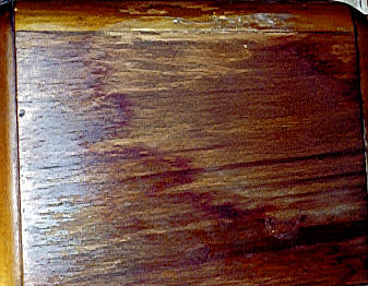
When I purchased the radio, it required total restoration. The photo-finished portion of the cabinet was in decent shape, but the top was badly damaged, as you can see below.

Part of the top finish was completely gone. Perhaps chemicals were spilled on it or someone made an aborted attempt to refinish it. Toward the front was a big messy splotch of some hard substance, possibly dried glue or some kind of varnish.
The radio's electronics were intact, but needed a complete overhaul. This is typical for a 1930s radio. Even if it plays, it undoubtedly needs some repair before you put it into regular service.
Cabinet Restoration
Fixing the cabinet was a straightforward job. Given the extent of damage on top, stripping was the only alternative. I used Citri-Strip, an easy to use, non-smelly gel stripper.
After stripping, I carefully buffed the top smooth with very fine #0000 steel wool. The next photo shows how the cabinet was masked with newspaper prior to applying the new finish.
Stripping made the top much lighter, so I sprayed on several coats of brown toning lacquer to match the dark brown of the cabinet body. After I had a good color match, I sprayed one coat of clear lacquer on the top, then removed the masking and the grille cloth to expose the whole cabinet.
The rest of the cabinet was in good shape, with only a few small scratches here and there. The black contrasting stripes near the bottom had a few scuffs, which I restored with black paint and a small artist's brush. To conceal blemishes on the photo-finished sides and front, I wiped on a coat of Min-Wax walnut stain with a soft cloth, let the stain set for a minute or two, then buffed it off again with a clean cloth.
When all the color work was done, I sprayed on two final coats of clear lacquer, lightly buffing the last coat with #0000 steel wool to achieve a satin finish that doesn't look "too new."
The original grille cloth was still in good condition. As with most old cloths, it had faded somewhat in the areas exposed to light, but not so much as to merit replacement. I used a very soft brush to brush out accumulated dust, then sprayed the cloth lightly with clear water and placed it face down on a sheet of cardboard to dry.
The light application of water shrunk the cloth slightly, getting rid of the sags. Then I applied a bit of liquid spray starch. The starch gives the cloth more body, helping it resist sagging in the future. After I reinstalled the cloth, the cosmetic restoration was complete!
Electronic Restoration
The 6-J-230 is a typical 1930s superheterodyne receiver, using a power transformer and six tubes. Here is the tube lineup.
|
Tube |
Function |
|
6D8 |
Converter/Oscillator |
|
6S7 |
I.F. Amplifier |
|
6T7 |
2nd Det./AVC/1st Audio |
|
6L5 |
2nd Audio |
|
1J6 |
Power |
|
6ZY5 |
Rectifier |
Restoring the electronics took a lot more time than touching up the cabinet. The first steps were standard: cleaning dust and grime from the chassis, spraying contact cleaner (DeOxit) inside all of the controls, cleaning and lubricating the tuning capacitor, removing and cleaning the dial glass, and cleaning the dial itself.
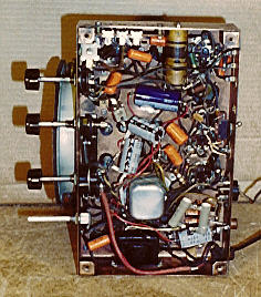
The next phase involved "recapping" the set, or replacing all paper capacitors and the filter capacitors in the power supply. The next photo shows the underside of the chassis after recapping.
The large gray and blue components near the center of the photo are the new filter capacitors. There was ample room to mount the new units underneath, so I did not attempt to conceal these inside the original capacitor cans on top of the chassis. Instead, I simply disconnected the old filters and left the cans in place to preserve the radio's original appearance.
The Tale of a Tuner
I also had to replace the drive belt in the tuning mechanism. The tuner on this radio is well engineered and quite interesting. On most old radios, a strong string drives the tuning capacitor. The string is wrapped two or three times around the shaft of the tuning knob and goes around a larger pulley attached to the tuning capacitor. Other small pulleys often act as guides for the string.
A string-driven system is cheap to manufacture and easy to service, but strings can break or slip. Slipping is an especial disadvantage for shortwave listening, where accurate tuning is all-important.
This radio uses a rubber drive belt instead of a string. The belt is made of layers of rubber-impregnated fabric, similar to the fan belt in your auto but much smaller. The belt runs inside machined brass pulleys and is held at the right tension by a spring-loaded arm. A gearing mechanism behind the dial transfers the belt's rotation to the tuning capacitor.
This tuning system is not only reliable, but also very accurate. Little force is needed to spin the large dial pointers and the tuning is quite precise. Providing accurate tuning via the main tuner obviates the need for a separate bandspread tuner, as found in "boatanchor" shortwave sets such as my Hallicrafters SX-42.
On my radio, the little rubber drive belt was shot. Its rubber had dried with age, allowing the fabric layers to separate and detach from one another. A few minutes of experimentation convinced me that strong cord would not be a suitable replacement. Only rubber would provide enough friction on the small pulleys to make the system work.
As it happens, Antique Electronic Supply sells an exact replacement belt for this particular model. When I got my hands on the new belt, however, I discovered a little problem. Putting on the new belt would require disassembling the geared tuning mechanism, starting with the dial pointer and dial, and working back to where the belt would be placed on the shaft.
The dial pointers were not easy to remove. The fragile pointers seemed to be held on by friction and they were on very tight. I didn't want to risk damaging the pointers during removal or getting them off safely but being unable to securely reattach them.
What's more, in the course of playing with the tuning mechanism, I discovered that the dial pointers are spring-loaded. You can feel the spring wind up if you move the tuner manually with the belt disconnected. The spring counterbalances the weight of the tuning capacitor as the plates rise up, allowing you to accurately rest the tuner at any position.
No spring is visible from the outside, so I assume it's concealed inside the large metal dial case. Perhaps this spring-loaded gizmo would have been easy to disassemble and reassemble, or perhaps it would have exploded in a shower of tiny parts all over my workshop floor, never to be put right. Before risking that, I decided to seek expert advice.
When I queried the rec.antiques.radio+phono newsgroup for ideas, I learned that many restorers don't bother buying "store-bought" replacement belts. Instead, they get rubber stock of the right diameter, cut it to the right length, wind the length around the pulleys, then super-glue the cut ends together. The preferred material seems to be rubber O-ring stock with a square, rather than round, cross-section.
After phoning a number of local stores, I was unable to locate square O-ring stock, so I bought the next-best thing: two rubber plumbing gaskets. The gaskets were about half the required length and twice the required thickness, but where there's a will, there's a way!
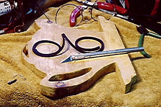
First, I cut the gaskets in half, making the cuts on the diagonal. Then I super-glued two of the cut ends together, forming a single length of rubber. The next step was to carefully split the rubber in half along its entire length. The next photo shows the rubber just before I finished splitting it.
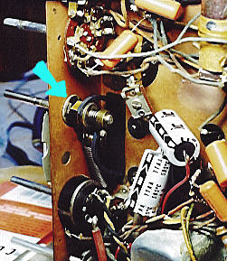
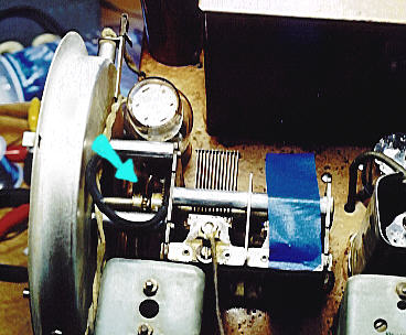
To attach the new belt, I needed to stretch it around the pulleys, trim one end to exactly the right length, then glue the ends together to make it back into a circle. Before doing this, I manually turned the tuning capacitor up, putting its spring under tension. The next photo shows how I taped the capacitor in place to keep the spring from pushing it back down. The blue arrow points to the shaft around which the belt is loosely placed.

The next photo shows the second pulley underneath the chassis. Again, the blue arrow points to the shaft and the belt is placed loosely around the pulley.
Once everything was in place, trimming the belt and gluing it was pretty easy. To my delight, the belt worked perfectly!
After finishing this repair, I received some additional email from newsgroup members, indicating that round-section O are easier to find
and they work just as well as square ones. In other words, I could have avoided the time spent laboriously splitting and regluing the square rubber material. In hindsight, another alternative would have been to cut and reglue the new belt that I bought from AES. Oh well, this is how we learn! On to the next challenge . . .
My Kingdom for a Lamp
At this point, the set played for the first time, but very poorly. The audio was extremely weak—barely audible with the volume control turned all the way up—until I replaced a burned-out dial lamp. (Thanks to Walt Heskes, an expert adviser on many of these projects, for pointing me in the right direction to solve this problem.)
On many radios, the pilot lamps are wired in parallel with the filaments of the radio's tubes. This scheme allows the radio to work if a lamp burns out. On this set, five of the six tube filaments are wired in parallel with the pilots, but the 1J6 power amplifier tube is wired in series with them. If either lamp burns out, the power tube gets no filament current, and you get almost no amplification.
Why would a radio designer do this? Take a look at the tube lineup. Five of the six tubes are 6-volt units, suitable for a radio designed to run on 6-volt DC power. The sixth tube, a 1J6, takes only one volt, however, as we can tell from the 1 at the beginning of its type number.
Under AC operation, the filament output from the power supply is 6.3 volts, fine for the six-volt tubes but too much for the 1J6. Each pilot lamp draws 2.9 volts. By putting the lamps in series with the 1J6 tube, the designer used the lamps themselves to provide dropping resistance. (For those who have noted that 2.9 + 2.9 + 1 equals more than 6.3, we should point out that there is also a small resistor in parallel with each lamp, to create exactly the right resistance.)
After I replaced the lamp, the radio played, but not very well. Despite new filter capacitors, there was still too much background hum. Substituting larger filters reduced the hum to an acceptable level.
More Capacitors, Please!
The audio was also harsh and extremely loud, so loud that the radio played at medium volume with the volume control turned all the way down. Testing further revealed that the tube voltages were very high, reading about 200 volts on plate pins that should have 125-135 volts.
In search of fresh answers, I opened up the large metal box containing the rectifier tube. In a small subchassis inside the box were several small components, including a handful of paper capacitors. I wasn't finished with the recapping, after all!
The next photo shows the power subchassis before replacing its capacitors. There was just enough slack in the connecting cables to let me replace those parts without unwiring all of the cables.
Incidentally, here is a case in which careful notes might have led me to these "hidden" capacitors sooner. Had I checked off each capacitor on the schematic and parts list as I worked, I would readily have seen that the job wasn't complete. Since doing this restoration, I have gotten in the practice of writing down every replacement as well as the results of every test. Note-taking may seem tedious when you're hurrying to get results, but it saves time in the long run.
Too Hot for Comfort
After those capacitors had been replaced, the radio's B+ voltage was lowered somewhat, but it still tested about 25-30% higher than indicated in the schematic. Acting on further advice from Walt Heskes, I added a bleeder resistor to bring the voltage down. The following email snippet continues the tale:
From: Phil Nelson
To: Walt Heskes

Bingo! Putting a bleeder resistor between the plus side of C19 and ground
did the trick. Tried a 1W resistor first, but it quickly overheated, so I
hauled out my old bag full of salvaged 5W units. These are big fat
ceramic-coated resistors with lugs on each end. After some experimentation,
I found that two 2.2K resistors in series reduced the voltage to 135vdc,
where the spec calls for 137. Right on the mark, in other words.

The bleeder gets pretty hot, so I mounted it as far as possible from the new
rubber drive belt in the tuner mechanism.

The new resistor also introduced more background hum, so after trying
various cap values in parallel with C19, I ended up with an additional
100mfd cap in the filter. Now C19 is 147mfd (!), but we have no trace of
hum.
Fixing the voltage problem introduced a new glitch, however, as the following email explains.
From: Phil Nelson
To: Walt Heskes

Well, the power supply mods seemed to work fine, so I proceeded to the
realignment. Went through the full-dress alignment parade *three* times.
Once should be enough, but we didn't seem to be making any progress.
Followed the book religiously, I swear. The result: loud chirpies on BC,
horrible audio everywhere, complete mud on SW.

What's going on here? Turn the set over again to double-check for bad
connections. Nothing looks messed up, but Oh -- maybe we could try tweaking
these two little trimmer caps underneath the chassis which aren't mentioned
in the alignment instructions, just to see what happens. Before we do so,
let's turn the set back on and let it warm up. In the meantime, tune to a
local BC station to alleviate boredom. And let's nudge that newly installed
bleeder resistor over to one side to make sure that the probe won't short
out against its lugs.

Whoa! Touching, nudging, breathing, doing *anything* to that resistor makes
a huge difference. Oh, wait a sec -- that thing's mounted right between the
coils. Maybe there's a reason why the designers put the power supply on one
side of the chassis and the antenna & oscillator on the other side.

Let's see if that resistor's at fault. Power down. Disconnect bleeder.
Disconnect extra filter cap to make room for bleeder on opposite side of
chassis. Move bleeder to opposite side. Move filter cap to the other side.
Cross fingers. Say twelve Hail Marys. Power on.

Praise be to the powers, whoever they may be! This thing finally sounds like
a radio, on BC and SW, and the audio is considerably better than before.
One more alignment tomorrow . . . .
With the addition of a bleeder resistor—properly positioned to avoid interference—the radio performed quite well.
Why would the B+ voltage be too high in the first place? Here is Walter's comment on that point:
From: Walt Heskes
To: Phil Nelson
...
There are any number of reasons for this anomaly. They include
higher line voltages, fresh electrolytic caps with higher voltage
ratings than the original parts, and a mix of old and new resistors
and coils that, together, change the voltage potentials throughout
the circuit. The source really makes no difference as long as you
are able to put some control back into the circuit.
Now that we have added an extra resistor, can this radio be considered "stock" or "original?" Well, why not? Sure, it has one extra resistor not specified in the schematic. On the other hand, the radio didn't perform to its original specifications until we added that part. So in terms of performance, it is "original," possibly even working closer to the designer's specs than when it left the factory. If you feel uneasy about modifying an old radio, you can always leave a note inside the cabinet indicating exactly what was done, so that any future owner who doesn't like the modification can undo it.
Aligning the Receiver
Alignment is a routine restoration procedure, although I have often skipped it when the radio performed well after recapping. If you haven't replaced certain critical components, and nobody has messed things up in the past, the alignment will be fine in many cases.
In this case, however, the radio's performance was quite poor, as mentioned earlier. Not only were there problems with signal weakness, but at one point it gave out "birdy" squeals while tuning, a symptom often due to misalignment. Even after solving those gross problems via the power supply fix, the dial tracking was not very accurate. (That is, the dial pointer did not always point exactly to the station being tuned.) A final alignment was in order, particularly since I had already changed the alignment earlier.
Caution: A novice should never try to align a radio "by ear." Unless you know what you're doing, randomly tampering with these delicate adjustments will likely mess up your radio in a serious way, requiring an embarrassing trip to an expert repairman.
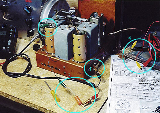
The minimum equipment needed for alignment is a signal generator and a multitester. You will also need the alignment instructions from the schematic, of course. The next photo shows this radio on my workbench with everything set up to align it.

Numbers in the photo identify various components:
- Autotransformer (variac), used to supply a precise voltage to the radio. Not really necessary for alignment, but I power all of my radios on the workbench through the variac, which in turn is powered through an isolation transformer for safety.
-
Digital receiver, used to double-check the signal generator's output frequency.
-
Signal generator, used to create a test signal at a precise frequency.
-
The radio being aligned.
-
A multitester, used to measure the radio's output during alignment. Connected in parallel with the radio's speaker leads.
-
The radio's speaker.
This radio requires eleven separate alignment adjustments. The next photo shows the setup for the first adjustment. Numbers in colored circles identify points of interest.
Numbers 1 and 2 in the photo identify the connections between the signal generator and the radio. Number 1 shows the ground terminal of the generator connected to the ground terminal on the radio's antenna strip. Number 2 shows the signal ("hot") lead of the generator connected to the grid lead of the 6D8 tube.
As Number 3 shows, the signal generator's hot lead is not connected directly to the radio. Instead, a .5-mfd capacitor is connected in series between the two devices.
Number 4 shows the multitester's probes clipped to test leads in parallel with the radio's speaker terminals. This allows you to precisely measure the final output on the multitester. For most adjustments, you simply turn the screw while watching the tester's readout, aiming for maximum output.
Before making the adjustments, I used a digital radio to double-check the signal generator's setting. This isn't absolutely necessary if you have a good signal generator, but my generator is as old as many of the radios that I own and its dial is not very accurate.
Checking a generator's output in this way is another of Walt's handy tricks. To do it, you first fashion a simple coil of wire, about three loops and roughly six inches across. If you look closely at the workbench photo, you'll see the thin red loop lying under the digital radio. Connect the signal generator's leads to the ends of this loop and place it near the digital receiver. Then tune the digital radio to the desired frequency and start fine-tuning the signal generator to the target frequency. (If your radio can't tune to the target frequency, tune it to a multiple. For instance, my radio doesn't tune to 456 kilohertz, but it does tune to 912, double the target frequency.) You will hear a loud hum in the radio when the generator is set just right. Then you turn off the digital radio, disconnect the generator's leads, and reconnect them to the radio being aligned.
For this particular adjustment, the signal generator was set to 456 kilohertz to adjust the radio's I.F. (intermediate frequency) coils. Different connections and test frequencies are used for subsequent alignment steps, of course. By the time I was done, the radio was playing beautifully and its dial tracking was right on the money. After reinstalling the radio in its cabinet one last time, the restoration was complete!
Final Thoughts
In hindsight, I'd call this restoration moderately difficult. Although there was nothing unusually hard or time-consuming about the cosmetic work, the electronics took more time than I had expected. Cleaning and recapping are standard practice, but solving the voltage problems added extra hours. In the process, however, I learned more about this type of radio and added a few new items to my bag of repairman's tricks.
This handsome set has earned a number of compliments from visitors. Other tombstones in my collection include the 1937 Philco 37-61, 1934 GE S-22X, and 1938 Stewart-Warner 91-531.
|