Hallicrafters Model SX-42 Communications Receiver (1947)


 Owner's Manual
The Big Kahuna! Widowmaker! If you have ever tried to lift a
radio this size, you know what I'm talking about. This superlative
communications receiver represents a peak of post-World War II
radio technology. And it weighs about as much as
a 1947 Buick.
Description
Model SX-42 was the top-of-the-line Hallicrafters radio of its
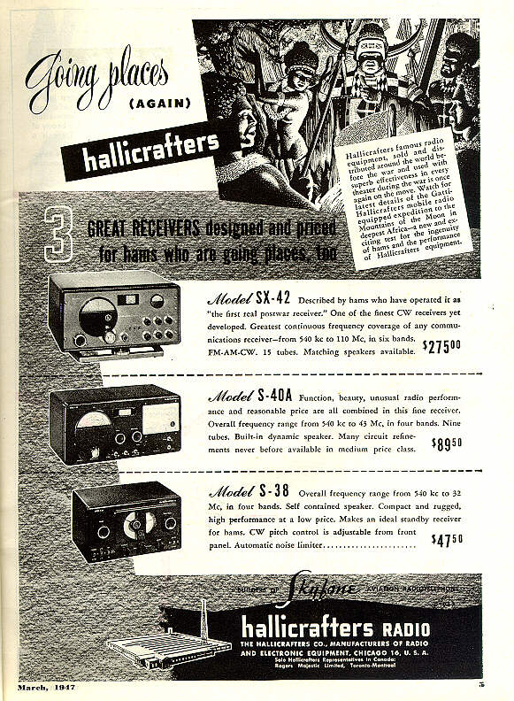
time, and the company promoted it accordingly. The
March, 1947 front cover of Radio News magazine showed an SX-42
as it would have been used in the Gatti Expedition to South
Africa. The SX-42 was also featured in full-page ads in the
April, 1947 and December, 1946 issues of Radio News. (Click the thumbnails below to view the full-size
magazine pages; you can view many more magazine images in our
Literature section.)


I think the magazine cover is a real hoot. Intended to look
authentic, it seems awfully stagy to me, with a fez-hatted
native peering curiously through the window at an earnest young radio operator.
And the magazine's scene dresser couldn't resist a little bit of self-promotion.
If you look closely at the magazine cover, you'll see the
December, 1946 issue of Radio News
on the desk under the young ham's left arm.
As the Hallicrafters ad indicates, the SX-42 sold for $275, a princely sum
in those days. Its features also appealed to the most demanding
radio listeners. Using 15 tubes, this radio covered the AM
frequencies in six bands from 540 Khz, the
bottom of the standard AM broadcast band, to 110 Mhz. It also
offered FM reception in the two highest bands: 27-55 Mhz
and 55-110 Mhz.
Hallicrafters touted the SX-42's wide coverage, stating
it had the "greatest continuous frequency coverage of any
communications receiver." That was doubly true of its FM
coverage. Prior to World War II, FM radio
broadcasts were found in the 42-50 Mhz range. After the war, FM
broadcasts were shifted upward, to today's 88-108 Mhz range.
By designing the SX-42 to receive FM in the radio's two highest
bands (27-110 Mhz), Hallicrafters covered both of those standard
ranges, and then some! You can read more about the
change in FM frequencies in my page on the Philco
42-350.
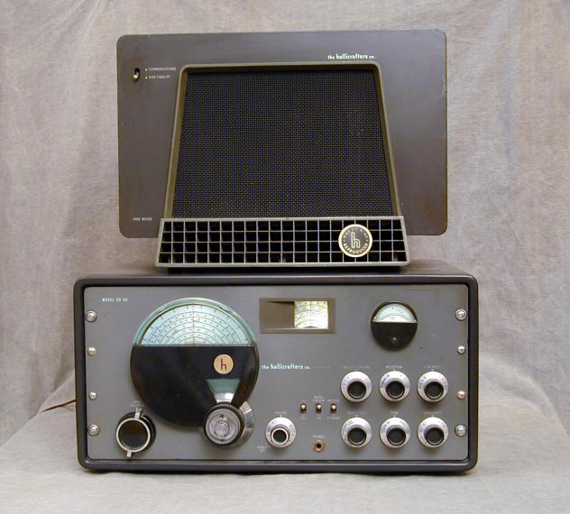
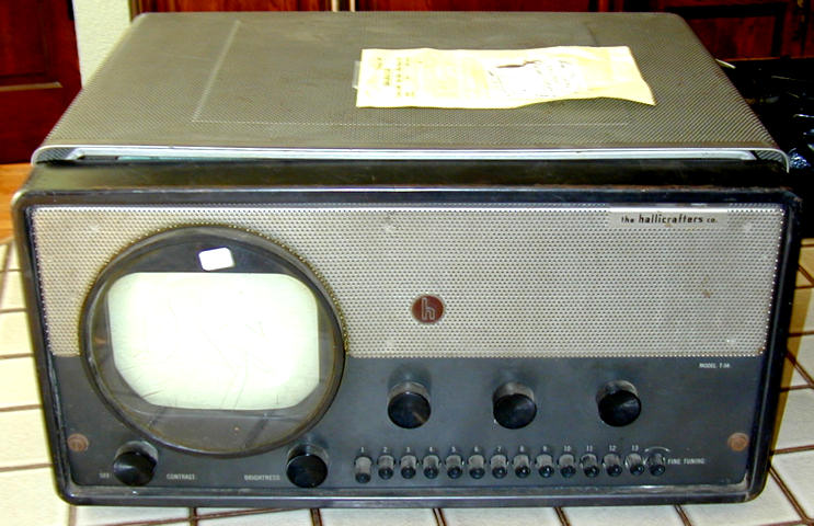
The next three photos show the SX-42 along with an interesting companion set,
the model T-54 television. The first photo is from Hallicrafters literature.
The second shows my SX-42 and the third shows my unrestored T-54.
The design for the SX-42 and T-54 is credited to the famous Machine Age
designer, Raymond Loewy. You can read more about early Hallicrafters televisions
in my articles about the T-54
and model 505.
Hallicrafters offered a matching speaker for the SX-42, the model R-42 "reproducer,"
as well as an optional tilt-swivel base. The swivel base
is extremely rare. The photo above shows the radio with my R-42 on
top. Although it looks nice for a photo, I don't recommend keeping the speaker on
top of the cabinet permanently. It's heavy and it might interfere with ventilation.
In the Radio News magazine cover shown above, you can see an earlier-model
speaker (PM-23) to the right of the young ham's SX-42. The PM-23 speaker
is electronically compatible with the SX-42 but it was designed to
match earlier receivers such as the SX-28.
This complex receiver has a lot of controls. Rather than paraphrase
the original source, I have provided a separate page with the
complete Detailed and Technical Operating
Instructions from the SX-42 Owner's Manual.
Here is the lineup of the receiver's fifteen tubes:
| Tube |
Type |
Function |
| V1 |
6AG5 |
1st RF amplifier |
| V2 |
6AG5 |
2nd RF amplifier |
| V3 |
7F8 |
Converter |
| V4 |
6SK7 |
1st IF amplifier |
| V5 |
6SG7 |
2nd IF amplifier |
| V6 |
6H6 |
AM detector/Noise limiter |
| V7 |
7H7 |
1st limiter |
| V8 |
7H7 |
2nd limiter |
| V9 |
6H6 |
Discriminator |
| V10 |
7A4 |
BFO/S meter amp |
| V11 |
6SL7GT |
Audio inverter |
| V12 |
6V6GT |
Power output |
| V13 |
6V6GT |
Power output |
| V14 |
5U4G |
Rectifier |
| V15 |
0D3/VR150 |
Voltage regulator |
The rear view shown below gives a peek into the SX-42's interior.
This shot is taken from the rear. At lower left is the large power
transformer, a black rectangular object with the Hallicrafters "h"
logo molded in the top of the case.
To the right are the huge tuning capacitors. The main tuner
lies to the right in this view, and the bandspread tuner to the left.
This section is normally covered from above by a large rectangular metal
shielding plate. I removed the plate for this photo, but you can
see three of its mounting posts in this view. If you shop for an
SX-42, pay attention to whether this plate is present. It's an easy
thing to lose, and the designers put it there for a reason.
The SX-42 is especially attractive to me because I like to listen
to FM and shortwave late at night, and I appreciate good
audio quality. It's hard to find any vintage tube radio—much less a
boatanchor—that offers all those features in one package.
(One exception is the luxurious Scott 800B6.)
If you go shopping for an SX-42, don't confuse it with a
model SX-43. The two radios date from around the same time,
and look very similar, but the SX-43 is a cheaper 11-tube model,
selling for $105 less than the SX-42. The simplest way to tell them apart
is to look at the main tuning dial on the left front. The SX-43's dial is plain
on the bottom and has the Hallicrafters "h" logo on its left side.
The SX-42's main dial, as you can see in the front view,
has the Hallicrafters logo on its right side, and the distinctive
bandspread dial is "notched" into the main dial's lower right edge.
Like its bigger brother, the SX-43 covers FM bands, both the prewar
42-50 Mhz band and the modern 88-108 Mhz band. I don't mean to imply
that the SX-43 is not a good radio. Just make sure you understand
which radio you're looking at. All things being equal, an SX-42 would
be worth more than an SX-43.
A few other Hallicrafters sets combine FM with shortwave.
Model SX-62, made from 1949-1953, is a somewhat more
consumer-oriented version of the SX-42, lacking a few
"boatanchor" features such as bandspread.
Model S-47, introduced in 1947, is a 15-tube AM/FM/SW
chassis designed for consumer use, offered in various
console cabinets or sold as a bare chassis for installation
in a custom cabinet. These seem to be quite rare.
Much later, in 1966-1967, Hallicrafters
sold a few cheaper tabletop radios—some solid-state—that
covered the standard FM broadcast band as well as some
shortwave bands. The SX-42 stands alone, however, in offering
continuous coverage over a very wide range, as well as high-end audio.
First Look
As found, this radio worked—sort of. It sounded fine
on the standard broadcast band, but had a serious shorting
problem when you moved the bandswitch to FM. (The seller
had warned me of this condition, so it didn't come as
a surprise.)
Cosmetically, the set was not perfect. The front panel was
starting to develop some light surface rust, but it looked
quite presentable after cleaning, and the lettering was in good shape for
a 52-year old radio.
The hinged top cover dips slightly in the middle, causing
its front edges to stick out very slightly to the side when closed. That's
a common problem in sets with hinged covers, probably caused when someone
parked another heavy piece of equipment on the cover.
I suspect that I can straighten the cover by carefully clamping it
sideways in a long woodworking clamp.
The first thing I did after receiving the radio was to
remove it from the chassis, brush off the surface dirt,
and clean all the controls with DeOxit. I also examined
all the interior wiring for obvious loose connections,
wiring breaks, or solder bridges.
Then, with the bandswitch
set to the BC band, I hooked it up
to my variac and slowly powered it up
under increasing voltage.
That procedure lets you watch for problems
during a gradual "smoke test."
On BC, the radio performed pretty well, as the seller had claimed.
The shorting problem on FM was still there, however.
Powering down, I decided it was time for closer
examination.
There are two controls that might be at fault here: the
complex bandswitch, which chooses a particular frequency range,
and the much simpler Reception control, which chooses different
reception modes: CW (code), AM, FM, or Phono. Using a
ohmmeter and following the schematic, I quickly
determined that there was nothing wrong with the Reception
control.
That left the bandswitch, which is not like any switch I had
seen before. This is not something that you can remove in one piece
and rebuild on the bench. It's an eleven-gang switch assembly
running the entire length of the radio,
around which many other components are wired, in a sort of
dense electronic forest.
Simply finding the problem would be quite a challenge. Fixing
it might be even harder.
Time to call on a higher power! Reloading my checkbook,
I hauled the boatanchor to a local repair shop, the
same one that had fixed up my Hallicrafters SX-122.
When I brought the set in, the proprietor grumbled, but
said he would look into the problem, giving no guarantees.
"I might have to charge you more than the radio is worth,"
he warned.
When I phoned for an update one week later, the news was not good.
"Come to pick it up and we'll talk then," he said. When I arrived at
his shop, the radio was playing wonderfully on AM. Then
he delivered the bad news. "There's a part of the switch
that's completely burned away. You don't want me to tear apart
that whole end of the radio," he said. "I haven't got time
for that anyway. I bridged the burned section of the
bandswitch so that it can play on AM. I won't charge you for all the
time I spent—just pay me $25 and we'll call it square.
It's a nice radio, but if I were you, I'd try to swap
for one that works."
A Tale of Two Switches
Handing over the $25, I sadly hauled my SX-42 home, vowing that
this would not be the end of the story. Against hope, I posted
a message in the rec.antiques.radio+phono newsgroup, asking for
advice, or at least condolences. Then I packed the radio onto
a shelf in the garage.
A couple of weeks later, I got an email message from a guy
in California who had a mostly-stripped SX-42 chassis
with an intact bandswitch. If I paid the shipping cost, he said,
he'd be willing to box it up and send it to me gratis.
Yes, I replied! One week later, for a cost of about $12, I had
a second SX-42 chassis with a good switch. By that time, my family
was in the process of moving to a new house—not a good time to
have a boatanchor in pieces on the workbench—so I shelved both
units for the time being.
Months later, we were finally
settled in our new house, and I found some time
to work on this project.
The first step was to replace the old paper capacitors. This set has a lot of
capacitors. I stopped counting after a while, but I believe
I replaced about three dozen of them.
I call the next photo "Beauty and the Beast." It shows
the newly recapped SX-42 on the left, and the junker
chassis on the right.
In this view, the bandswitch is at the top of both chassis.
The long rod running the length of the chassis is one of the
side supporting shafts for this very large switch.
The repair guy told me that one wafer of the switch was
burned beyond repair, so I assumed I would have to
replace that wafer. To find out how hard this would be,
I started to disassemble the switch on the junker chassis.
The next photo shows one of two wafers which I removed
from the junker chassis.
Although the wafer is electronically identical in both chassis,
the newer wafer differs in some construction details. Notably,
where the wafers in my older SX-42 use round rivets to secure
central rotors through to the other side of the wafer, this newer
design uses split crimps.
The switch is built around a center shaft and two side shafts.
The center shaft turns the center rotors, and the side shafts
secure the stationary, outer portion of each wafer.
The side shafts are simply long brass screws running
through all eleven switch wafers.
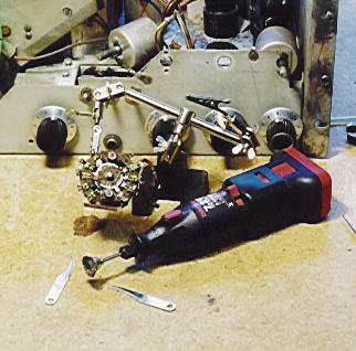
To replace any of the wafers, you need to pull out
all three shafts. The following photo shows the shafts from the
junker's bandswitch.
Also visible in the photo are a rectangular side plate, which
is removable for aligning the radio, and a dish containing
all of the nuts and little pieces of metal collar which
fall loose when you withdraw the side shafts.
On newer SX-42 models, such as my junker, the center shaft
is made of two pieces, which you can disassemble by
loosening two screws near the detent gizmo. This allows
you to pull the center shaft out through an access hole
in the rear of the chassis. The side shafts are also
held with nuts on both ends, and can be drawn out through
access holes in the front of the chassis.
On older SX-42s, such as my "good" one, the side shafts
and center shaft are riveted on to the detent gizmo at the knob end.
To remove any wafer, I would have to drill out the rivets before
removing the shafts. When I
reassembled the switch, I would substitute the side shafts
and two-piece center shaft from the newer radio, as well
as the newer detent gizmo.
You can understand why Hallicrafters made this design improvement.
The older switch design makes it very hard to replace a wafer!
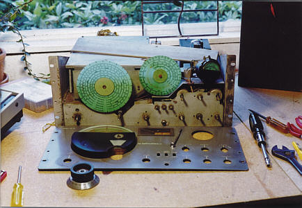
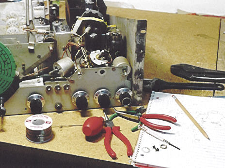
To gain better access to the switch, I removed the entire
side panel from the radio. I also bought an extension light
with a large magnifying lens, to get a better view into
this dizzying switch. The following photo shows the radio
with side plate removed and the magnifier giving a closeup
view.
Removing the Front Panel
Assuming that I would eventually have to remove the shafts,
I removed the radio's front panel to access to their front ends.
The next two photos illustrate
this process. First, you need to remove all of the knobs.
The smaller knobs are secured with small Phillips-head
screws, two setscrews per knob.
The bandswitch knob and tuner knob are secured with 5/64-inch
hex setscrews. Located at the end of deep, narrow holes, these
setscrews are hard to see. I used a flashlight and a bright
extension light to spot them.
The tuner knob has three parts: the main tuner, the
bandspread tuner, and the small winged lock in the center
recess of the bandspread knob. (The lock lets you clamp
the main tuner while using the bandspread, and vice versa.)
You can remove the locking piece by
simply unscrewing it counterclockwise. This exposes a tiny locking collar
at the shaft of the bandspread knob; the collar can
be removed by carefully prying it loose with a
small screwdriver or needle-nose pliers. This collar is
very small and it has a tendency to spring free when
released. Don't lose it!
To remove the bandspread knob, you need to rotate the
main tuner so that an access hole in the tuner knob
lines up with each of the two setscrews in the shaft
of the bandspread knob. This is where a flashlight
helps a lot! To aid in refastening this one, I scribed
two tiny lines in the center part, pointing
to where the setscrews should go.
The previous photo shows the SX-42 with all knobs removed
except the main tuner. This knob is also secured with two
hex screws on its shaft, but since part of the knob lies
behind the dial cover, it can't be pulled completely free until
you loosen the front panel.
Once the knobs are all free, you can remove the four large
screws from the sides of the panel and the securing nut
for the headphone jack. The last step is to remove
the radio's S-meter (at upper right in the previous photo).
The S-meter is secured with a thin locking collar behind
the front panel. After removing the collar, you also need to
remove three small screws around the edge of the meter case.
This lets you slip the case out through the front of the panel
while you slide the meter itself back from the rear.
Now you can take off the front panel, gaining
access to a number of otherwise unreachable components.
Before going any further, I reassembled the S-meter to
prevent damage. The meter is completely unsupported when
the panel is off, so I used a plastic tie to temporarily hold
it to the chassis side panel. The next photo shows the
radio with its front panel removed.
Although the radio loooks quite naked in this state, it can
still be operated as usual. To allow testing during repair,
I reattached all the knobs and set the radio on its side.
I also hooked up an antenna and speaker.
Happy Birthday, SX-42!
On the back of the front panel, I found a date stamp
that looks like May 6, 1947. The next photo shows
a closeup.
Strictly speaking, I suppose this date tells you when the
front panel was made, not necessarily when this particular
radio left the assembly line. But in the absence of any other
evidence, I'm using it as this radio's birthday.
I've been told there are at least two variations of the
SX-42, with differences in the front end and AVC circuits.
Mine is clearly an earlier model, with serial number
HA-77712. The junker is a later model, with serial number
HA-93256. In addition to the bandswitch changes, several
other small differences are visible in what's left of my junker.
Help Through the Ether
At this stage, I had invested considerable effort without
getting any closer to my goal, although I had learned plenty
about how to bare an SX-42 chassis for repairs. While I had
the front panel off, I thought I might look into repainting
it. I posted a question to the rec.radio.amateur.boatanchors newsgroup,
asking if anyone knew a way to repaint the front panel
including the lettering. Fellow SX-42 owner A.B Bonds sent this reply:
-------------------------------------------
From: A. B. Bonds
To: Phil Nelson
Date: Tuesday, October 06, 1998 7:15 AM
Subject: Re: repainting boatanchor front panel WITH lettering?

There is no practical way to repaint the lettering on the SX-42 panel.
It's multicolor, silkscreened.  To reproduce it would cost several hundred
bucks.  If you can get paint that is a close match, you can feather the new
paint around the existing lettering.  One of my SX-42's has had that done
(dunno who did it) and it looks mighty fine.  I did this with an S-76.  It
involved masking out the old lettering (to make sure), cleaning the old
surface with a mild solvent, then applying the paint with an airbrush,
staying reasonably far away from the masked areas so as not to make a line.
 After letting it dry for several days, I rubbed the new paint out to
de-emphasize the boundary with the old paint, then polished with a swirl
remover.  Car polishes are ideal for this.

Couldn't help notice your reference to "the cussed bandswitch".  I posted
about four notices on my experiences with this critter on the boatanchors
mailing list.  The third wafer from the rear carries both B+ for the first
RF tube and grid signal.  When bypass caps fail, the B+ current goes up,
heating the switch contacts.  On mine this had carbonized the wafer.  Even
the slightest amount of conductivity biases the grid positive. I ended up
fixing it in place, but it was a trial.  Basically scraped out all the
black with a dental tool, then refilled with epoxy.  Took about three
evenings.  A truly cussed design.  Did you actually remove your bandswitch?
Sheesh.

73 A. B. Bonds
-------------------------------------------
Finding anyone who had wrestled with an SX-42 bandswitch seemed
like a godsend. Over the next few days, I got even more
good advice from Mr. Bonds. The email exchange speaks
for itself.
-------------------------------------------
From: "Phil Nelson"
To: "A. B. Bonds"
Date: Tue, 6 Oct 1998 09:23:16 -0700

Hi, thanks for the useful information. You're the first person
giving advice who has actually worked on an SX-42 !

The panel on mine isn't in horrible shape, but it's not
great, either. If I had not already put so much time into the
set, I'd probably polish it up and leave it alone. Your
technique would work, I guess. Can I ask what sort of
paint you used, and how you went about matching the
color?

Regarding the switch, this has been a long, long trial
for me. The fellow who sold me the set said it had some
sparking problem in the bandswitch, but I had no idea
at the time just how beastly complicated and crowded
that switch is. I certainly wouldn't have bought it, had I
known.

When I bought the set, it played OK on BC, but shorted
when moved to other bands. After getting a look at the
switch, I hauled it to a local repair guy who had done some
work on an SX-122 for me. He spent some time on it and
decided not to tackle that switch. According to him, there
is at least one contact burnt completely away, so you
would have to replace the whole wafer. He said it would
cost me more than the radio is worth, just to get the
switch working. Plus, he really didn't want to do the job. So
I brought it back home again.

He hot-wired the set so that I could play it on BC, at least.
This was done by wiring a jumper wire between two little
terminal blocks mounted near the back, one underneath
each 6AG5 RF tube. I haven't traced it exactly, but it
looks like the jumper connects to about pin 6 of each
6AG5 through a resistor.

Meanwhile, I have completely recapped the set. I think
there were almost 35 paper or plastic capacitors! It now
sounds very, very good on BC. No trace of hum, so I haven't
messed with the filter caps.

Last year, I got a junker SX-42 chassis that has a good
bandswitch. Yesterday I partially disassembled that switch to see
just how awful the job would be. The answer seems to be,
PRETTY AWFUL. I'd be worried about wrecking the coils
crammed in there, for one thing. And I'm not sure how
I'd get a snipper back in there to disconnect some components,
short of starting at one end and tearing out every wafer until
I got to the bad one.

In the course of recapping, I also noticed that someone (maybe
my repair guy) had snipped a couple of connections at
the tone control switch. After I restored them, the radio
plays fine with the tone set to Hi-Fi or Bass. It shorts out
when switched to Low or Med, which seems very weird to me.

Needless to say, I would appreciate any advice you could
offer. The set is sitting on my workbench right now, with
front panel and side panel removed, ready for me to tear
into that switch. If you can remember exactly which part(s)
of which wafer was bad on your set, maybe that would help
me know where to start. I know its original shorting problem
was in one of the rear wafers, but now I'm having a hard time
seeing anything down in there. And the original shorting
problem seems to have gone away! Maybe because I
replaced the bad cap(s) that caused it in the first place.

Cheers.

Phil Nelson
-------------------------------------------
From: "A. B. Bonds"

At 09:23 AM 10/6/98 -0700, you wrote:
>Hi, thanks for the useful information. You're the first person
>giving advice who has actually worked on an SX-42 !

Been there, done that.  I am greatly sympathetic.  First, don't give up
hope.  Once fixed, it's a very hot (sensitive) radio that sounds _great_
what with the push-pull output stage.
FM performance is quite nice, and it deserves a good speaker.  I have mine
playing through a Rat Shack small Linaeum speaker (which is currently on
clearance sale) and it sounds mighty fine.

>Can I ask what sort of paint you used, and how you went about
>matching the color?

I didn't do my SX-42, I did an S-76 that uses a satin black, used Rustoleum
satin black.  There is a guy (I think the outfit is RR designs) who sells
custom-blended paints for boatanchor rx's.  I'll try to find his net
address.  It's a good bet to try an auto paint supplier, they have machines
that look at the color and give a recipe for blending the color.  Be aware
that the finish is not a gloss, it's kind of a flat grey.


>I certainly wouldn't have bought it, had I known.

Sounds familiar.  But now you are owner of the problem, and it's important
to try to do your best to fix it.

>When I bought the set, it played OK on BC, but shorted
>when moved to other bands.

That's because the first two bands (BC and the next one) do not use the
first RF stage, it only kicks in on band 3 and above.

>After getting a look at the
>switch, I hauled it to a local repair guy who had done some
>work on an SX-122 for me. He spent some time on it and
>decided not to tackle that switch. According to him, there
>is at least one contact burnt completely away, so you
>would have to replace the whole wafer.

Probably an accurate diagnosis.  Note however that if a contact is burnt
away, it is possible to replace that contact without necessarily removing
the bandswitch.

The wafer that usually is problematic is (I believe) third from the rear
end.  To access it, you need to remove the wide shield nearest the rear
(there is a smaller one behind it, but this does not need to be moved).
This involves desoldering the big copper strap connecting the shield to the
rear of the chassis and desoldering the components on the circuit strip
attached to the shield, as well as one capacito ground near the copper
strap.  In addition, to get at one of the screws holding the shield down
(nearest the edge) you have to remove the screen circuit components from
the single terminal phenolic strip.  This is accessible through the
(removed) side cover.  You also need to remove the entire side plate, since
the shield is attached to it with a braid.  This will give you pretty good
access.

I used a magnifying loupe to examine the switch closely.  The damage on my
switch was limited to burnt phenolic, both on the outer rim of the switch
as well as the rotating part.  I used a dental excavator (little tool with
a very tiny sharp scoop on the end) to scrape out the carbonized area in
the outer wafer and the rotor.  You have to be very careful here.  Even
when your meter reads 20 meg + resistance, when you slap 250 v on the
wafer, microamps can leak over and improperly bias your first RF tube.  One
way of telling if your repair is satisfactory is to look at the screen
voltage (with screen circuit clipped together).  For the first RF tube, it
should be about 150 v with the sensitivity turned up and no signal (only
measurable on bands 3 and above).  If this voltage is low, you have grid
leakage.  If you can sneak a probe into the grid pin, it should read very
close to 0 v.  Even + 1 v on that RF tube will cause problems.  Once the
offending carbon has been removed, I locally strengthened the switch by
standing the radio on end (nose down) and spreading on some partially set 5
min epoxy (so it won't run).  After about ten minutes for setting work the
switch to make sure it is loose and to permit removal of excess.

If you really have a burnt (outer) contact (the little springy thing), you
can use a Dremel tool to grind off the attaching rivet, remove the
individual contact and mount a replacement off your junker switch with a
short 2-56 screw and nut to hold it in place.  If your rotor contact is
burned as well, I am at a loss.....

>He hot-wired the set so that I could play it on BC, at least.
>This was done by wiring a jumper wire between two little
>terminal blocks mounted near the back, one underneath
>each 6AG5 RF tube. I haven't traced it exactly, but it
>looks like the jumper connects to about pin 6 of each
>6AG5 through a resistor.

Dunno what that means.  Pin 6 is the screen, which is activated all the
time.  The bandswitch passes both the grid and the plate voltage.  And you
don't use tube #1 for BC listening....

>Meanwhile, I have completely recapped the set. I think
>there were almost 35 paper or plastic capacitors! It now
>sounds very, very good on BC. No trace of hum, so I haven't
>messed with the filter caps.

Your count is about right.  Yup, a GREAT sounding set.  Coupla pointers:
(1)  On two sets I have worked on, the noise blanker switch had gotten
corroded so that it did not close properly.  This set the blanker ON
all the time, which distorted the stronger stations.

Check to see if this switch is closed when set to "off".  If not, you can
fixt it (with the front panel off) by removing the shield over the switches
(have to take off the bandspread dial).  You will see two tiny squarish
holes through the phenolic near the switch terminals.  Spritz some De-Oxit
through these holes and work the switch.  (2)  I found that most of the
resistors were OK, but the 220k resistors in the audio section were very
high, and most of the 1w and 2w power resistors needed to be replaced.

>Yesterday I partially disassembled that switch to see
>just how awful the job would be. The answer seems to be,
>PRETTY AWFUL.

I agree, this is an absolute BEAR.  Try the local fix I describe above.  I
couldn't even figure out how to get the switch shaft out (to replace a
single wafer) without totally disassembling it.

>I also noticed that someone (maybe
>my repair guy) had snipped a couple of connections at
>the tone control switch. After I restored them, the radio
>plays fine with the tone set to Hi-Fi or Bass. It shorts out
>when switched to Low or Med, which seems very weird to me.

That switch has been known to burn contacts as well (sigh).  Usually this
is a result of leaky caps, so if your caps have been replaced you should be
in good shape.  You need to make sure that the wiring follows the
schematic.  BE AWARE that there are at least two versions of this radio,
"early" and "late".  I don't know where the cutoff is in terms of serial
number.  There are at least three differences between the versions, in the
front end (RF), the AVC circuit and detector.  The usual
Hallicrafters/Ryder schematic is of early sets.  The Sams schematic is of
late sets.  To identify yours, look on pin 5 of the 6H6 detector (the one
towards the front of the set).  If it is not connected, it is a late set.

I can ship you schematics of either version, but they are copies of copies
and are not the best quality.  Let me know if you need anything in this
line.  The Ryder schematic is very useful because it shows the circuitry as
used by each band separately.

>And the original shorting
>problem seems to have gone away! Maybe because I
>replaced the bad cap(s) that caused it in the first place.

I hope so.  There are two 1.2k resistors that feed plate voltage to the RF
box.  One is on a terminal strip near the RF box, one actually goes through
a crack in the corner of the box.  Double check both of these R's, they
will probably be burned from the loading of the leaky caps.

		Best of luck, keep in touch!		A. B.
-------------------------------------------
SX-42 Versions and Schematics
Years after this restoration, I learned that the SX-42's revision history
is even more complicated. Here is a summary from fellow collector Chuck
in 2011:
There are two basic SX-42 schematics, each with multiple revisions
indicated by the letter at the end of the schematic number. The
successive revisions to drawing 89D210 are documented in Hallicrafters
service hint #21. I've prepared a list of the changes to the later
drawing, 89D257. Both of these documents are available from BAMA
(http://bama.edebris.com/manuals/hallicra/sx42/)along with a selection
of schematics from the series. With these resources you can be fairly
certain how your radio left the factory. The changes by subsequent
owners will always be a mystery.
Thanks for documenting all of those details, Chuck!
Quit Reading and Get Back to Work
Armed with a wealth of new information, I returned to the bandswitch problem.
Using the magnifier, I began by closely inspecting every
part of the bandswitch. To my dismay, I couldn't find any
place where part of the switch appeared to be burned away.
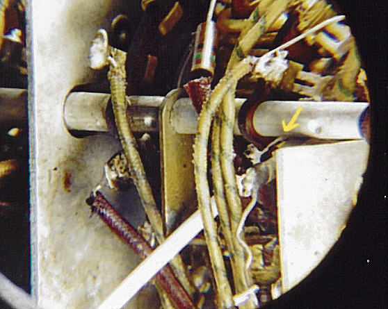
Eventually, however, I discovered that one switch wafer had
been broken completely in half! The break occured right under
the side shafts, so it was tricky to spot. The following photo
shows one break. I slipped a Q-tip behind the break to make it more visible,
and drew in a yellow arrow pointing to it.
Looking at wiring in that area, I figured out how the switch
had been broken. One of the small capacitors behind the
switch had been burned, requiring replacement. Since it was
hard to reach both leads of that capacitor, the repairman
had connected the closer lead to the new capacitor and
brought it out across the front of the switch to
ground on a more accessible lug on the chassis. In the course
of loosening and resoldering this and other components attached to
the switch, he must have yanked hard enough on them to break the
wafer.
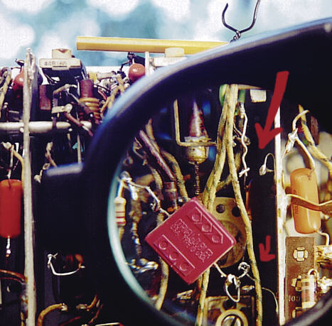
The next photo shows the trouble spot. The large red arrow
points to the place where the damage was caused. The smaller
arrow points to a lower lug where I temporarily reattached
the capacitor. (I'll explain the pencil
with the twist-tie later in this article.)
Amazingly, the part of the switch closest to the outside still
worked. But the part under the rearmost side shaft had
sagged down so far that one terminal couldn't make
contact. The area with the worse problem was also more
difficult to repair—perhaps explaining why previous
owners had given up on this problem.
Repairing a Broken Switch Wafer
The first step in repairing the break was to temporarily disconnect
all the leads from the bottom of the switch, allowing me to raise it
back up. Then I carefully cleaned the entire switch—especially
the breaks—using lacquer thinner, toothpicks, and
Q-tip swabs. The interior of this radio was quite grubby, and
I wanted my glue to adhere well.
Next, I practiced raising the switch into position and
clamping it securely. It took a lot of finesse to maneuver
the loose contact behind the switch back onto the rotor.
Since I planned to use JB Weld epoxy for the repair, I
would have only one chance to do it right!
I mixed the epoxy, applied it to the
breaks, and clamped the switch down, examing the repair
very closely to make sure I hadn't slopped glue onto
places where it shouldn't go. To clamp the whole business together,
I ran a couple of pieces of hookup wire all the way
under the switch, passing up to the top where they
were twisted tight around a pencil. If you look back at the
previous photo, you'll see the pencil-and-wire clamp in place.
I let the repair cure overnight, then used a continuity
tester to find out if my repair was successful. To my relief,
this portion of the switch worked perfectly!
This Concludes the Good News Portion of Our Program . . .
Unfortunately, this repair did not uncover the cause of the
original shorting problem,
and the radio still had a variety of hotwiring left in place
by the last repairman. The next phase of this restoration
seemed to last forever.
Equipped with three different versions of the schematic, I got to know
the SX-42's circuitry, especially its bandswitch, very well.
In the course of removing the repairman's
temporary hotwiring, I also uncovered further problems, each of which
had to be remedied before proceeding further.
The most prominent bit of hotwiring was a jumper wire connecting
the B+ voltage supply of the first RF amplifier tube to the B+
supply of the second RF tube. (Both tubes are type 6AG5, by the
way.)
When I simply removed that jumper, the radio went dead on BC.
Testing the voltage on the second RF tube quickly showed the
reason. No B+ voltage was being supplied.
Fixing this problem involved replacing the components between the B+
line and that tube, and installing a good connection to the 250vdc
B+ line. It's common for aged resistors in such circuits to drift
upwards in value, preventing sufficient voltage from reaching
the tube. The resistors in this circuit were quite far off.
Since the components supplying the second RF tube had tested bad,
I replaced the same components around the first RF tube, for good measure.
I also discovered that another wire had been disconnected from
the very bottom of wafer 7 in the bandswitch. When I reconnected this
wire—Bingo!—the radio played normally on BC. Even better,
now both RF tubes' voltages tested normally. We're making some progress at last!
One Step Forward, One Backward
At this point, I reckoned that I had undone all the repairman's
hotwiring. In doing so, however, I also revived the original
shorting problem with a vengeance. The SX-42 sounded great on the Band 1 (BC),
but the moment I switched
from Band 1 to Band 2, smoke started to rise from the switch and
all-too familiar sizzling sounds were heard. Sigh! The next phase
took a couple of evenings.
By dint of some cautious testing, I determined that the shorting
problem was confined to bands 2 and 3. The radio didn't work very well on
the highest bands, which include the FM broadcast band, but at least it
didn't go up in flames.
Remembering what the repairman had told me, I gave the bandswitch
another magnified exam, in search of any
portion that might be partially or totally burned away. While I was
at it, I gave everything yet another painstaking cleaning,
looking for areas where built-up gunk might have led to carbonization.
I also examined all of the complex, delicate wiring around the switch
in search of places where worn leads might be contacting the chassis
or other components.
A number of frail leads from coils to switch terminals
are insulated with a thin, silky material that is easily burnt or
scratched away in the course of service. If you're not careful while working,
it's also easy to inadvertently nudge these leads to short against nearby terminals or wires.
On the positive side, I confirmed that no contacts or terminals had
been burned up. I also found no crossed or shorting wires.
On the downside, the short was still there, even though every
bit of wiring on the switch seemed to be fine.
Looking back at the email from A.B. Bonds, I remembered his comments
about using a dental scraper to get rid of carbonization. I fashioned
some tiny tools out of scrap wire and metal with my Dremel Moto-Tool,
and proceeded to carefully scrape around every edge of every contact on
every wafer on the switch. My goal was to eliminate any possibility of
hard-to-see carbonization causing an arc between two switch parts.
After the first Evening Of Scraping, finding the magnifying
light inadequate, I invested in a head-mounted magnifying lens, which
could be flipped up and down as needed. (These things make you look like
the world's biggest nerd, but they're good for close-up work.) I also did a
considerable amount
of testing with my ohmmeter, confirming that the switch worked correctly
and tracing various paths in and out of the switch with the aid of
the schematics.
Although no obvious carbonization was uncovered, my confidence in the
switch improved greatly. As far as I could see, it worked perfectly!
The unseen shorting problem still remained, however.
Hitting Bottom
At this stage, it was tough not to feel discouraged. I had spent
many hours replacing components, performing tests, and cleaning and
repairing the switch. But its most glaring problem was as bad as ever
and I was getting awfully sick of messing staring at the cursed thing.
Time for a break! Recalling that the resistors around the RF tubes
had drifted considerably, I began testing and replacing resistors at
other sensitive spots in the radio. In most restorations, I don't worry about
resistors unless they look burned or are obviously the cause of some significant
problem. In simpler radios, there may a considerable amount of design
leeway. Even if many resistors no longer meet factory specifications,
the set may sound fine and play reliably.
The SX-42 is a high-performance radio, however, and I felt that I was
not wasting my time by replacing these components, even if still within
20% or 30% of original specifications. What's more, having already invested
so much labor, I felt a stubborn determination to do this
job right. If I ever succeeded in fixing the bandswitch, the rest of
the radio would be almost like new.
A Spark of Hope
When I returned to the bandswitch, I didn't really have any new ideas.
If all else failed, of course, I could replace the shorting wafer from the
junker chassis as originally planned. But that still seemed like a last resort.
Until I truly isolated the cause of the shorting, I was worried about the
possibility that I might replace that wafer, only to find the short still present.
Even if I would have to replace the whole wafer,
I decided to get as close a look at the spark as possible. I donned
my magnifying goggles, turned off the shop lights, powered up the SX-42,
and (briefly) switched from Band 1 to Band 2.
Bzzzzztttt! Sure enough, it sparked as always, but viewed in the dark with
magnification, I could see exactly where the arc occurred. It was around
pin 10 (back and front) of the bad wafer, in a place where I had noticed a slightly
loose rivet during earlier cleaning and scrape-down sessions. Maybe there was
something there which I hadn't noticed in all my previous examinations.
I hauled my tiny homemade tools back out and made another pass over the
outer surfaces of the wafer. Again, except for some looseness in the rivet,
I couldn't see any carbonization, burning, or dirt.
Then I thought to look in the tiny channel between the
front and rear portions of the switch's central rotor. This is an
extraordinarily difficult area to view, much less to work in, but when I
got a look at the phenolic in that zone, it certainly looked dark.
I spent the next hour or so doing my best to scrape out that channel,
working from every possible angle and rotating the switch through all
of its bands to expose new areas. The black color didn't change appreciably,
nor did the shorting problem. Was this area truly carbonized, or merely
dirty like the rest of the radio when I bought it?
X-Acto to the Rescue
That session was somewhat inconclusive, but I believed that the little
rivet wouldn't have come loose without some reason. At least I had
some new lead to follow.
The next day I went to a hobby shop and picked up a small, curved
hobby-knife blade. It suspected that it might be too large to work well, but
I needed to try something, and there was no place in my town where
I could get dental tools.
Happily, the curved blade worked just fine. Much
sharper and harder than my homebrew scrapers, it removed the
dark material easily. And it was just thin enough to slip into the
cramped working area.
After a few minutes of work, I saw some tiny black chunks
and powder come out of the channel. Paydirt! I had found the charred
area at last. Now I needed to remove all the burned phenolic without
damaging the switch, and then refill it with some insulating material.
Once I had isolated the trouble spot, it it took only a few minutes
to finish removing the black stuff. By the time I was done, the rivet
passing through both sides of the central rotor seemed to be hanging
in space. Unable to see under the innermost part of the
loose rivet, there was no way to tell whether I had gotten all the
bad stuff, but I definitely had reached the point of diminishing
returns with these tools.
Glue, Round Two
For better or for worse, it was time to refill the scraped-out areas.
Although J & B Weld epoxy would certainly be strong enough for this
job, I wanted something more flowable, to fill the tiny cranny
in and around that rivet. The best thing I could
find in my workshop was a gel-type cyanoacrylate, a "super glue" with
strong holding power and the ability to fill in small areas.
Before swabbing it on, though, I wanted to find out whether the glue
was nonconductive. What if, after all this work, I did a perfect bonding
job with a glue that conducted juice better than the charred phenolic?
I glued together two snipped-off capacitor leads, leaving a gap
for the super-glue to fill. After the bond cured, I tested the connection with
my ohmmeter and confirmed that it had infinite resistance.
So far, so good. I didn't know whether the glue would withstand the
high-voltage B+ current that originally caused the arcing, but this
was the best I could do for now.
Taking a long, deep breath, I carefully applied minute drops of glue
inside the switch, pressing them down into the cavity as best I could. After the first
application had dried for about fifteen minutes, I applied a little
more glue in areas that seemed to need it most.
I let the glue dry for an additional period while I reattached the trimmer
capacitors which I had removed to get better access to the switch. Now
for the moment of truth!
The Hour of Decision
If this experiment failed, I faced the daunting prospect of substituting
the new wafer from my junker's bandswitch—several more hours of tedious work
on a switch that I was very, very tired of looking at. I already knew far
more than I wanted to know about the complex pathways through this
gang of wafers.
Before testing the repair, I powered up the radio and tried it on Band 1 (BC).
As before, it worked fine. At least we haven't made things worse!
Turning the voltage down on my variac, I then darkened
the room and cautiously switched to Band 2, watching and sniffing for any signs of
arcing or overheating. Still good. Switching to Band 3, the signs
remained positive. I switched it back to Band 2 and slowly turned up the juice.
Even at normal 117vac voltage, the repair seemed to have worked.
Could it be true? Switching to Band 3, I spun the tuner and was elated to hear
familiar shortwave stations across the dial, including WWV at exactly 10 Mhz.
I let the radio play on those bands for a while longer, to confirm that
my super-glue repair was not going to melt down in a few minutes.
What a relief! After many tedious hours, the bandswitch was finally fixed.
To be honest, my confidence had slipped more than once during this long trial,
but patience and perseverance had payed off in the end. Not only is the bandswitch
restored to proper operation, but now the rest of the radio is in
exceedingly good shape. Between recapping and my "vacation" time to
replace resistors, a large percentage of this 51-year old radio has
been remanufactured just like new.
Had I known the cause of this problem in advance, I could have avoided
pulling the radio's front panel altogether. The repair only required removing
the side panels. I'm very glad that I did pull the front, however. With the
front removed, I was able to check and clean a number of otherwise inaccessible
components.
The Noise Limiter switch was indeed noisy, as A.B. Bonds had
predicted. If that had been left uncleaned, the radio's fine push-pull audio
section would never have sounded as good as it should. The critical Reception
Mode switch was absolutely filthy, and the screw terminals on the S-meter
were also quite loose, causing an intermittent condition. A meter problem
would have been merely annoying, but problems in the mode switch could have
seriously interfered with good reception. Having lavished so much effort on the rest of
this set, I'm glad that those components have been cleaned and brought
back into good fighting trim.
Removing the front panel also will allow me to do a cosmetic restoration,
which I'm more enthusiastic to do, now that I know the electronics are not
unsalvageable. The front panel itself needed some rust removal, or possible repainting,
and the main dial cover had a small crack. I was also
able to do a thorough cleaning and polishing of the fronts of the dials,
and the backs of the dial covers, which makes a great difference when
a radio is as dirty as this one was.
Repairing the Tone Control Switch
A couple of electronic mysteries still remained, after I fixed the bandswitch.
The tone control mysteriously shorted out in the Med and Low positions,
even though all its capacitors and
resistors had been replaced and everything
was connected as shown in the schematic.
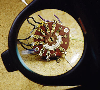
The tone control was easy to fix. Suspecting carbonization, I disconnected
all of the switch's components and removed it from the chassis. Sure
enough—the center channel of its rotor was black, and it had
a burned-out area surrounding one rivet, exactly like the bandswitch.
With more room to maneuver, this switch was considerably easier to
repair than the bandswitch. Within an hour I had scraped out the
black carbon, cleaned everything, polished all the contacts with
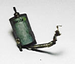
a Dremel Moto-Tool, and repaired the burn with gel cyanoacrylate. The
following photo shows the switch repaired and shined up.
Reinstalled in the radio, the tone control now works fine. I'll normally use
the Hi-Fi or Bass settings for BC and FM listening. For shortwave
and ham listening, however, there are times when the other tone
settings make hard-to-hear broadcasts more audible.
Rebuilding the Filter Capacitor
I also took the time to rebuild the filter capacitor for the power supply.
Although the original capacitors seemed to be okay, giving no hum,
replacing them is a simple matter, and will improve reliability in
the future
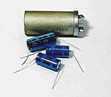
To preserve the radio's originality, I decided to put the new capacitors
inside the original aluminum can, rather than to wire them underneath
the chassis. The next photo shows the replacement units alongside the
can. It will be tight, but the new units should just fit inside.
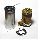
Have you ever wondered what's inside one of those big capacitor cans?
The next photo shows the old foil. Pulling the foil from the can
required removing a retaining ring inside its opening. The ring
won't really be needed later, so I didn't mind bending it.

The simplest way to remove the innards from the can is with a heat gun.
After removing the bottom of the can, screw a big wood screw into the
innards and heat the can to soften the tarry adhesive. Grip the
wood screw with a pliers and pull the innards out in one piece.
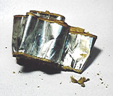
Electrolytic capacitors of this type are known as "dry electrolytics,"
contrasting them with "wet electrolytics" such as the one used in
my Philco 60 Cathedral. The
foil is separated by layers of paper and a chemical paste. Dry
electrolytic capacitors fail when the paste dries out and
allows leakage or shorting between the foil sections. There's
more foil inside than you might think! The next photo shows
the foil partially unwrapped.

Connecting the replacement units requires some careful wiring.
Each replacement capacitor has its own positive lead, and all three
are connected to a common negative lead, just as in the original.
The next photo shows the replacements just before inserting them
in the can. I put spaghetti insulating tubing on each lead,
making sure there would be no unwanted short circuits to the
can.

The can was originally fastened to the chassis with metal lugs
on the retaining ring. Since I was not reusing the ring, I
simply glued the can back on the chassis with a couple of
dabs of epoxy. From the top, the chassis looks completely
original.
Progress on the FM front
That left the FM problem. Since FM coverage was a major
reason to buy this radio in the first place, I definitely wanted to solve
this one! At first, the only obvious anomaly I could find in FM-specific circuits
was low voltages on the 7H7 tubes.
The tubes tested OK, and swapping them around made no change in performance, so I ruled
them out. The B+ voltage supply to those tubes also tested normal, so the problem
must be in some associated component. I replaced all the capacitors and resistors
connected to those tubes, even including those housed in the small IF coupling
coil shown in the next photograph.
I also rebuilt the discriminator coil, one of the coils housed in a square aluminum
shell on top of the chassis. All of this work improved the fidelity in FM, but the
volume was still too low.
In search of new ideas, I sent some email to Walt Heskes,
the designer of the construction projects in our Building
section.
Among other things, Walt suggested doublechecking the values of every component I
had replaced, and resoldering every new solder joint, just in case one of them was
a "cold" joint.
Hauling out the schematic, I began the slow process of finding and verifying the
value of every replaced component, beginning with all those involved in the FM signal
path. Eventually, I hit paydirt. Resistor R40, an IF decoupler, was supposed to be 1.2K, but it had
been replaced with an 8.2K unit.
When I replaced R40 with the correct value, the FM volume immediately increased—a
sign that the too-large resistor had been limiting gain in that IF stage. If you think
about the color codes for those resistor values, it's easy to see how this mistake was
made. The code for 1.2K is brown-red-red, and the code for 8.2K is gray-red-red. No
doubt the original gray had faded to a brownish color, and either I or some previous
repairman had replaced the unit by looking only at the original resistor's color code,
without doublechecking its value against the schematic.
That's a mistake that I won't make in the future. Virtually all old radios have
had some service in the past, and it's not uncommon to find mistakes of various
sorts. "Take nothing for granted" is an excellent motto in radio repair.
The next time I do a full restoration of such a complex receiver, I'm going
to keep a little journal, writing down the value of every replaced component
as I go.
Rebuilding the Reception Mode Switch
Another potential trouble spot is the SX-42's Reception Mode switch, which selects
among Phono, FM, AM, and CW (code) modes. Given the troubles I had found in
other switches, I felt it was worth the time to take out this switch and
clean it up. Although the switch itself is comparatively simple, getting it in and
out of its cramped space is quite a chore. If you have an SX-42 that is working
reasonably well, I would not pull this switch out just for the heck of it!
The Reception Mode switch is one of six controls on the
right of the front panel. It lies in the middle of the top row of three.
The following photo shows the switch after I had loosened its mounting
screw and pushed it back from the panel, but not removed any wires.
To get better access, I also loosened and pushed back the Crystal Phasing control,
which is mounted to the left of this switch.

Most of the wires connected to the switch run down beneath the chassis to
various destinations. There are two resistors wired onto the switch, one
going to ground and the other connected to the Pitch Control switch to the
right. Unsoldering this stuff was a tedious chore, which you must do from
the top down. After top connections are loosened, you can free up the switch
enough to reach connections farther down.
To simplify reassembly, I made a diagram of the switch showing both sides
of both wafers, indicating the wire colors for each terminal and the
thing that each one connects to.
Once the switch was completely unwired, I disassembled the two wafers
and cleaned every contact carefully. After taking off all gunk with
lacquer thinner and Q-tip swabs, I gently polished the contacts with
a soft metal brush attached to my Dremel Moto-Tool. The next photo
shows the clean switch ready to reinstall.

Reinstallation sounds simple, but this procedure involved one more unexpected detour.
After taking the previous photo, I happened to drop the switch
on the floor. Picking up the switch, I pulled out my diagram
to review once again exactly how I would rewire the switch. As I
turned the switch back and forth to compare it to the diagram,
I noticed something horrifying—part of the switch was missing!
Slowly, it dawned on me. Dropping the switch must have broken it.
Grabbing a flashlight, I scrabbled under my workbench and quickly
found the missing part. Half of one wafer had broken off, right next
to the mounting screws which hold the wafers together. Grrrr!
Fortunately, the breaks were clean and nothing seemed to be missing.
I got out my JB Weld epoxy and glued the wafer back on, clamping
it carefully. After curing overnight, the switch seemed to
be operational and solid, so I wired it back into the radio,
referring to my diagram as well as the schematic and testing each
connection for continuity as I worked.
When I powered up the radio for a final test, another seeming problem arose.
The radio seemed to be completely dead! Not even a faint background
hum came from the speaker, and switching from one mode to another
had no effect. After all my precautions, could I possibly have made
some bonehead mistake in rewiring the switch?
At times like this, it helps to get a fresh cup of coffee and clear
the mind before going any further. When I returned to my shop with fresh coffee, I
instantly saw the source of the problem. The 6SL7 audio inverter tube,
which I had removed to get better access, was still lying on my
workbench. I popped the tube back in its socket, powered up the radio,
and was relieved to find that the switch worked perfectly. Whew!
Death By a Thousand Cuts
Although the FM was noticeably louder than before, the volume still was only about half as loud for strong
local FM stations as for strong local AM stations. And the S-meter's response
was still weak on FM.
Both Walt and A.B. Bonds had suggested that realignment should improve the FM, so I hauled out
my signal generator and multitester and went to work. Not having done this before,
it took a couple of tries, but eventually I got another significant gain in
FM volume as well as better fidelity.
Given the number of replaced components, it seemed possible that the RF stages
needed alignment, too. When I began this process, I discovered yet another problem
in this 52-year old radio.
The antenna coil for band 6, which covers the FM broadcast frequencies, was
partially broken. The slug (core) of that coil is made of ferrite, a rather
fragile substance. The top of the slug is slotted all the way across, allowing
you to turn it with a screwdriver. Half of this slotted top was broken away,
making it impossible to align that coil.
Who knows, perhaps this problem accounts for the remaining lack of gain on
band 6. Unfortunately, this will not be simple to fix. My junker SX-42
chassis has a perfectly good antenna coil that I could substitute for the
broken one. But that coil is buried within the complex bandswitch, and
replacing the bad one will mean removing and reinstalling a lot of extremely
cramped components.
Fixing the FM section of this radio has been a "death by a thousand cuts" type
of experience. It was not one dramatic problem, but a combination of
several small problems that, in total, degraded the performance. While the
radio is listenable on FM, it still pales in comparison to its AM performance.
Meanwhile, the performance of this receiver in AM mode is breathtaking.
The SX-42 is truly an outstanding shortwave receiver. Now if I can only get the FM
to work properly!
Replacing the Antenna Coil
Looking more closely at the broken antenna coil, I figured out a way to replace
the slug (turnable core) without unwiring the whole coil. The slug has screw slots
on both ends. Although the top slot in the ferrite core was broken, the bottom
end is a long brass screw that fits into a metal cap.
If I could somehow unscrew the slug from that end, I could pull it
out and replace it with the good slug from my junker chassis.
It was a tight fit, but by taping my smallest screwdriver to the end of another
screwdriver, I was able to reach up and past nearby components to unscrew
the slug. Once it was completely loosened, the slug didn't just pop out of the coil shell, however,
and the broken top offered nothing to grab onto. I even tried turning the radio
over and shaking it, but the slug still refused to drop out.
Where there's a will, there's a way. Cutting off one end of a Q-tip
swab, I glued its shaft to the broken slug with a dab of gel-type cyanoacrylate glue.
After holding it in place for 15 seconds to set the glue, the slug came out
easily. Screwing the new slug into place took only a second or two.
With a good antenna coil in place, I repeated the RF alignment steps for
band 6, and also repeated the 10.7 Mhz IF alignment steps, including the FM
adjustments. For the first time, I was able to get a clearly defined "null"
spot as indicated in the FM procedure. The FM reception is slightly better
than before, but still somewhat weak compared to AM. After I clear
out some other projects, perhaps I'll do another FM alignment
and see whether further tinkering improves the reception. One
thing I've noticed is that the type of antenna connected makes
a big difference for FM.
Cosmetic Restoration
Restoring the cosmetics turned out to be simpler than I had imagined. The front panel had a number of small rust spots, and
looked generally dingy, but the lettering was intact and it
had no major scrapes.
I began by removing the rust with Naval Jelly, which is simply
a solution of concentrated phosphoric acid (found in Coca Cola and
other soft drinks). I sprayed on a layer of jelly, waited for an
hour or two, then rinsed it off with water.
The appearance was vastly improved. The former rust spots all
seemed to disappear into the grey-colored paint. Declaring victory,
I gave the front panel a nice rubout with Novus Plastic Polish
#2 to remove remaining surface grime and shine it up. It's not perfect, but from six feet away you couldn't distinguish it from
a freshly repainted panel.
The main tuning dial cover also had a crack in it. By main
cover, I mean the large black lower portion of the dial cover.
Repairing the crack was also straightforward. After carefully
cleaning the cover, I mixed up
a little bit of Plast-T-Pair repair mix, then dabbed it
into the crack. After the repair had cured, I wet-sanded that
area with 800 grade paper until the repair was invisible.
After I was done, I discovered that I could see through the
clear repair material, all the way through the cover. The
original plastic was opaque black, while the repair plastic
was translucent.
The remedy was to mask off the clear portion of the dial and
paint the front with gloss black paint. I gave it a couple of
coats of paint, wet-sanding between coats, and then gently
polishing out the final coat with Novus Plastic Polish #2.
When I was done, the dial cover looked just like new.
SX-42 Goes to the Movies!
With that, the restoration saga drew to a close and I commenced
to enjoy my SX-42, playing it from time to time during the next
16 years.
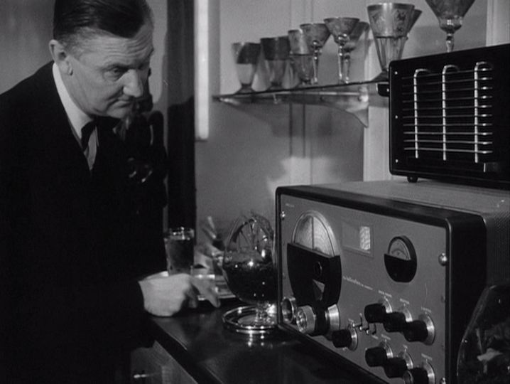
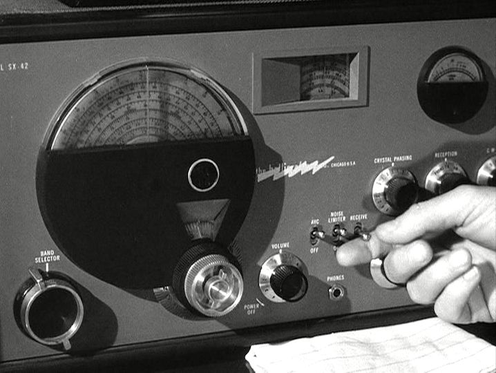
In 2014, we happened to watch The Unsuspected,
a 1947 noir thriller starring Claude Rains as a murderous radio host.
To my surprise, the film featured an SX-42 radio in a few scenes, which appear below.
Early in the action, the villain's butler tunes in a broadcast on the
SX-42:
Notice the speaker on top of the radio. It looks like a prop designer
used the lower grille from a Hallicrafters PM-23 speaker on a cut-down cabinet.
The PM-23 was the correct matching speaker for the
earlier line of Hallicrafters receivers, models SX-25 through SX-28, and you can see one
in this photo of my SX-28:

As you can see, the PM-23 is considerably bigger than the speaker in the
film, but we can forgive the designer for wanting something a little sleeker.
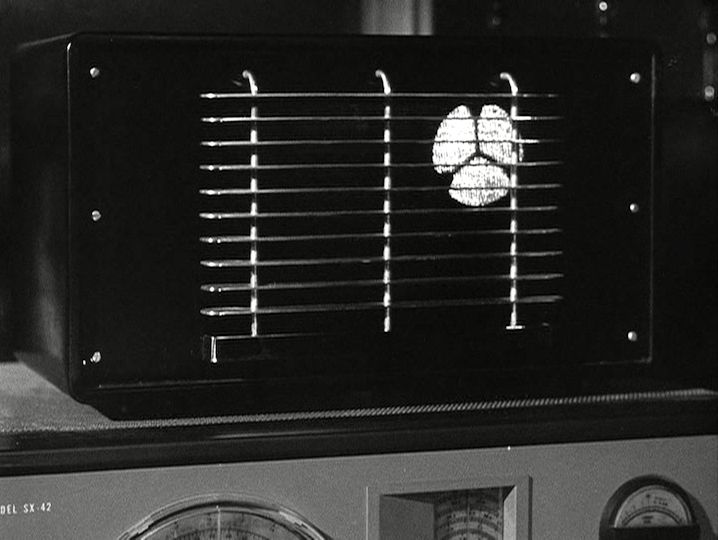
Later in the film, the villain covertly flips a switch
to activate his hidden recording setup. His plan is to record the conversation
of two other people in the room. Notice the little lightning
bolt that shoots out of the radio dial, another bit of movie magic:

After he flips the switch, a mysterious light appears inside the speaker to
indicate that it is now acting as a microphone:

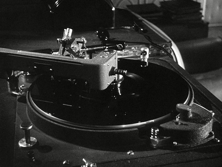
He races to another room where he records their conversation on
an elaborate turntable. Notice the jumbo 16-inch platter:

Meanwhile, the evil couple continues their incriminating conversation, little knowing that
it is being recorded for later use in the villain's dastardly scheme:

Of course, we all know that an SX-42 can't be used in this fashion, but it makes
a pretty convincing prop if you don't think closely about the details!
|