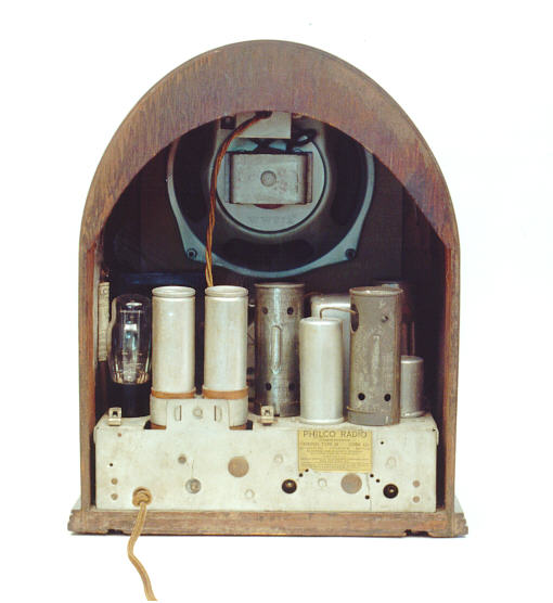
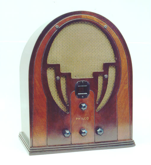
Philco Model 60B Cathedral Radio (1935)


I picked up this Philco cathedral radio during a family vacation
in the Summer of 1997.
This is a large tabletop set, measuring 16 inches high,
11.5 inches wide, and 8.5 inches deep. In a house already
crowded with radios, we don't have room for too many
of this size, but I had always wanted one cathedral set
for my collection, and this one's a dandy.
Cabinet Restoration
The cathedral style of cabinet was wildly popular during the 1930s, and Philco
sold many thousands of them. Built in 1935, this Model 60B is typical
of the breed: not as ornate as some models, but with clean,
elegant lines.
As purchased, the cabinet was quite presentable. It had
only a few light scratches, a couple of small paint
splotches, and a lot of microscopic paint dots.
It also was missing one knob. It's hard to find replacement
knobs for many radios, but I was able to get an exact replacement
from Antique Electronic Supply
for only a few dollars.
The first step in reviving the finish was to gently clean the entire
cabinet using #0000 steel wool and paint thinner (mineral spirits).
This removed all traces of old furniture polish and other gunk.
It also took care of the paint splotches and most of the
dots.
To remove the tougher dots, I let them soak under
thinner for a few minutes, then rubbed them off with a thinner-soaked rag. This trick will work for any latex-based paint. You
can also use "Goof-Off 2" cleaner.
The next step was to touch up the scratches.
I used a Min-Wax product called a
"wood finish stain marker," which is simply a pen
containing stain instead of ink. The thin, chisel-shaped fiber point
lets you get a small amount of stain into
a scratch without darkening the surrounding wood too much.
After treating each scratch, I let the stain set for
a few seconds, then wiped it with a soft cloth to remove any
excess and blend in the edges, if needed. Min-Wax stain
markers are available in a range of colors;
#2716, Dark Walnut, was a good match for this cabinet.
At this stage, some folks would spray on a coat of
clear lacquer, but I didn't bother. The cabinet looks
great, just like a well-preserved original.
The grille cloth is faded, but still pretty decent, with only
one tiny puncture wound near the bottom. Perhaps I'll replace
it some day, but it seems fine for now.
Other than cleaning dust from the interior, that's
all it took to spiff up the cabinet. I didn't keep track
of the time, but this part of the project probably took
no more than two or three hours.
Electronic Restoration
Prior to this, I had never restored a 1930s radio, so this part
of the project offered a chance to get more familiar with
electronics of this era. Here is a description of the
electronics from the Philco service sheet:
The Philco Radio Model 60 is a five-tube superheterodyne receiver,
operating upon alternating current and designed for the reception
of standard broadcast, and police, airport and aircraft, and
amateur radiophone signals. The frequency range is 530-4000
kilocycles. The intermediate frequency is 460 kilocycles. The
power consumption is 60 watts. A Type 6A7 tube is used as a
combination first detector and oscillator, a Type 78 for intermediate
frequency; a Type 75 as a second detector and first A.F.;
a Type 42 as second A.F. (output), and a Type 80 as a rectifier.
You can download the schematic and service data at the
Nostalgia Air
website. Click on the Resources section and locate Philco
Model 60.
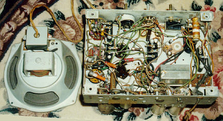
The following chassis photos show the radio before restoration. There was
plenty of dust on top. The underside was much cleaner, of course.
As old radios go, this one is pretty easy to work on.
The chassis is not too cramped, and the color
coding on the wires is still clearly visible. (In case you're
wondering, the speaker cone is not damaged. The lines that you
see are the original glued seam in the cardboard and a chalk stripe
whose purpose I don't understand.)
Rebuilding Wet Electrolytic Capacitors
When I purchased the radio, it was evident that I
shouldn't even attempt to apply power.
Under the chassis, two large can capacitors had leaked some kind of
gunk that left big hard blobs of corrosion on their terminals.
The capacitors showing the corrosion are both 8-mfd units, which
serve as filters for the power supply.
These are "wet electrolytic"
type capacitors, containing a weak solution of boric acid similar to what
is used in eyedrops. The electrolyte forms a film over the internal metal
components, keeping them electrically insulated. Over time,
the electrolyte leaks out and evaporates, usually leaving a tell-tale
crust behind. You should never just power up an unrestored radio with
this type of capacitor. The capacitor is certain to be bad.
The can filters are mounted in cardboard sleeves, standing
upright inside a dual clamp. They are easily visible left of center in
the rear chassis view. A single setscrew in
the middle of the clamp holds both cans tight.
Although you could simply disconnect these capacitors and wire
new units in their stead, I wanted a more authentic
restoration, which means taking out their innards and hiding
new capacitors in the original cans. Choosing the capacitor with less
corrosion, I unsoldered its two wires, pulled the whole unit out of the clamp,
and slipped off the cardboard sleeve.
When I removed the capacitor from the cardboard sleeve, its outer
terminal fell loose. This terminal is
a small metal strip, bent with a little jog in the middle.
When installed, the strip is held between the can and
the sleeve by the tightened clamp (there is no soldered connection).
The bend in the terminal fits against a slight lip in the sleeve,
further helping to keep the terminal in place.
The next step was to cut the bottom (terminal)
end from the can and remove the innards. I used a Dremel
Moto-Tool with cutting disc to carefully slice off
the can end; a hacksaw would work just as well. As soon as
I pierced the can, the last remains of the electrolyte solution
drained out.
Inside the capacitor, connected to its center terminal, is
a big spiral of aluminum, perforated with oblong
holes. The spiral forms one element of the capacitor, and the
can acts as the other. Insulating the spiral from the can is a
dark-colored mesh liner.
The center terminal is insulated from the can end with
a rubber gasket. In this case, the rubber had dried and cracked over time,
leaking some of the solution and causing a crumbly buildup of
dried chemicals.
After removing the end, I washed
the can parts with hot water and a soapy brush.
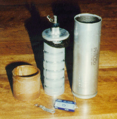
The next photo shows the capacitor with its innards exposed.
The terminal end is still attached to the inner spiral. The
cardboard sleeve and outer terminal lie next to it, along with
the replacement capacitor. To the right is the can body,
with its insulating mesh still inside.
Although the spiral is a nice piece of old workmanship,
it had to go, to make room for the replacement unit.
Using a thin hacksaw blade, I cut the center terminal connector
on the inside of the can end, leaving a long stub to provide
a connection point for the replacement capacitor.
For the replacement, I chose a new 10-mfd electrolytic capacitor, which
I happened to have on hand.
Its value is slightly larger than the original 8-mfd unit, but
the difference won't matter in this application.
The new capacitor was so much smaller than the old spiral
that finding space for it was no problem. Making a good
connection was not so easy. The can is made of aluminum,
which doesn't accept solder, so I improvised some mechanical connections.
I used the Dremel tool to cut a thin slot in the end
of the center terminal stub, then I placed one capacitor lead in the
slot and crimped it tight. I wanted to reuse the original outer terminal,
which meant that the other lead needed to connect to
the can body itself.
Lacking any better idea at the time, I left the
lead as long as possible, bent it to lie flat against the
inner surface of the can end, and tacked it in place with some
blobs of solder. I then covered the tacked-on lead with some hot glue
to strengthen the bond. I'd prefer a stronger
connection, of course, but since this will
be sealed inside a metal can, I hope it will stay in place.
I suppose you could also drill a hole in the can end and
run the lead out through there, if you don't mind the slightly
less authentic appearance.
Before replacing the can end, I
carefully checked the new connections for continuity. Everything
seemed fine, so I glued the end onto the can with JB Weld epoxy. The
thin joint will be completely concealed after
the can is back in its cardboard sleeve.
The second capacitor was rebuilt in the same way.
This one had shown a much bigger blob of gunk around
its terminal: exactly one can's worth, as it turned out.
It was completely dry inside.
When I reinstalled the cans in their clamps, I turned them so
that their printed Philco labels are visible.
Powered up with fresh filters in place, the radio
played weakly, but obviously still needed more service.
Cleaning the Tone Control
Every old radio can stand some cleaning of its electro-mechanical
components such as the volume control, tone control, or bandswitch.
Dirt or corrosion inside a bandswitch interferes with the
incoming signal, which can make a radio play faintly or
silence a band completely. Gunk in a volume control or tone
control interferes with the audio output. Inspecting and
cleaning these components is a routine
part of every restoration.
The next photo shows the three main controls in a Model 60B,
as well as a "Bakelite block" capacitor, about which more
in a moment. From left to right, the highlighted items are the block capacitor, the volume control, the bandswitch,
and the tone control.
This Philco's tone control is a simple two-pole switch
mounted on a small metal case, which is filled with some hard black material.
Sealed inside the black stuff are two capacitors,
one .01-mfd unit and one .015 unit. The larger, .01-mfd capacitor
is always connected, according to the schematic. Flipping the
switch connects the .015-mfd capacitor in parallel with the
larger one, increasing the total capacitance and affecting the
signal delivered to the audio output transformer.
Capacitors sealed within blocks are a hallmark of 1930s Philco radios.
This tone control is a specialized application, combining
a switch with two capacitors, but Philco also used this technique in cases
where other manufacturers used individual capacitors.
The leftmost highlighted item in the
closeup shows a typical Bakelite block
capacitor. You can spot several more in
the chassis interior.
These units all look almost identical: black cases with
rounded corners and large connecting terminals on top.
Antique Electronic Supply
sells an entire book about these beasties.
Cleaning the tone control took about 90 seconds. I gave its exposed
terminals a quick shot of spray cleaner, then worked it briefly and
wiped off the excess with a clean cloth. The result was a noticeable, although not dramatic, improvement in the radio's sound.
Cleaning the Bandswitch
Next in line was the frozen bandswitch, which took considerably
more effort. Trying to shoot some solvent down into the shaft
had no effect, so I had to disassemble it. Looking inside the
chassis, I could see that there would be enough room to slide
the shaft backward, once freed, so I decided to work on
it in situ rather than unsolder its connections and remove
it from the chassis.
This shaft is held in place by two split collar washers that
fit into a slot in the shaft, just outside the threads for the chassis mounting nut.
Using a pick and a tiny screwdriver, I spread the outermost
washer far enough to grab one side with a
small pliers. Then I was able to spread the washer further and
work it off the shaft. Lying under the first split washer was a smaller
one, which I winkled out of the slot and removed in the same way.
Turning the chassis
so that the shaft stood upright, I shot a bit of WD-40
solvent down the shaft.
After giving that a minute to work, I gently pushed and turned
the shaft, which slowly but surely loosened up.
Once free, the shaft could be pushed straight back toward
the chassis interior about one
inch, allowing me to clean the exposed inner portion of the
shaft with a solvent-moistened Q-tip. There was no trace of
corrosion inside. The original lubricant had simply
dried out.
Dried lubricant is another very common condition in
elderly radios and phonographs. It's a good idea to play
every old radio periodically, to move the lube around a
little bit and keep things from freezing up.
While I had the switch apart, I cleaned all of its contacts
very carefully. Then I lubricated the shaft
with light oil and pushed the switch back into
place, checking its action before reinstalling the collar washers
on the shaft.
With two of the three controls cleaned up, the radio
sounded significantly better.
At this point it was nearly suppertime, so I slipped the radio
back into its cabinet and brought it into our dining room,
to provide some dinnertime music. I also wanted to let it run for
a longer period, to see what happened. During this and previous tests,
I powered the radio through my variac, which lets you adjust
the voltage to the power supply. After slowly bringing up the
voltage, I ran the radio at about 100 volts,
which is lower than normal line voltage, but usually sufficient
to let a tube radio operate. It sounded great for a while, but later the
sound faded out and become scratchy.
Since we were still eating dinner, I powered
the radio down for the night.
The next day,
I sent a query to the
rec.antiques.radio+phono newsgroup,
asking for advice on possible causes of fading volume.
As I learned from the replies, they are legion.
Here is one response from Al Welch:
In old radios that fade after 30 minutes, the problem is often due to
resistors connected to cathode or grid pins that have shifted upward in
resistance value. Other possible causes are hidden defects in converter
or output tubes, defective output transformer, weak rectifier or a
faulty speaker. It's a tough one because you have to wait 30 minutes to
see if the problem will appear again. Signal injection and tube voltage
checks, before and after the problem sets in, may be necessary to locate
the cause. A signal tracer that checks the speaker might be helpful.
Peter Bertini, an editor at Communications Quarterly
magazine, had this to add:
There could be any number of causes for that problem.
I would replace the coupling cap to the grid
of the audio tube for starters.
At this point, I still hadn't cleaned the volume control, so I filed
this information away for the time being. It's always good practice
to eliminate the obvious before looking at more subtle causes.
Cleaning the Volume Control
The next day, I found time to clean the volume control.
This control didn't exhibit any loud scratchiness or
"dead spots," but you would expect it to have some dirt and
corrosion inside, after sixty-odd years in service.
Many modern variable resistors have little openings somewhere,
large enough to spray in a little cleaning solution.
This particular unit was well sealed, however, using little
metal tabs all around the edge of the can-shaped body.
I actually ended up cleaning this control twice. The first time
around, I tried the lazy man's way: loosening a few tabs
around the can so that I could pry it open far enough to shoot
some cleaner inside.
I was able to do this without unsoldering the control, by simply removing
the mounting screw and pushing the control backward into the
chassis. (Are you getting the idea
that I don't like disturbing original components unnecessarily?)
The first application of cleaner seemed to make a big improvement.
The radio played more powerfully, and its tone was much better.
Hoping I had solved the problem,
I set up the radio in our living room and played it for a while,
to see whether the fading problem would reappear.
For a while, it seemed like I was home free. Playing for several hours over
two or three days over New Year's, the radio sounded great. One
evening, however, I sat
down to play a card game with my kids in the living room. Just for fun,
I set up my flea-powered AM radio transmitter to
broadcast an episode of the old Superman radio show through this radio
during our game.
You guessed it! Everything sounded peachy for about half an hour, then
the volume faded and became scratchy. One jiggle on the volume control
identified the culprit—it made an obvious scratching noise—so,
after we finished our card game, it was back to the shop again.
Okay, no lazy-man's shortcuts this time. I unsoldered and removed
the volume control, disassembling it
completely for cleaning. Inside this control, a little brass
pad slides around on a disc of black resistive material as you
turn the shaft. I cleaned all of
the working surfaces carefully, using electronic cleaner and a
fine, lint-free cloth wrapped around the end of a small screwdriver.
That done, I put the control back together and reinstalled it in the radio.
Powered up on the bench again, the radio sounded fine at all volumes.
Playing for an hour or more, no amount of jiggling or pushing on
any control produced the slightest amount of noise.
Here's a photo of the radio at this stage.
(By the way, this is not where I normally work on radios.
Due to some remodeling and general holiday mess, I was temporarily evicted
to a table out in our garage. Behind the table you can see through a window
into the corner of our little greenhouse.)
Tuning Capacitor Tweaks
Sensing that the finish line was near, I took care a few
miscellaneous tasks that
I had been putting off until the electronics sounded good.
One item needing more attention was the tuning capacitor.
This tuner differs from modern ones in a couple of ways.
Instead of a stationary dial and a moving pointer, it has
a stationary pointer and a moving dial. Using no pulleys or
strings, the knob and dial are both mounted directly on the
shaft of the tuning capacitor, and turn together (see the
chassis photo). Lit from
behind, the pointer casts a shadow behind the translucent
yellowish-orange dial.
The tuning capacitor's mounting bolts are cushioned under the
chassis with thick rubber washers.
In this set, those little rubber cushions
had shrunk with age, which made the whole tuning
mechanism—capacitor, dial, and knob—slightly wobbly.
If you look carefully at the cabinet photo,
you can see a faint scratch behind the tuning knob, evidence that the wobble
had existed for a while. I had taken some pains to conceal this scratch
when restoring the cabinet, and I didn't want to reopen that wound.
It took only a few minutes to loosen the mounting screws
and install new rubber grommets in place of the old rubber washers.
I had previously given the tuning capacitor a quick cleanup and lube,
but it still didn't work as smoothly as I'd like. Looking closely into
the main ball bearing, I could still see traces of dry,
blackened lubricant. Using a solvent, I cleaned up all the bearings
and lubricated them again. To clean in tight corners like this,
you can snip the shaft of a Q-tip to a point, making a cleaning
tool that won't scratch anything or leave lint behind.
Now the tuner felt solid and smooth. Much better than before!
Final Touches
Before putting the radio back in its cabinet, I glued
down a couple of loose corners on the paper labels.
And, finally, I cut little circles of dark brown felt to go
between the inner surface of the control knobs and the newly restored
cabinet. I don't know whether this radio originally used such felt
washers, but these will help protect the cabinet as well as keep
dirt away from the control shafts.
Final Thoughts
This was the oldest radio that I had restored up to this time, and I was pleasantly surprised with its performance. Lacking some modern
refinements such as AVC (automatic volume control), it is nevertheless
an excellent-sounding radio, with good fidelity and plenty of
volume to fill the room.
Some day, I should take this radio back into the shop and invest the effort to
replace the Bakelite block capacitors. That's a messy procedure, but it
should be done to guarantee reliability over the long term.
Since the writing of this article 20+ years ago, the old USENET newsgroups
such as rec.antiques.radio+phono have been replaced by
newer web-based discussion forums, like those mentioned in my
Discussion Groups page.
|

