Hallicrafters Model SX-28 Communications Receiver (1941)


One of the most beloved of all communications radios, Hallicrafters' Model SX-28, dubbed the Super Skyrider, was sold from 1941-1944 and was their top-line receiver. Many thousands were manufactured for government service during World War II, so this radio has historical significance and is also fairly plentiful.
This article contains a detailed account of how I restored my SX-28, with a number of photos, so please be patient while it loads. You can click on any of the thumbnail images on this page for a larger view.
Description
Model SX-28 was Hallicrafters' finest receiver during the years 1940-1944. It originally sold for $159.50. During the wartime years, Hallicrafters introduced Model SX-28A, essentially the same receiver with minor modifications in the RF section. By 1944, the SX-28A sold for $223.
This Hallicrafters ad from 1944 shows the SX-28 and tells
people that "the time will come" when they'll
be able to buy such a fine receiver. (During World War II, all domestic radio manufacturing was diverted to military production.)
The radio was also manufactured under the model number SX-28A-FCC, indicating radios made for the Federal Communications Commission, and the military model number AN/GRR-2. Tens of thousands of SX-28A and AN/GRR-2 receivers were manufactured for wartime use, so you're more likely to find one of those than an "original recipe" SX-28 such as mine.
The next photo shows my restored SX-28 in its cabinet,
with matching PM-23 speaker.
This style of cabinet, sometimes called the Gothic, is somewhat scarce because many radios were rack-mounted. A rack-mounted set usually had a smaller rectangular cabinet, or none at all.
Hallicrafters offered two matching speakers for the SX-28, the model PM-23 shown above, and a large wooden console speaker, model R-12. Most PM-23 speakers do not have the chrome lowercase "h" logo.
As with many communications receivers, the matching speaker is harder to find than the receiver itself, since the speaker was an extra-cost option and many owners chose to use other speakers or headphones. If you have a big R-12 console speaker, hang onto it! They are quite rare.
The Super Skyrider name was used for several of Hallicrafters' high-end receivers during the 1930s and 1940s. The company used Sky in several other names, including Sky Challenger, Sky Buddy, Sky Champion, Sky Ranger, and even Skyrider Jr.
The SX-28 is a general-coverage AM receiver, covering the frequencies .54 - 44 megahertz in six bands. Special features include variable sensitivity in three stages (sharp, narrow, and broad IF), BFO, a crystal filter for CW (code) listening, automatic noise limiter (ANL), automatic volume control (AVC), a calibrated bandspread tuner, antenna trimmer, and an S-meter to indicate signal strength.
The push-pull audio amplifier uses two 6V6 output tubes, giving excellent audio quality. The audio section includes a bass boost switch in addition to a variable tone control. A phono jack in the back allows you to play an external source such as a record player through the amplifier. A headphone jack is provided on the front panel. On the back panel are two sets of speaker terminals, for a 500-ohm or 5,000-ohm speaker.
The Receive/Standby switch on the front panel is for use with a transmitter. When you switch to Standby, most of the receiver is turned off, but the tube filaments are kept under power, allowing the set to come back almost instantly when you switch back to Receive.
Hallicrafters made a number of small changes during the SX-28/SX-28A production run. Some sets have an inline fuse on the back panel; some have a rectangular AC outlet on the back panel.
These minor differences do not indicate whether you have an SX-28 or SX-28A. The only sure identifier is the type of coils used in the RF section, which are visible under the chassis. If the coil forms are round, as in my set, it is an SX-28. If they are square, the radio is an SX-28A. Note that some SX-28A sets say SX-28 on the front panel, while others say SX-28A, so even that is not a positive way to ID your set.
Here is a list of the SX-28's fifteen tubes.
|
Tube |
Type |
Function |
|
V1 |
6AB7 |
1st RF amplifier |
|
V2 |
6SK7 |
2nd RF amplifier |
|
V3 |
6SA7 |
Mixer |
|
V4 |
6SA7 |
Oscillator |
|
V5 |
6L7 |
ANL/1st IF amplifier |
|
V6 |
6SK7 |
2nd IF amplifier |
|
V7 |
6B8 |
Detector/S-meter amplifier |
|
V8 |
6B8 |
AVC amplifier |
|
V9 |
6AB7 |
ANL amplifier |
|
V10 |
6H6 |
ANL |
|
V11 |
6J5 |
BFO |
|
V12 |
6SC7 |
1st audio amplifier |
|
V13 |
6V6 |
Audio amplifier |
|
V14 |
6V6 |
Audio amplifier |
|
V15 |
5Z3 |
Rectifier |
The AVC (automatic volume control) circuitry in the SX-28 is more complex than usual. It has two AVC circuits rather than the usual one. One circuit regulates the first IF amplifier, while the other regulates the RF amplifiers and the second IF amplifier.
First Look
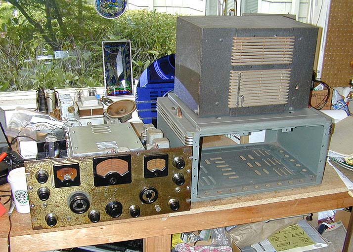
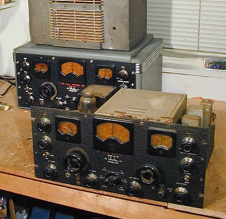
The following photo shows my SX-28 on the day of purchase. To the right of the chassis are its empty cabinet and a matching PM-23 speaker that I had bought the previous year.
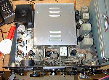
The next photo shows the top of the chassis.
The seller of my SX-28 had owned it for 31 years and used it much of that time. The set was well cared for, but showed an average amount of corrosion on the chassis. Some previous owner had stripped the paint from the front panel and then applied a coat of orange shellac to the panel as well as all of the knobs.
I paid $150 for the receiver and cabinet, which seemed like a fair price to me. My cabinet has good paint, but a previous owner had added two chrome carry handles on the top. I will need to remove those handles, fill the holes, and apply a little touch-up paint to make the cabinet look authentic.
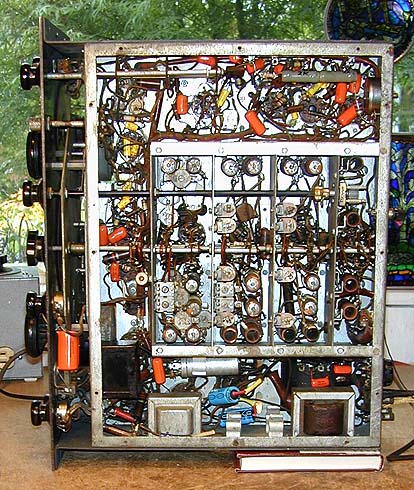
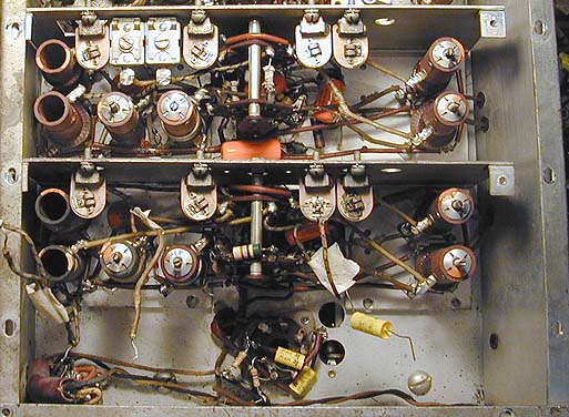
The following photo shows the underside of the chassis before restoration. The SX-28 uses dozens of paper capacitors and half a dozen electrolytics. All of those sixty-year old capacitors are candidates for replacement. Mixed in with the original paper caps, you can see a few disc ceramic and plastic-coated units, indicating that this receiver was serviced more than once over the years.
My radio also had a non-authentic bandswitch knob at the time these photos were taken. The original knob has two
large rectangular "ears" and the lowercase Hallicrafters "h" symbol in the center. A couple of years after I
wrote this page, I obtained the correct knob from a fellow collector.
Electronic Restoration
The SX-28 is a difficult radio to restore. Its electronics are cramped and there are many small components to replace and check. Aligning the receiver is a complex, highly exacting process. If you are novice repairman, it's better to cut your teeth on a simpler set such as a Hallicrafters S-38 or S-20R,
or even a five-tube "All-American Five" tabletop radio.
When I bought my SX-28, it was in nominally working condition. It received signals on all bands; and other circuits such as the BFO, ANL, and crystal filter, seemed to be in basic working order.
The only obvious problem was an unresponsive S-meter. On a working meter, the needle rests all the way to the left when there is no signal (for instance, if you disconnect the antenna). As you tune in a station, the needle moves to the right. On my set, the S-meter needle rested barely to the left of the rightmost point at no signal, and barely twitched when tuned to a strong station.
Since the S-meter is potentially affected by many different parts of the radio, I decided not to worry about it until I had finished all of the basic service and knew that sections such as the RF, IF, and AVC, were in good working order.
As with all radios, I began by cleaning off all the dirt, checking the tubes, and cleaning and lubricating all controls and other moving parts. A few tubes tested weak, so I replaced them at once.
Lucky for me, the seller had included a big box of replacement tubes, which he inherited from a previous owner. I hadn't paid much attention to the contents of the box at the time, since I already own several hundred tubes. I was pleasantly surprised when I checked it out at home, however. The box contained over fifty tubes—enough to keep the SX-28 running happily for decades to come.
When you clean up an SX-28, use caution around the dials. The dial material is brittle and it's easy to scrape off the lettering if you clean too enthusiastically.
Another weak spot is the complicated mechanism for moving shadowed pointers up and down behind the dials, to show which band you are receiving. Strings coming off the bandswitch shaft drive these pointers. To reduce pressure on the fragile bandswitch knob, and the rest of this Rube Goldberg-ish contraption, you should carefully clean and lubricate all of the little pulleys and wear points, as well as the bandswitch itself.
Another basic step is to replace the old line cord with a new three-wire grounded cord. While you're
at it, that's a good time to replace the two bypass capacitors on the AC line (C51, C52).
Following the preliminaries, I began the long process of replacing old paper and electrolytic capacitors. On a radio this old, you can be certain that many capacitors will be leaking or shorted. Even those that test OK at the moment are likely to fail before long, so it's not worth the risk of keeping them in the receiver. For more details on recapping, see
Replacing Capacitors in Old Radios.
I started by replacing all of the easily reachable capacitors. As I replaced each one, I checked it off on the parts list and marked it with a colored highlighter on a copy of the schematic. I don't always document my restorations, but this radio is complex. If you keep track of what you're doing, it's easier to backtrack if you make a mistake. It's also easier to troubleshoot remaining problems when you can verify which circuits have already been checked out.
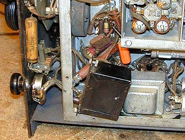
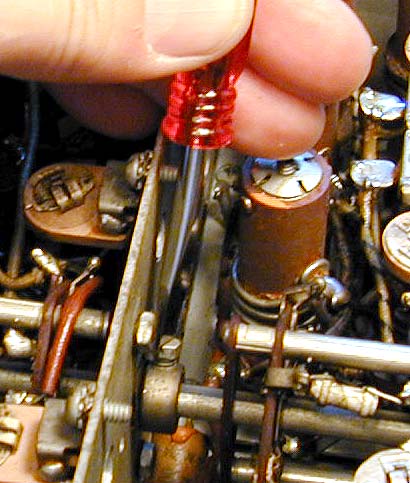
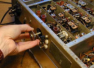
Minor disassembly is required to reach some capacitors. To replace the capacitors around the audio output tubes, you'll need to loosen a small choke and move it to one side. The choke is bolted to the side of the chassis with two screws. The next photo shows the choke hanging to one side, exposing the area underneath. (The choke looks like a small black transformer.)

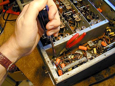
A tone control capacitor is slightly buried behind the BFO control. The next photo shows how the BFO has been loosened from the front panel to permit access to this capacitor.

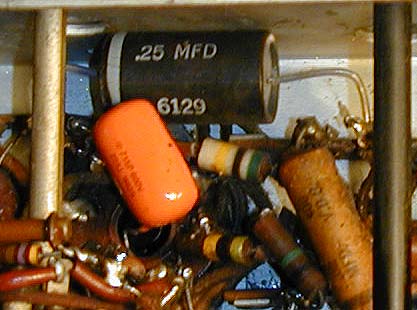
Most radios of this age have been serviced over the years, and it's amazing what you find inside some of them. The next photo shows a .25 mfd capacitor installed in a place where the schematic calls for .02 mfd. The wrong replacement was ten times the required value.

In another place, someone had installed a 27-ohm resistor in a place where there should be a 27,000-ohm resistor. The wrong replacement was only 1/1000th of the required value! Some times these little goofs are comparatively harmless, since the value of the component was not critical in the first place. In other cases, the mistake can seriously mess up your radio. As it happened, the 27-ohm resistor was installed in a real trouble spot, but we'll get to that later.
The next photo shows the radio after all of the "easy" capacitors had been replaced. Incidentally,
you may notice that I used two different types of new capacitors: small yellow ones and somewhat
larger "orange drops." There's nothing mysterious going on here. The two types are
equivalent and I simply used what I happened to have on hand. The little yellow ones are easier
to fit into small spaces, of course.
At this stage, the radio still played as well as before, although it sounded rather harsh and "too loud" except at the lowest volume levels. The AVC circuit seemed to be working in a gross sense, but perhaps there was still some tweaking left to do there.
I made a note to check the AVC levels farther down the road. First, however, I had to roll up my sleeves and delve into the dreaded RF box. In the previous view, the RF box is the squarish metal enclosure occupying the center right of the chassis.
Replacing Capacitors in the RF Box
The following section is based on a procedure documented by A.B. Bonds, a veteran boatanchor restorer who has contributed advice on a number of occasions. I have added illustrative photos and some additional notes from my own experience. Mr. Bonds' comments will appear in boldface.
There are 11 wax capacitors in the RF deck of a Hallicrafters SX-28. While it is possible to replace a few of them with hemostats and a long thin soldering iron, some are so buried that they are not even visible. There follows a description of how to open up this deck. It is not for the faint of heart. I am limiting the description to access to the RF amplifiers, since they are the most difficult to get to otherwise. The theme may be continued on to the oscillator, etc. at your own pleasure. It's a good idea to check the tuning stability of the set before you open the RF box. Any instability, especially at higher frequencies, may suggest replacing the mica oscillator capacitors while you are there.
Step 1. Remove the top of the RF/variable cap box and pull the four tubes.
As shown earlier, the RF box is the big square enclosure in the center of the upper chassis. There are a couple of styles of cover. One style, shown here, has vents. The other style has holes for ventilation. Both are held on with a few screws. Before you go any farther, get a Ziploc bag or little glass jar to hold the various screws and other small parts that you'll be removing. I tagged and labeled each set of screws with tape, to keep them separate, since there are various sizes, which are not interchangeable.
Step 2. Tag and then desolder the wires connected to the last gang of both the main tuning cap (two wires, one terminal) and the bandspread cap (3 wires, two terminals). I found the solder in this boatanchor to be very high melting point, so you will need a hot iron.
The following photo shows the upper RF deck with the tubes removed and the wires unsoldered and tagged as described above. I used small bits of labeled tape to tag the wires, which will need to be drawn down through holes in the chassis when you remove the first panel from the RF box in the under chassis.

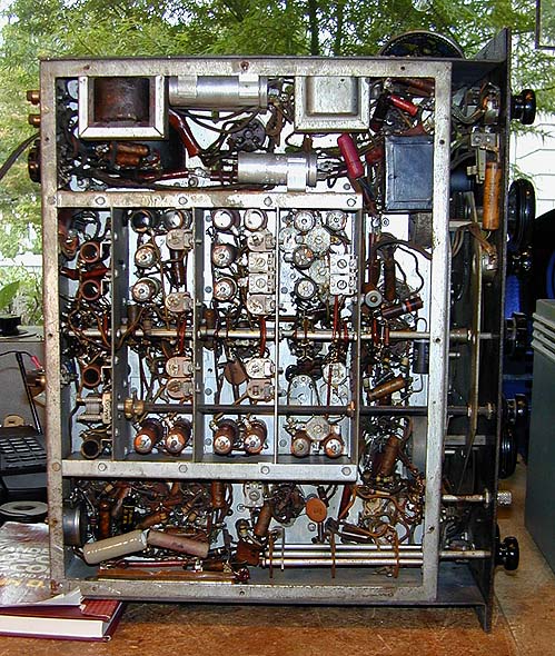
Step 3. Turn the receiver over and rest it on its top with the rear apron facing you. All descriptions of position will be with respect to this orientation. Go to your chiropractor for an adjustment.
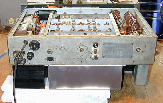
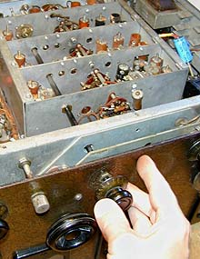
The next photo shows the receiver on its back. Before turning it over, you may want to remove the rectifier tube, which sticks up pretty high and is easy to smash if you lie the receiver down without supports. To prevent damage, I rested the receiver on three layers of stiff styrofoam board. The transformer and RF box at the rear of the chassis are strong enough to support the receiver's weight comfortably. Be careful when turning over this heavy set. I found it easiest to first tip the receiver onto the side of its front panel, then swivel it into position to place upside down on the bench.

Step 5. Use a 1/4" nut driver to remove all of the screws on the upper edges of the RF side shields. These screws hold the internal shields in place.

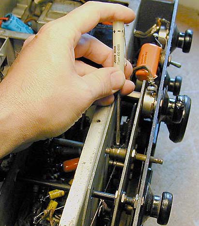
Step 6. Turn the bandswitch to band #2 (this is for access in the next step). Remove the bandswitch knob. If the shaft has any burrs from the knob setscrews, use a fine file to smooth them down. Remove the two screws holding the back of the bandswitch to the rear panel.

Step 7. Loosen the setscrews on the two small drums located on the bandswitch shaft within the RF box. The drums are located against the two rear separating walls within the RF box. Each of these drums has a tension spring, which looks like a bent washer, which you will need to catch with a needle nose pliers when the bandswitch shaft is drawn out.

Step 8. Loosen the setscrews on the dial indicator drum. This is the brass cylinder that is on the bandswitch shaft, located in the gearbox.
Note that there are two screws on the brass indicator drum, placed next to each other. One holds the dial string to the drum and the other is the setscrew holding the drum to the bandswitch shaft. On my set, frayed bits of dial string concealed the setscrew, making it hard to spot at first.
Step 9. Gently pull the bandswitch shaft out about an inch. Do not lose the little tension spring (looks like a bent washer) that is between the dial indicator drum and the front panel of the gearbox. Let the indicator drum hang on its string.
After loosening the indicator drum and moving it slightly away from the front panel, I grasped the tension spring with a needle nose pliers and held it while drawing the bandswitch shaft out far enough to free the dial indicator drum. Now you can pull the bandswitch shaft completely out from the rear, as shown below.

While the bandswitch shaft is out of the radio, be careful not to move the bandswitch wafers unnecessarily. If you accidentally twirl one of them far enough to get it back on the shaft the wrong way, you could create some truly awful misconnections!
Step 10. Loosen the setscrews on the antenna tuning shaft (at the coupler to the variable capacitor) and pull the plastic tuning shaft all the way out.

Step 11. Remove the nut that secures the grounding lug for the filament circuit from the left shield.
Step 12. Find a good Philips screwdriver. Torn-up Philips screws are impossible to remove, and the ones you have to hit next are in impossible places. Remove the four Philips screws that attach each side-shield to the chassis. The right side is easy. To remove the ones on the left side, you must unclip the filter capacitor attached to that shield and unscrew (with a 3/8" nut driver) the attachments of the shielded pair that are grounded through the two inner mounting lugs of the power transformer. By lifting the shielded pair, which is covered by brownish tubing, you can (barely) get to the Philips screw heads.
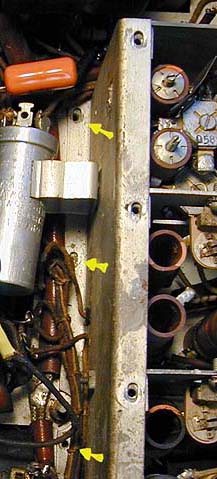
Most of these screws are concealed under strapped wire bundles that run along the bottoms of the side shields. By gently pushing the wires aside, I was able to remove all of these screws without removing any other parts. The next photo shows how I unscrewed one of the screws on the right side while a pliers held the wire bundle aside.

A long tweezers or hemostat will be very useful for retrieving screws and other small parts from tight places.

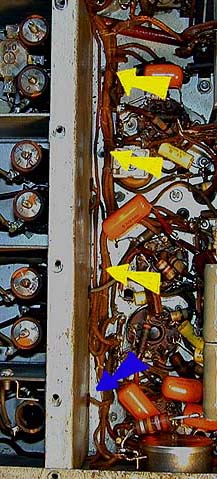
Next are two views of the left side and right side respectively, with some colored arrows pointing out most of the screws. The blue arrow in the second photo marks the wire mentioned in the next step.

Step 13. Desolder the wire going through the right shield to the rightmost coil in the rearmost compartment.
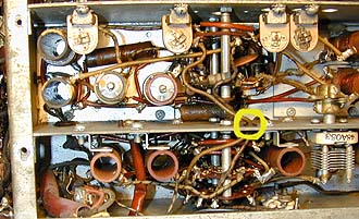
Step 14. Tag and desolder the pair of wires that go to a switch wafer and run through the top middle of the divider ("front") for the rearmost compartment.
In the next photo, these two wires are marked with a yellow circle at the point where they pass through the divider into the rearmost compartment.
Step 15. Unscrew the nuts holding the antenna input posts, thereby freeing the antenna leads internally.

You may as well remove the ground post, as well as the antenna posts, while you're at it. The ceramic insulators on the antenna posts may be broken if the mounting screws have been over tightened. One of my insulators had been cracked long ago, judging by all the dirt in the cracks, but it still was held in place by screw tension. After removal, I cleaned off the pieces and super-glued them back together. During later reassembly, I swapped the inside and outside insulators on that post, putting the never-broken insulator on the outside for better appearance.
Step 15. Remove the screw and nut holding the braid connection that runs to the rear chassis wall.

Although it wasn't evident at this stage in my restoration, this might also be a good time to loosen the nut securing the phono jack to the rear apron. This allowed me to swivel the jack to the side later on, providing just enough clearance to winkle the first divider panel out of the RF box. The phono jack is just to the left of the nut driver in the previous photo.
Step 16. Remove the Philips screws holding the dividers down. There are four for each divider. A long grabber (tweezers or hemostat) is essential to get these suckers out.
In the next photo, two of the four divider hold-down screws for the second compartment are marked with yellow arrows.

Removing a hold-down screw from the next compartment. Believe me, you're going to appreciate a good set of tweezers!

Step 17. Gently pry the sides of the RF compartment apart. Then, pull the rearmost divider toward the rear to unhook it from underneath the base plate in the next forward compartment.
On my SX-28, the sides of the RF compartment were immovable. Perhaps the rear of the chassis had been dropped during service, or that rear apron lip had simply been compressed by the weight of the receiver over several decades. Whatever the cause, I couldn't budge either side panel a bit using my hands. Gentle tapping with a thick wooden dowel and a hammer allowed me to free the side panels and slowly move them apart, far enough to release the rearmost divider.
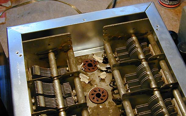
Step 18. At this point the rearmost divider can be swiveled up to the left. There are some more wires holding it in on the left side, but they do not have to be removed to get reasonable access to the first tube socket.
The next photo shows the set at this stage. With the divider swiveled upward, you can easily reach the socket of the first RF tube (V1, 6AB7). The bandswitch hole makes access a lot easier.

To reach the next compartment, however, I needed to unsolder the remaining wires holding the first divider panel. These come in through a hole in the panel. Two of them go to a bandswitch wafer and a third goes to a coil. I tagged each wire with a label and also made a little sketch to ensure correct replacement.
With those wires removed, you can gently draw them through the hole in the first divider and then remove the divider from the chassis. The next photo shows the first divider. At this stage, I had already replaced the old capacitor under the coils with a new orange drop unit. Unless you remove the divider from the chassis, you won't be able to see that capacitor, much less replace it!

Step 19. Replace all the caps and most of the resistors while you're there. I found that all three caps in the rear compartment were marginally leaky, causing the eye on my Heath cap checker to close about halfway at 150 volts. I also found about half of the resistors to be out of spec (e.g., 135k for 100k).
I agree that it's crucial to replace all of the paper capacitors in the RF box. Several of them are AVC bypass capacitors, which can affect the entire AVC system (and thus, the S-meter). Fortunately, with the first divider removed, the worst part of the job is over.
With the first divider out of the way, it didn't take long to replace the capacitors in the second compartment. The next photo shows the receiver at this stage.

There are two paper capacitors which lie smack against the dividers in the second and third compartments. Be careful to position the replacements down as far as possible, to avoid hitting the bandswitch components.
In the previous photo, look at the rightmost yellow capacitor. I left this one disconnected on one end until the divider was reinstalled, to make it easier to slip the divider back into place. Near the middle of the photo you'll see an orange drop capacitor installed right against the second divider. When I reinstalled the bandswitch, I discovered that this capacitor was too fat! When I tried to turn the bandswitch to the highest band, the setscrew for the little tension drum hit the back of the capacitor. When I replaced it with a smaller yellow cap, there was enough clearance to get the bandswitch into the highest band.
Step 20. Reassemble, then go find a cold 807. The whole process takes four or five hours if carefully done.
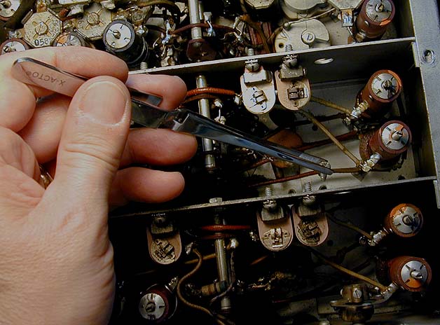
I didn't keep careful track of the time, but I suspect it took me more than four or five hours to do this job. It will depend on how fast you work, and whether you encounter any unexpected problems (broken wires, etc.). You will need a long, thin soldering pen to replace all the capacitors without removing the other dividers from the RF box. My trusty old Weller was too fat to reach into some of those crannies. At a local hobby store, I found an X-acto pen that fit the bill. The X-acto's quality is inferior to the Weller's, but I couldn't have finished this phase without it.
If you don't remove the other dividers, you won't be able to reach a number of resistors around the tube sockets. It's your call whether to do the extra unsoldering to remove those dividers. The basic procedure is as described above. Unsolder wires leading from the tuning caps down through the chassis into the RF box. Unsolder any other wires holding the divider to the chassis, then remove the divider. I was pretty tired of the RF box at this stage, so I decided to button things up and see how the radio worked.
To my delight, it worked nicely, indeed. It was a tremendous confidence builder to get all those parts and pieces back in place, after having had the radio's guts out on the workbench for a few days!
Reviving the S-Meter
With a fresh set of capacitors in place, I was ready to revisit the unresponsive S-meter. If anything, it was less responsive than before. Where before it had twitched slightly on a strong signal, now it lay on the right pin, barely moving at all.
In the course of fixing the meter, I learned a lot about the radio's AVC, ANL, and S-meter circuitry. Checking the voltages on the S-meter amplifier tube (V7, type 6B8), I quickly discovered that the plate voltage was lower than normal—only about 2 volts, rather than the 17 volts specified in the SX-28 manual or the 50 volts specified in the military SX-28A manual.
The meter circuit itself is not very complicated. One end of the meter is connected to the plate of tube V7. In parallel with the meter's terminals is a 100-ohm resistor. The other end of the meter is connected to the S-meter adjustment potentiometer, a 500-ohm unit. The adjust pot is connected to a 27K-ohm dropping resistor which in turn connects to the radio's 280-volt B+ line.
When I bought the radio, someone had installed a 27-ohm resistor where there should be a 27K resistor. Installing a resistor of the correct type did not correct the problem, however.
As an experiment, I tried substituting resistors of lower values for the dropping resistor. This attempted fudge didn't work. With a lower-value resistor in place, the voltage at the plate of V7 did not rise as expected. When I put in resistors of lower and lower values, they tended to overheat and burn up. Clearly, there was something else at fault besides this resistor—perhaps a resistance leak somewhere along the line.
Since the meter is dependent on the AVC working correctly, I spent considerable time checking the dual AVC system, testing components and replacing marginal resistors as well as a few mica capacitors.
AVC is also dependent on the receiver being correctly aligned, so I hauled out my signal generator, frequency counter, and multimeter, and went through the complex alignment process.
The SX-28 alignment procedure includes steps for aligning the ANL (automatic noise limiter) and AVC. During the AVC step, I was unable to find a peak anywhere in the adjustment range for transformer T6. This transformer feeds signal from the plate to the diodes of tube V8 (type 6B8), the AVC amplifier.
Since I had already replaced almost every other component in the neighborhood of tube V8, it made sense to test that transformer. With an ohmmeter, I confirmed that the transformer windings had continuity, which is always good news. That left the two mica capacitors inside the housing as the only remaining suspects.
Before pulling the transformer, however, I did a static test on it using a signal generator and oscilloscope. Fellow SX-28 owner John (W3JN), who incidentally supplied lots of other good advice to help diagnose this problem, suggested this test:
Phil - yes, there *is* a way. Connect your signal
generator to the primary with the hot lead thru
a 10K or so resistor so that the low impedance of
the sig gen doesn't wreck the Q of the transformer.
Crank up the sig gen as high as it'll go. Then
connect a scope to the secondary (this is all with
the power off, BTW), set it for max sensitivity.
Rock the sig gen thru the freq range (say 400 to
500 KHz) and observe the scope to see where the
peak or dip is. This will give the resonant
frequency of the transformer. If it's way off
455 KHz then the cap(s) have changed value and
need to be replaced. BTW this should be in situ
with the tube in its socket, etc., just power off.
The resonant freq wil change a tad with the power
on most likely but if the caps have drifted way
off this is one way to tell.

73 John
The oscilloscope test also indicated that the transformer wasn't peaking anywhere in its range, so I unsoldered the transformer connections and removed it. The next photo shows T6, ready for service.

Sure enough, one of the capacitors (C112) was far off its specified value. The other capacitor was still within about 5% of spec, so I left it in place. After reinstalling the transformer, I got a nice peak during the AVC alignment.
It was satisfying to fix a bum transformer so easily, but the meter behaved no better than before. To eliminate the meter itself from the equation, I tried two tests. The simplest test was to disconnect the Hallicrafters meter and temporarily substitute a similar DC milliammeter in its place. The other meter, a new one that I happened to have lying around, behaved exactly like the old one.
That suggested that the problem was not only in the meter, but it didn't necessarily prove that the meter was good. More than once, I have found two problems at play where I initially suspected only one. Walt Heskes, another long-suffering and generous technical adviser, suggested the following test for the meter.
You most certainly can test your S-meter. Here's
one way to do it safely: The meter is measuring
small amounts of current in the AVC circuit.
Therefore, the max deflection shouldn't take more
than  a few milliamperes. So, if you disconnect
the leads of the meter from the circuit and connect
it in series with a resistor and a DC supply, such
as a battery, you should simulate the same sort
of deflection you should get at runtime.

Now, here are some values you can try:

If E = i*r, then if E = 6 VDC and we want a 1 mil
deflection, R should be E/i or 6/.001 = 6000 ohms.
So, a 6000 ohm resistor in series with the meter
and a 6 volt supply should gently move the meter.
As a double check, I first tried this test on a new meter, which I had earlier used as a substitute. Then I tried it on the Hallicrafters meter. Both meters behaved identically, and exactly as Walt had predicted.
I knew that the meter was good. I knew that transformer T6 and countless other components on related circuits were good (since I had replaced and double-checked them). I knew that the relevant tubes were good because I had not only tested them but also tried substituting other known-good tubes in their places. I knew that the voltage at the plate of tube V7 (and hence at the S-meter) was too low to make the meter function. But I didn't know why!
While working on this set using the "civilian" SX-28 manual, I had ordered a copy of the military SX-28A service manual, and it finally arrived just in time for this phase of the investigation. The civilian SX-28 documentation runs to 30-odd pages, but the military version is vastly more detailed.
If you need to overhaul an SX-28 or SX-28A, I strongly recommend that you get the military manual. It includes an extensive theory section describing the operation all circuits, and invaluable reference info such as a chart of resistance values for every pin of every tube. (To align the RF and oscillator sections, however, you must have the correct manual for your radio—SX-28 or SX-28A—since the location of the various trimmers and coils differs between the models.)
A resistance chart can be invaluable to pinpoint specific problems. The process is tedious. You pull all the tubes out of the radio, fire up your ohmmeter, lay out your notebook, and test the resistance found at every pin of every tube in the radio. The SX-28 has fourteen octal tubes and one four-pin rectifier, so a full resistance check amounts to 116 measurements. For this kind of work, I make a second copy of the manual page containing the resistance chart. The original page serves as my reference, and on the copy I write in the actual measurements for the radio under service.
Not surprisingly, most resistances in the radio were within normal (i.e., plus-or-minus 20%) specifications. The glaring exception was found on tube V7. That day I got the following email from John.
You have a short somewhere between the meter and the
plate of V7. Check resistance from the meter terminals
to ground. Try disconnecting the wires to the pot,
see if the short goes away. Maybe the problem is in
the pot.

Keep your chin up, you've almost got it licked!

73 John
Within a few hours, I got a similar response from adviser Walt Heskes.
There's simply got to be something awry in the AVC.
When you run through all of the modes, you get the same
S-meter response? What kind of response do you get
when you fidget with R29, the zero adjustment?
Suppose you bypass R29? What happens on strong signals?

Is that pot doing its job?

Walt
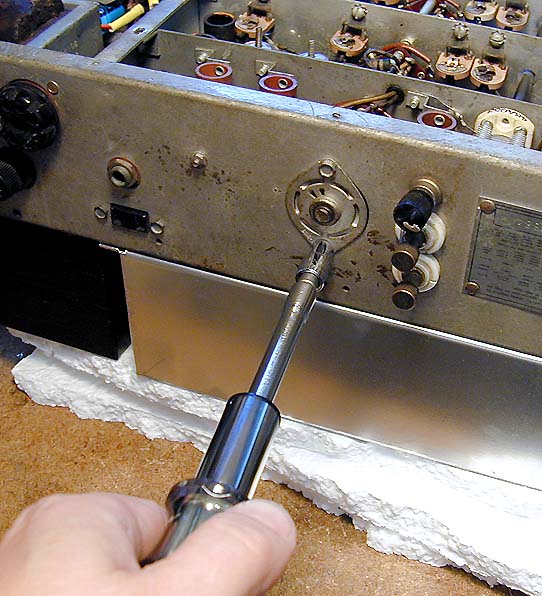
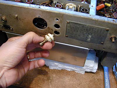
The votes were unanimous, so I pulled the S-meter adjustment potentiometer and quickly found that its center terminal was leaking to the case. Not a dead short, but certainly sufficient to leak enough voltage to prevent the plate of V7 from receiving its share. I temporarily connected a replacement potentiometer and was thrilled to see the S-meter come back to life. Problem solved!
That weekend happened to be the occasion of the NWVRS swap meet in Portland. I found a number of useful parts at that meet, including a good potentiometer to replace the bad old one. The new pot's shaft was longer than needed, but a few strokes of the hacksaw cured that. After rounding off the end a bit, you could hardly tell the new unit from the old. The next photo shows old and new pots together.

With the S-meter working and the AVC voltage strong on both lines, all that remained was to do the alignment one last time. If you have never aligned an SX-28 before, I have just one piece of advice: take your time and follow the instructions exactly!
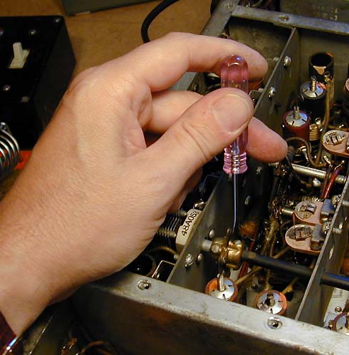
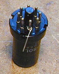
Here's a little trick that can help in the alignment. To align the IF section, you need to connect the hot lead of the signal generator to pin 8 of the mixer tube (V3, type 6SA7). The underside of this tube is buried deep within the RF box under the chassis, almost impossible to reach. To reach it from above, simply pull tube V3, bend a little piece of wire around pin 8, with enough extra length to stick up at an angle when you replace the tube. You can clip your signal generator lead to the little wire during the alignment. The next photo shows what I'm talking about.

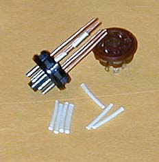
After thinking about it for a while, I came up with a better solution—a tube extender that gives easy access to any of the pins. I built it from a standard eight-pin socket and base, connecting the two parts with 14-gauge solid copper wire.
The next photo shows the extender under construction and finished.


The 14-gauge wire is exactly the right diameter to fit snugly inside each pin of the base. This wire is heavy enough to make the whole assembly strong and rigid.
I put two pieces of insulation on each leg of the extender, cutting the insulators short enough to leave a little bare space on each connector. The idea is that to connect a test lead to any pin, you slide up the upper piece of insulation. The insulation on adjoining connectors remains down, preventing short circuits. The next photo shows the extender in action.
The extender is plugged into the tube socket, and then you plug the tube into the extender. An extender like this would also be very useful for testing voltages without removing the chassis from the cabinet. For tubes with different numbers of pins, you will need to substitute the correct sockets and bases, of course. A couple of years after writing this article, I found a set of factory tube extenders, which you can view in my Philco Predicta article.
Cosmetic Restoration
With the electronics in good working trim, it was time to turn to cosmetics. The front panel looked like it had been stripped to bare metal and covered with dark varnish. The only cure there would be to repaint it in the original color and restore the white and red lettering using lacquer sticks. Since the lettering, pinstripes, and leather-like texture on the front panel is stamped into the metal, it's comparatively easy to redo.
The paint on my cabinet was quite good, so after removing the extra handles and filling those holes, it would be a small job to touch up the hole repair and shine up the aluminum on the side trim panels.
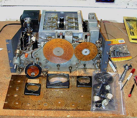
The next photo shows the front panel removed from the receiver. This involves removing all the knobs, unscrewing the mounting nuts from the phone jack and toggle switches, disconnecting and removing the S-meter, and carefully taking off the dial covers and their glasses. To prevent loss, most of the mounting nuts and assorted screws have been reattached to the places they came from. The knobs are carefully squirreled away in a big Ziploc bag for later cleaning.
With the front panel off, I had great access for cleaning and lubricating all of the tuning gears and bandswitch pointer machinery. Before reinstalling the panel, I would also restring the dial cords, which were functional but frayed.
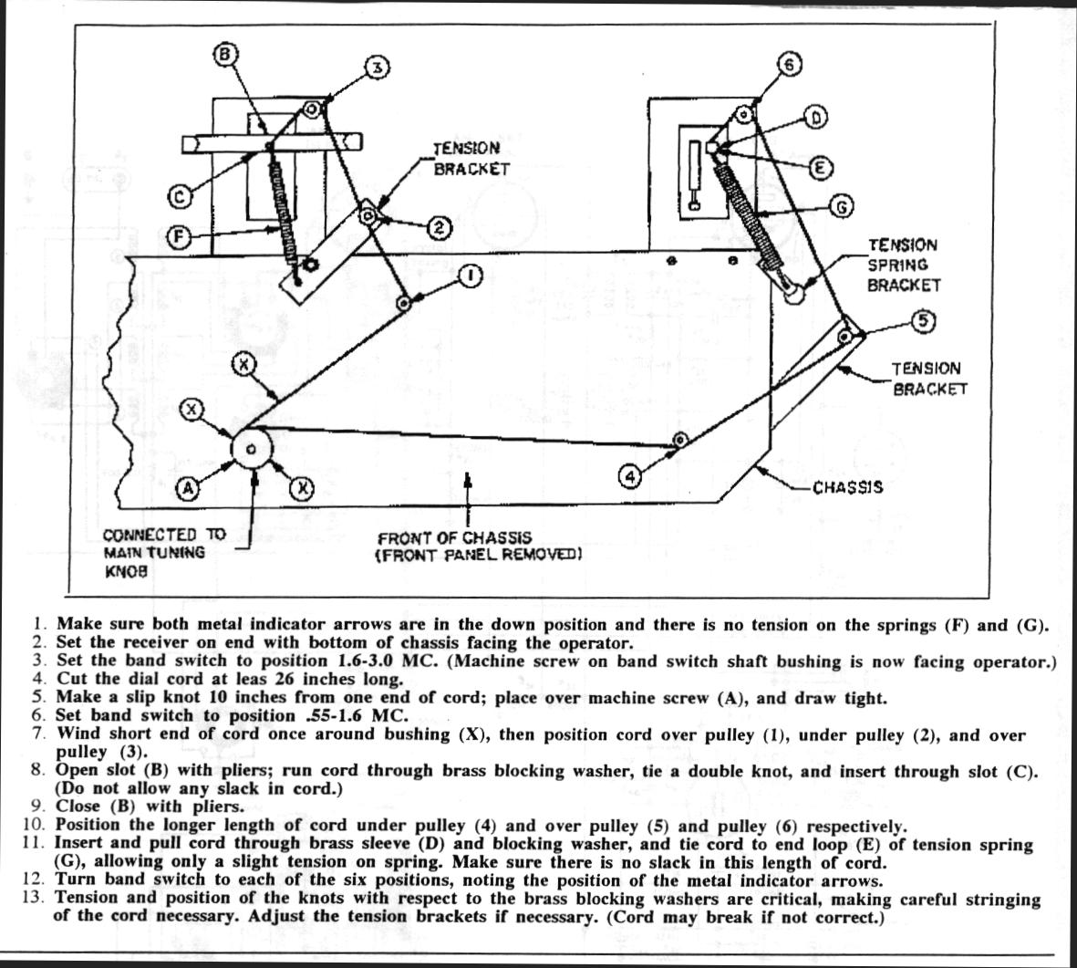
The SX-28 has a complicated dial stringing arrangement, which not only turns the tuning dials but also moves
the band pointers up and down behind the main tuning dial and bandspread dial. Below is a
diagram from the military SX-28A manual.

Doug Moore has written an extraordinary article detailing the SX-28's tuning gearbox and stringing mechanism.
Check out Secrets of the
SX-28 Gearbox for his authoritative discussion.
Repainting the Front Panel
The next step was to strip the old dark gunk from the panel. When I removed the dial covers, the gunk underneath looked suspiciously orange, almost like old shellac. I ran a sink full of hot soapy water and let the panel soak for a while, then started gently scrubbing. Sure enough, the finish was shellac, and it came off easily.
Lots of old paint remained in the stamped lettering and wrinkle texture, however. After drying the panel, I lay it down on a thick pad of newspapers and applied a thick coating of Citri-Strip stripper. A couple of hours later, the paint had loosened sufficiently to come off easily with a small brass brush.
Here is our patient at this stage of the proceedings. Looks messy, but things will get better soon!

All of the SX-28 panels that I've seen are colored a very dark gray. They are not quite black, but not as light as the dark bluish gray used on the S-20R cabinet. The closest match that I could find at any local paint store was plain old black enamel. To judge what it would look like, I applied a coat of primer to the back of the panel, followed by a coat of the black enamel.
The result was too dark, in my opinion. To double check, I buffed off a spot on the back of the panel to expose the original color. Sure enough, the original was not pure black. I took the panel to an auto body supply store and had them do a color match on that spot and make me a spray can of that color. Then I applied primer to the front of the panel, followed by three coats of the colored enamel.
To restore the lettering, I used red and white lacquer sticks from Antique Electronic Supply. Using these is simple in theory. You rub the paint into the recessed lettering, and then wipe the excess away from the surrounding area.
Easier said than done! It took several tries to get this right. At first, I rubbed paint into the lettering and then immediately tried to remove the excess. A common technique, I had heard, was to drag a paper towel moistened with paint thinner gently across the letters. I also tried using a cloth wrapped around a small, flat object. No matter what I tried, the paint tended to come back up out of the letters. It was also difficult to avoid getting a lot of color into the "wrinkles" surrounding the letters.
I asked for advice from the rec.antiques.radio+phono newsgroup and got a lot of information about different kinds of lacquer sticks (hard, medium, soft) and how to use them. The harder lacquer sticks need to be melted over a flame or softened by kneading. It may help to heat the panel, and so on. I did some calling around the area and was not able to locate any different kinds of lacquer stick in the colors that I needed, so I was faced with learning how to use what I had. The answer finally came from Walt Novinger:
If you bought the lacquer sticks from Antique
Electronics Supply (we have used them on several
SX-28 panels), go to an autobody store and get
a small hard-plastic squeegee that's used with
Bondo. Rub the lacquer stick across the letters,
wait a few minutes, and strike it off level with
the surface using the squeegee. Works like a charm!
As more than one person had suggested, letting the lacquer dry was essential. Impatient, and worried about not being able to remove excess from the wrinkles, I had been nervous about letting the lacquer sit too long. Following Walt's advice, I bought a plastic bondo scraper at an auto parts store and cut it to a convenient size using a jackknife.
When I let the lacquer set up for about 10 minutes, the excess came off and the letters were nicely formed. The next photo shows this process.

After scraping most of the excess from every set of letters, I went back with Q-tips moistened in turpentine and carefully cleaned up as well as possible, without getting solvent into the letters themselves. This painstaking process took much longer than getting the paint into the letters.
At this stage, I had letters that looked very nice but which were surrounded by small hazy areas of white residue. I put the panel away to dry overnight, putting it under a little bit of heat from a lamp to make sure the lettering dried well. If you are doing this in a cool or humid place, you may need to allow more drying time for the lettering.
The next day I gently polished away the haze, using Novus Plastic Polish #2 (my favorite all-purpose polish). The Novus removed the haze and gave a little extra protection to the entire panel. The next photo shows the restored panel with the dial covers back in place.

(2003 Update: Some time after finishing the panel, I noticed that I had made a minor mistake. The phrase "Model SX-28" in the center of the dial should be colored white, not red. The only red portion is the phrase "Super SKYRIDER" with its flanking chevrons.)
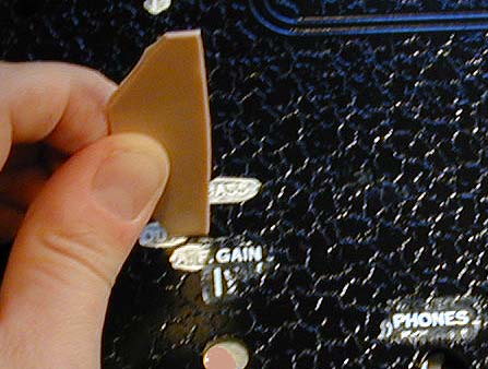
A note about the "hairline" markers in the tuning dials. They are thin pieces of springy steel, which are friction fit into slots at the top and bottom of the dial openings. I had removed them while restoring the panel, cleaned and repainted them, and reinstalled them after the panel was ready for prime time. Use care when removing and installing these thin markers. If they are rusted in place, it can be tough to break them loose. Mine slipped out to the right, as you are facing the panel.
Putting It All Together
At long last, I was ready to put the SX-28 back together. During the panel phase of the project, I had carefully cleaned all of the knobs, using a warm-water soak to remove the orange shellac that had been sprayed on them.
Note that the numbers and markings on the knobs
are painted on. Don't scrub them too hard, or you'll remove
the markings.
Digging into the Ziploc bags, I laid out all the knobs and mounting hardware needed to put the panel back on.
The SX-28 panel is secured to the chassis with six screws. Two on each side hold it to the chassis side panels. There are two additional, smaller, screws near the center, between the tuning knobs. These screws go into metal spacers projecting from the front of the chassis.
The previous owner had used sheet-metal screws to hold the panel onto the chassis, damaging the screw threads. I was told that 10/24 was the correct screw size, so I bought several of that size with hex key heads. If you need to exert extra force, a hex head is much less likely to strip than a slotted or Philips head. None of the screws would go in from the front without further damaging the threads. I put a drop of oil on each screw and carefully backed it in from the rear of the chassis hole. Running the screw in and out a couple of times repaired the threads.
To reinstall the front panel, slide the chassis so that its front sticks out slightly over your workbench. Holding the bottom of the front panel with one hand, insert the controls and switches with your other hand, working from the bottom up. Note that three of the controls—ANL, antenna trimmer, and the AVC/BFO switch—use little metal collars which are secured with nuts from the back of the panel. Slip these three nuts over the control shafts before inserting them in the panel.
With everything loosely in place, I lightly installed a couple of panel mounting screws to support the panel. Then I was able to secure all of the mounting hardware, using two hands.
Before you tighten everything down, check the clearance between the tuning dials and the mounting screws for the dial covers. A previous owner had used the wrong kind of screws to mount the covers; the screw heads stuck out far enough to scratch the dials when the panel was fully tightened. I didn't notice this until I had put everything in place, which meant that I had to disassemble everything, replace the round-head screws with flat-head screws, and then repeat the assembly process.
The "gothic" cabinet only required a little hole patching, after I removed the chrome kitchen cabinet handles from the top, and touch-up painting.
Then it was time to install the chassis. The easiest way to do this is on a deep workbench. Put the chassis on the front edge of the bench, sticking out slightly over the edge. Put the cabinet behind it. Slip the power cord through the cabinet, tilt up the back of the receiver, and gently slide it back in.
Final thoughts
The final photos show the completed receiver in action, with its matching PM-23 speaker. To be honest, I don't like the color of the cabinet at all. It's a sort of greasy greenish light gray, not a good match for the panel color at all (or for the PM-23 speaker cabinet, for that matter). If I knew I was going to keep this set for the rest of my life, I'd probably say the heck with authenticity and repaint the cabinet and speaker to match the front panel. Then if I chrome-plated the side trim pieces on the cabinet, I could call it my Harley-Davidson SX-28!

I hope that you've found this SX-28 page helpful. If you'd like to share your SX-28 experiences, or you have some additional restoration tips, just send me some email
Out with the new, in with the old!
About one week after I finished restoring my first SX-28, I ran across a second one, and just couldn't resist. Here's a shot of the two together.

The new arrival was filthy and covered with thick layers of smelly tobacco grime. But all the pieces were in the right places, and it performed reasonably well on all bands. At the time of this update (four years later!), I have completed its restoration,
but haven't finished the article yet.
I own around a dozen Hallicrafters receivers. To read about others, including model SX-42 and the legendary SX-88, visit our Communications gallery.
Happy listening!
Phil
|