Philco Model 37-61 Tombstone Radio (1937)


My Dad found this classic Philco tombstone set for me in Minnesota, at the estate
sale of a former radio repairman.
Although the radio looked pretty rough at first, it proved to be an easy restoration
and a good value, given the $35 purchase price.
Shipping this set from Minnesota to Washington required careful packing on
my Dad's part. As with many 1930s radios,
the cabinet's glue joints had loosened in several places. The structural
joints were almost completely unglued, and the veneer was seriously delaminated
on the sides and bottom of the case. The top veneer was delaminated to a lesser extent.
If I had to guess, I'd say the radio spent some years in a garage, where it was
exposed to Midwestern extremes of temperature and humidity, a combination
that's very hard on old glued joints.
Repairing a cabinet in this condition is not particularly difficult. You simply
reglue the loose parts. But if you
need to ship it, you absolutely must remove the chassis from the cabinet.
Even if the cabinet is not damaged, the heavy chassis may punch through the bottom
of the cabinet, causing all kinds of havoc during transit. My Dad shipped the cabinet
and chassis in separate boxes, double-boxing each piece.
Description
Tombstone cabinets were very popular during the 1930s. This 1937 radio is a typical example.
Other tombstones in my collection include a 1934 GE S-22X, a
1938 Stewart-Warner 91-531, and a 1937 Zenith
6-J-230.
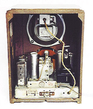
Printed on the tuning dial are the names of many cities, representing shortwave stations of the time.
As on my Philco Model 60 cathedral set, the dial
is made of orange plastic and it revolves against a stationary pointer. Instead of a dark metal
pointer, however, this radio has a lighted "glowing beam indicator," a light vertical stripe indicating
the tuning point. Behind the dial is a second plastic sheet with a thin vertical
slot. Light shines through the slot, creating the "glowing beam" stripe. This effect is
visible if you look closely at the front view, which
was taken with the radio turned on.
The radio uses four knobs. The topmost tuning knob has two parts,
one for fast tuning and the other for fine tuning. My radio is missing the
outer fast-tuning knob, but the fine tuner works just fine unless you're
in a dreadful hurry. Perhaps one day I'll find the missing knob in a box
of spare parts at a swap meet.
Three knobs form a row at the bottom. The leftmost knob
turns on the power and switches between normal and bass tone. The center
knob switches between standard broadcast and shortwave reception. The
right knob is the volume control.
Electronically, this set is similar to my Philco Model 60.
Here is the description from the Riders technical sheet:
Model 37-61 is a 5 tube superheterodyne receiver for operation on alternating current
and has two tuning ranges, covering standard broadcast and short wave reception. It also
uses the new Philco High Efficiency self-centering glass tubes.
The circuit includes the Philco Foreign Tuning System—controlled by the range
switch—providing maximum sensitivity and noise reduction when used with the
new Philco High-Efficiency Aerial, supplied with the receiver. This receiver
will be supplied in two model cabinets, type B and F.
The five tubes are: 5Y4G rectifier, 6A8G detector/oscillator, 6K7G IF amplifier,
6Q7G 2nd detector/1st audio amplifier, and 6F6G audio output.
The 37-61 chassis was offered in cathedral and console cabinets, as well as the tombstone
cabinet shown here.
Cabinet Restoration
This cabinet stands about 16 inches high and 12 inches wide, an
average size for a tombstone radio.
The side columns are solid wood and the top and sides are covered
with veneer. Although the front panel looks like fine, patterned
veneer, it actually has a wood-patterned photo decal glued over a cheaper wood
panel. This type of "photo-finish" cabinet enjoyed a brief vogue in the 1930s,
presumably for cost-saving reasons.
A damaged photo-finish decal is not easy to restore. Fortunately, mine had suffered
only a few tiny scratches around the edges, which were easy to touch up
with dark walnut stain and a fine artist brush. I am not aware of any source
for replacement decals. If you have a photo-finished set with more extensive damage,
the best solution is to repaint the scratched areas as best you can, using
dark brown colors and fine brushes.
Because the cabinet had so much separation and delamination,
it was impractical to glue everything at once. I did the job in phases,
letting each glue job cure overnight before proceeding.
The first step was to glue the separated bottom panel back onto the slots in
the front and side panels. I did this with the cabinet lying on its face,
using long woodworker's clamps to compress the sides and a pile of heavy books
to weight the front joint.
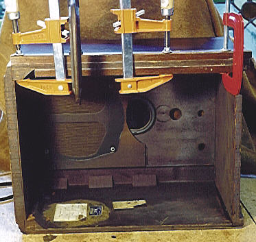
The next step, shown in the following photo, was
to glue the corner joints at the top rear of the cabinet and the separated veneer
on the rear of the cabinet top. (Click the thumbnail photo to see
a larger view.)
Here, the long clamps were used to hold the corner joints and smaller
clamps were used to hold the separated veneer on top. Small pieces of wood
were used between the second pair of clamps to spread the pressure and
avoid damaging the thin veneer.
The side panels were delaminated to a depth of about one inch along the
back and bottom of the cabinet. The next photo
shows one side being glued. All four clamps were used on this side. I padded
the clamps with pieces of scrap wood cut to the proper length to fit along
both sides of the panel.
As you can see in the photo, the original paper labels are still present
inside the cabinet. The grille cloth, still in fine condition, is mounted
on a piece of cardboard with cutouts for the speaker openings.
After gluing the right side, I repeated the process on the opposite side of the cabinet.
Using the right amount of glue is important when repairing loose veneer.
Use an index card or thin knife blade to work the glue well into the
space between the pieces, then carefully wipe all excess from the joint after
clamping it. Avoid applying too much pressure, which
may squeeze all the glue from the joint and leave you back where you started.
I like to see just a little bit of glue peek out of the joint when it is
well clamped, but not so much that it makes a mess.
The type of glue is not critical. Any good-quality woodworker's glue should
hold the cabinet together for many years to come. I have even used ordinary
Elmer's brand household glue.
The last bit of gluing involved the top veneer, which was separated along
the front and one side. Clamping the top would require at least three long
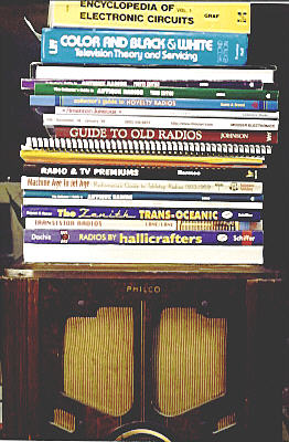
clamps, but I have only two of that size, so I substituted an armful of
books from my radio library. I put a sheet of wax paper between the cabinet
and the bottommost book to prevent any stray glue dabs from gluing
the book to the radio.
Once the cabinet was structurally solid, I restored the finish. The veneer had the usual
assortment of small scratches and nicks, which I concealed with a thin application
of dark stain. After letting the stain set for just a moment, I wiped the whole
cabinet with a clean cloth. This treatment left stain in the scratches but
didn't darken the rest of the cabinet too much.
As mentioned earlier, the few tiny scratches in the front panel were
concealed with a fine brush dipped in dark stain. I let the cabinet
dry overnight, then sprayed on a coat of clear lacquer, completing
the refinishing job.
Another method of restoring a not-too-worn lacquer finish is to respread
it using lacquer thinner and a retardant. I didn't happen to have the
right stuff on hand, so I used stain instead. I doubt that anyone could
tell the difference by looking, but if you're a stickler for authenticity,
you may prefer to respread the old finish rather than apply new stain.
(Don't use any refinisher on a photo-finish decal, of course.)
In any case, a fresh coat of clear lacquer is a nice way to complete
the job. If the final coat looks too shiny, buff it lightly with very fine
(#0000) steel wool.
Electronic Restoration
Restoring the electronics involved no special difficulties and required only a few hours.
The first step, as always, was to clean the chassis from head to toe.
This is an average-quality 1930s radio, so I made the
chassis clean and serviceable, but didn't go to extreme lengths to make
it shiny or beautiful. As part of the cleaning, I squirted DeOxit
electronic cleaner inside all of the controls to remove gunk and corrosion.
In this radio, the 5Y4G power rectifier tube plugs into the top
of the power transformer. In the interior view, shown below, the transformer
and rectifier tube are visible to the right. The tube stands above the
black transformer, just to the right of the twisted speaker cable.
Piggybacking the rectifer atop the transformer saves a bit of lateral
space in the chassis layout, which is useful in a vertical tombstone
design. It also puts the tube in a vulnerable exposed position. If
you work on a radio with this arrangement,
avoid turning the chassis upside down or accidentally knocking
the tube with your elbow!
The tuner portion of the radio is built on a subchassis
that is mounted in the center of the main chassis with
insulating washers. In the chassis photo above, the subchassis
looks like a shallow box in the middle of the main chassis,
containing the tuning capacitor and a tall can capacitor.
The dial lamp is clipped to the top of the tuning capacitor.
As found, the radio performed decently on both bands. That's not common for radios of
this vintage, but this set was a special case. My Dad purchased it from the estate
of a retired repairman, and evidently it had been repaired but never
picked up by the owner.
Inside the case is the serviceman's repair
receipt, showing that he replaced three filter capacitors in the power supply
and one other capacitor. The total cost of the repair was $28.13, with
an $11.80 labor charge—quite a bargain by today's standards! The receipt
is undated, but I'm guessing the work was done in the late 1960s or early 1970s.
The original "wet" type filter capacitors were disconnected but left in place,
so the chassis looks perfectly authentic from above.
Since the work was professional and the replacement capacitors still test within
normal limits, I left them alone.
Like my Philco Model 60, this set also uses a couple
of Philco's unique "bakelite block" capacitors. Those capacitors tested
within the specified ranges, so I decided to leave them in place for
authenticity's sake. You can read a little more about that type of
capacitor in the Model 60's page.
Even though the radio played fairly well, I went on to replace the remaining paper
capacitors as a preventive against future problems. I also replaced a couple of resistors
in the audio output circuit. Like most metal-cased output tubes, the 6F6G tube
runs pretty hot. When I checked the resistors in that circuit, they had drifted
upward in value quite a bit. After replacing them, the output tube
still runs hot, but now its operating voltages are normal and I can play the
radio without worrying about it going up in flames.
At that point, the radio performed well on shortwave as well as standard broadcast, so
I put it back together and deemed the restoration complete. It performs like a new
1937 radio, and I love the warm orange glow from the dial.
|