Hallicrafters Model T-67 Television (1948)


This lovely 10-inch set was my second Hallicrafters television project.
Although it's the same age as my Hallicrafters 505,
it represents a definite step up in quality. The T-67 also was easier to restore.
Description
The Hallicrafters T-67 is typical of "doghouse" shaped 10-inch televisions of the late 1940s and
early 1950s. Designed for a tabletop or low stand, it measures about 18 by 16 by 20 inches deep.
It's heavy for its size, thanks to the transformer type power supply and dual
chassis.
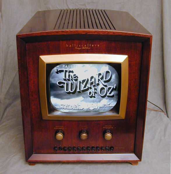
The first photo shows the restored television.
Priced at $279.50, this TV cost $80 more than the inexpensive model 505. The wooden cabinet
has mahogany veneer. Lettered in gold script over the screen are the words Carnegie Hall Edition.
Like the model 505, this set uses a row of pushbuttons
for tuning. Unlike the early 505s and T-54s, however, it does not feature the obsolete channel 1. The rightmost
"button" in the bottom row is a rotary fine tuning control.
From left to right, the three large knobs above the
tuning buttons control horizontal/vertical, power/contrast, and brightness/volume.
It's unusual to have a power knob that also controls contrast, rather than volume,
which has become the modern standard.
In this respect, the T-67 is a little like my Sparton 1271
and Dominion Electrohome console radios, which pair the power
switch with a tone control rather than volume.
Cosmetic Restoration
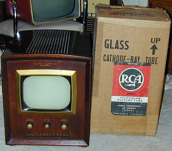
I bought this set at a local shop for $125 and the price included a spare unused picture tube.
It was a one-owner set purchased from a local estate.
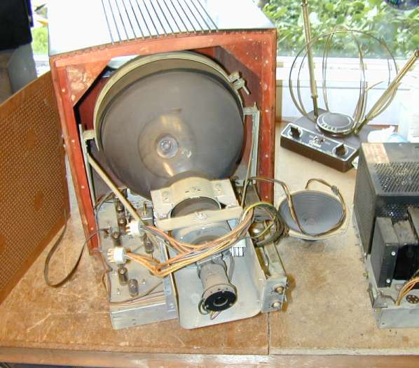
Here's the TV sitting in my study on the day I brought it home. The cabinet
was in fine shape except for a few little scratches and normal wear around the knobs.
The gold-colored bezel surrounding the screen is made of plastic. The thick safety cover
is made like an auto window with plastic laminated between glass layers.
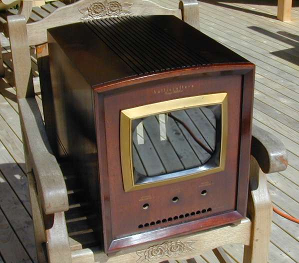
The next photo shows the cabinet after I touched up the finish. I
gave it a light wipe with mahogany stain to darken the scratches and then briskly
rubbed off the excess. Oil-based stain can take days to dry in our humid climate, so I
added a little lacquer thinner to promote drying.
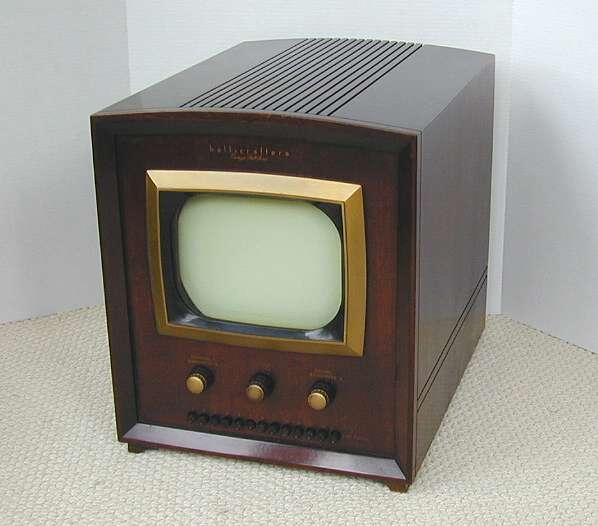
Here's an indoor shot of the finished cabinet with chassis installed.
T-67 Electronic Design
The Hallicrafters T-67 is well designed, with intercarrier audio, DC
restoration, and automatic gain control (AGC). These features provide
improved audio and video, as well as easier tuning, and they were not
present in all 1940s TVs. Hallicrafters didn't enjoy great commercial
success as a TV maker, but the T-67 compares well to my
best 10-inch performers, the DuMont RA-103 and
RCA 630TS.
Hallicrafters used this chassis in four different models from 1947-1949.
The T-61 had a black bakelite tabletop cabinet with the same profile.
Model T-64 came in a tabletop or console wooden cabinet and gave you a choice of 10-inch
or 12-inch screen, while model T-69 offered a 15-inch screen in a console wooden cabinet.
The T-67 uses 23 tubes, including the 10BP4 picture tube:
| Tube |
Type |
Function |
| V1 |
6AG5 |
RF amplifier |
| V2 |
6AG5 |
Mixer |
| V3 |
6C4 |
Oscillator |
| V4 |
6AU6 |
1st video IF amp |
| V5 |
6AU6 |
2nd video IF amp |
| V6 |
6AU6 |
3rd video IF amp |
| V7 |
6AU6 |
4th video IF amp |
| V8 |
6AL5 |
Video detector |
| V9 |
6AU6 |
1st video amplifier |
| V10 |
6AQ5 |
2nd video amplifier |
| V11 |
12AU7 |
Sync sep./DC rest. |
| V12 |
6AL5 |
Sync. discriminator |
| V13 |
6SN7GT |
Horizontal oscillator |
| V14 |
6SN7GT |
Vertical oscillator/amp. |
| V15 |
6AU6 |
Audio IF amplifier |
| V16 |
6AL5 |
FM detector |
| V17 |
6AU6 |
Audio amplifier |
| V18 |
6K6GT |
Audio output |
| V19 |
10BP4 |
Kinescope |
| V20 |
6BG6G |
Horizontal amplifier |
| V21 |
1B3GT |
High-voltage rectifier |
| V22 |
5V4G |
Rectifier scanning |
| V23 |
5U4G |
Low-voltage Rectifier |
You can download the complete Sams service manual (set 65, folder 7) from the
Early Television Foundation
archive.
If I had to fault any part of the T-67 design, it would be the pushbutton channel switches.
They have lots of contacts, which may get corroded or dirty, and lots of moving parts, which
may wear out, need lubrication, or get bent out of alignment.
Mine are in good shape, fortunately, but I wonder how well these held up under heavy use.
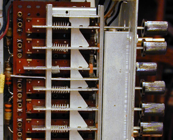
Here's a close view of the switch assembly. Channel 4 (third from the end) is
selected—pushed in and locked. A vertical rail with notches catches the
selected switch slide and locks it. Pushing in any other button
releases the previous button and then locks the selected one.

The mechanism is ingenious, but most of the contacts are inaccessible
for cleaning unless you use the sloppy method of spraying cleaner over
the whole switch and working it repeatedly.
Another weak point is the little tan rubber cushion that keeps each slide from slamming
the frame too hard when released. This cushion is clearly visible on
the depressed Channel 4 slide. Looking down a little farther, you can see that
the cushion is missing from Channel 6. Like many sixty-year old rubber
parts, it dried up and fell to pieces.
Pushbutton tuning never became very popular. By the mid-1950s,
many better-quality TVs like my RCA CT-100
used turret tuners, which are robust and easier to maintain. Turret types are
also more expensive, of course.
Electronic Restoration
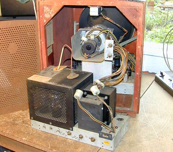
This television has two chassis. The smaller rear chassis holds the power supplies and
sweep circuitry and the larger front chassis holds the tuner and audio sections.
The two chassis are removed in steps. First, you disconnect four inter-chassis cables
and the picture tube anode lead, remove the mounting screws, and slide the rear chassis back.
Before removing the front chassis, you must unscrew the speaker from the top of the cabinet
and unplug its cable from the chassis. Be careful not to spear the speaker cone on the mounting
screws! Then you can slide the chassis partway out and unplug the speaker cable from its front.

Once the speaker is free, it's easier to remove the chassis completely.
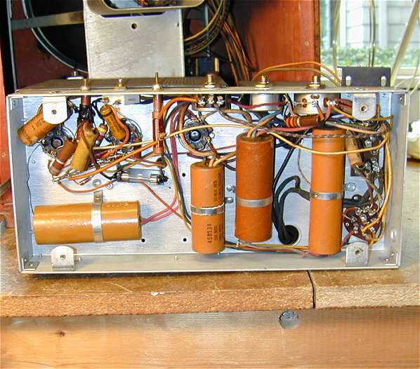
After cleaning the switches and controls and tube pins with DeOxit,
I replaced the capacitors in the power/sweep chassis.
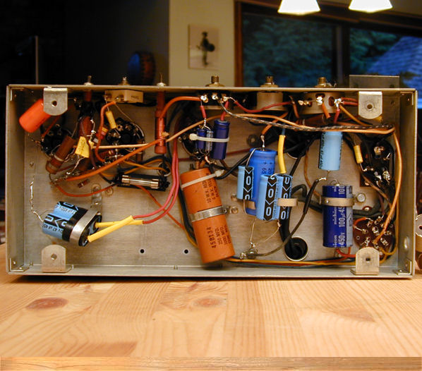
Here it is before and after recapping.


I left one of the old electrolytics in place under the power chassis
(disconnected, of course). The new caps
fit the space easily and the old case made a convenient anchor for
a plastic tie. Elsewhere, I used the original metal clamps from the old caps
to secure the new ones. Power-supply capacitors carry high voltage, so it's important to anchor
them well and insulate their leads.
I normally replace power-supply electrolytic capacitors before trying out an
old television. Sixty-year old electrolytics are invariably bad and turning on
the TV before replacing them might ruin the power transformer
or other parts.
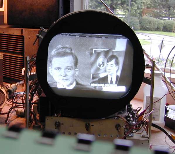
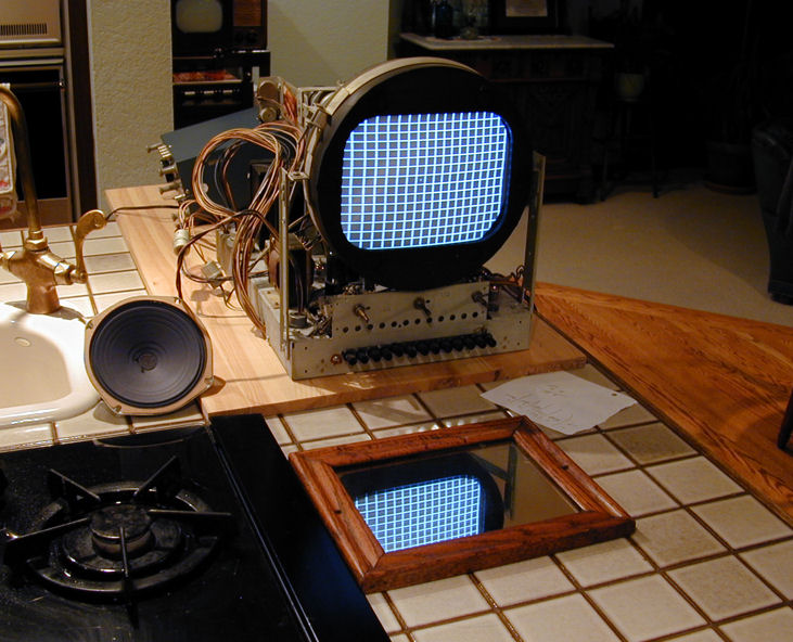
I then replaced a couple of weak tubes, reconnected the chassis on the workbench,
and slowly brought up the power using a variac. To my delight, the TV had a
bright picture and great sound. Here's how it looked like at this stage.
The picture had some distortion as well as vertical and horizontal sync problems, but that's
expected for a mostly-unrestored TV of this vintage. On the whole, things looked very
encouraging!
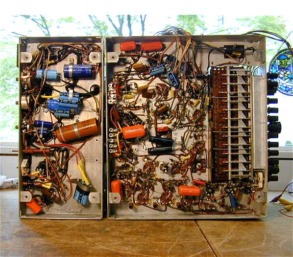
Next, I replaced the remaining paper and electrolytic capacitors in the tuner chassis. The
following photo shows both chassis with new caps in place.
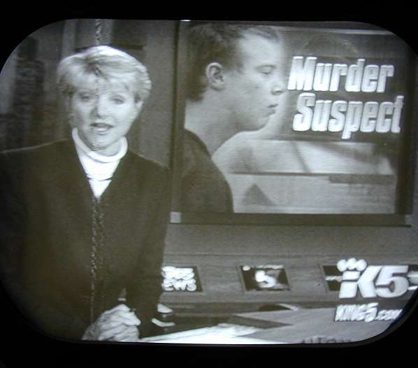
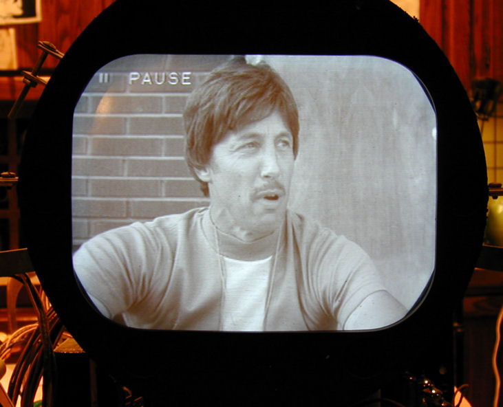
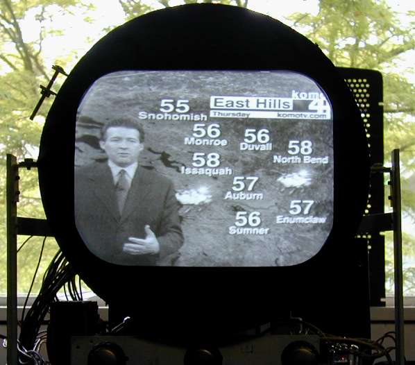
When recapping was finished, I adjusted the picture controls and was pleased with the
picture quality. One defect remained, however: a vertical line running down the left half of the
screen. In the next photo, it's visible near the news lady's nose.
I queried the rec.antiques.radio+phono
newsgroup and learned from TV veterans that this is
"Barkhausen interference," caused by unwanted oscillation from the horizontal output tube (in this
case, a 6BG6GT). The name refers to similarities
in a Barkhausen-Kurtz ultra-high frequency oscillator.
One hallmark of this interference is
that it's more prominent with weak stations than strong ones. In reading up on the topic, I
learned about other, similar types of interference with amusing names such as "snivets" and
"spooks."
The simplest cure for Barkhausen's is to substitute other output tubes until you find one that
doesn't oscillate. The 6BG6GT tube is not expensive, so I ordered a new one from Antique
Electronic Supply. In the meantime, I happened to attend a swap meet and picked up a used 6BG6GT for a couple of bucks. The used tube didn't cure the problem, but the new one eliminated it completely.
Here's the picture minus Barkhausen's.

Another solution is to place a small circular magnet around the output tube and adjust it
until the line disappears. Old-timers used spare ion trap magnets for this purpose.
My DuMont RA-103 has a small magnet mounted
in the back of the high voltage cage for Barkhausen suppression.
Once the interference was cured, several adjustments remained. I adjusted the yoke to make the picture
horizontal and touched up the oscillators for each channel to avoid
having to fuss with fine tuning every time you change stations. Then
I fired up my pattern generator to adjust the picture geometry
(height, linearity, and so on).
Now we have a crisp, bright picture.
With a new picture tube, here's a set that you can enjoy
even in a brightly lit room. The audio is strong and clear.
This is as good as any 62-year old TV gets. The spare 10BP4 will
come in handy if I run across another 10-inch TV with a dud picture tube.
Final Thoughts
If only every TV restoration could be this easy! I was lucky to find a well preserved
one-owner set that needed little attention other than cleaning the controls and
replacing capacitors.
The T-67 is straightforward to work on. The small size makes it easier to manage than
a big console. Each of the chassis can be laid on its side
for recapping and you won't find any impossible-to-reach components underneath.
If you're experienced in restoring other tube devices and you want to
try a television, this wouldn't be a bad starter set.
|