Dominion Electrohome Model 162 Console (1947)
This is a Canadian radio, built by Dominion Electrohome Industries Ltd.,
of Kitchener, Ontario. According to the label, they were makers of radio
receivers, air conditioners, fans, and Deilcraft fine furniture.
If you are looking for information about other Electrohome radios, you
could try contacting the
Canadian Vintage Radio Society.
I don't have a reference book for Canadian radios, and don't know about other
Electrohome models.
If you need a schematic for a Canadian radio, try your local public library. Many
Canadian libraries have a set of RCC (Radio College of Canada) schematics and can
provide you a copy at little or no cost. You can also order schematics from the CVRS, noted above.
This was the first console radio that I restored. What
follows is a diary of the project.
January 22nd, 1996
I found this small wooden console in the back room of a rural
shop, barely visible in the clutter. Although dingy and faded,
I could see that the cabinet was unscarred and
the finish easily restorable. I had long sought
a radio that could double as a bedside table, and,
at 30 inches in height, this one looked ideal. The color and
style made a great match with our antique dresser, and the
price was definitely right.
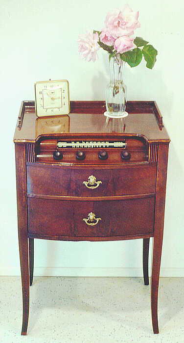
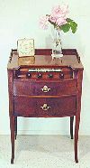
The following photo shows the radio in "before" condition, minutes after unloading at home.
The radio receives broadcast and shortwave bands and
has a slide-rule type dial with a rounded glass. The
four knobs control the radio and phonograph.
The cabinet appears to have two drawers, each with a
fancy brass pull, but the upper drawer is false. The lower
one slides out to reveal the phono turntable.
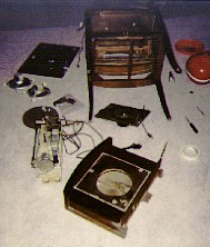
The second photo shows our patient lying on its face later
that day, after I carefully removed the major
components from the cabinet. In this view, the
phono drawer lies in the foreground, with the radio chassis
to its left. The dual speakers are visible further back.
They are mounted on the sides of the cabinet, concealed behind
metal screens painted a wood grain to match the walnut finish.
February 16, 1996
Since taking these photos about three weeks ago, I have
revived the cabinet finish using Danish oil in a walnut color.
The first step
was to clean the cabinet using paint thinner (mineral spirits)
and #0000 steel wool. Then I began applying the oil finish. For
a cabinet like this, with only minor blemishes, an application
of stain or oil is all that's needed to improve its appearance
without making it look too new.
The radio performed beautifully as found, with
good tone and selectivity. Like all such old tube
radios, of course, it will require replacement of its
old paper and electrolytic capacitors.
Although the electronic work is straightforward, I haven't yet
decided what to do with the dial glass, which is broken
in half near the center of the dial. The glass is curved,
with the dial markings painted on the back. I've seen
references to folks who can fix or replace dial glasses.
When I get a chance, I'll have to phone around to
see what's possible. While the break isn't ragged, I'm not
sure I could glue it neatly enough to make a clean repair.
April 27th, 1996
After lots of telephoning, I couldn't
find anybody who could replace this painted
glass dial. So I screwed up my courage and glued it back together.
I'm pretty pleased with the results. The dial is intact and solid,
and you have to look pretty closely to see that there was even
a crack.
Gluing the dial pieces together was a project in itself. First,
I fashioned little cardboard pads for each end of this long glass and
taped the pads on securely with masking tape. Before applying any
glue, I tested my clamp setup and used a steel straightedge to make
sure the dial would be going together straight. I used a long
woodworking clamp; the pads on the end of the glass prevented
the clamp from damaging the dial.
Then I took the pieces out of the clamp, applied the
glue (Elmer's Stix-All Hi-Technology Adhesive), and gently
clamped the pieces together again.
I rechecked the dial with a steel straightedge to make sure
the pieces were straight, and very gently
wiped away a little excess glue that squeezed out of the joint.
After letting the glue set overnight, I removed the dial from
the clamp and cleaned off a couple more stray glue bits with
a very small knifeblade. The dial has now been replaced and looks
very fine, indeed.
June 5, 1996
After several weeks of procrastinating,
I finally got around to replacing all the old
paper capacitors with new ones. I also replaced the power cord, which
was dangerously cracked at the place where it entered the chassis.
So far, so good, except that when the dust settled, I noticed a
lead hanging loose from a small transformer under the chassis. It must
have been knocked loose when I did the other work. The lead is fairly long, and
I can't tell by looking exactly where it came from. There are several
possible attachment points in the vicinity. And I saw no
broken solder joints or stray bits of wire to give me a clue.
Two of the transformer leads go to the speaker, so I'm guessing it's used
for audio output. In reach of the loose lead is the 6K6 tube, which
can be used as a power amplifier according to my tube reference book.
The book also shows the pinout and
internal wiring for the 6K6 tube. Pin 3 is the plate, a likely
connection for audio output. It's tempting to experiment, but after working
so hard on this set, I don't want to fry something through impatience.
I need to get my hands on a real schematic, or get advice from someone.
June 24, 1996
I phoned a few places asking for a schematic, but none of them
had Canadian schematics. Time for a query to the
rec.antiques.radio+phono newsgroup.
Voila! Within a few hours, I had my answer and the radio was working again.
Daniel Schoo, a newsgroup regular, advised that the transformer was
indeed the audio output transformer, and that the errant lead
should connect to Pin 3 (the plate) of the 6K6 tube. I tried it out,
fired up the set, and was back on the road again!
Another collector, Grant McGregor in Vancouver, volunteered to
look for an RCC schematic in his public library and mail me a photocopy.
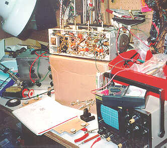
Here's a view of the radio on my workbench,
surrounded by a jumble of test equipment and tools. The chassis
is lying on its side atop a cardboard box, with knobs up in the air. The
infamous audio transformer is visible to the left of the chassis. I
don't usually work in quite such a mess, believe it or not. This is just
how the scene looked when I popped the chassis onto the bench to make
that last crucial connection.
It's the evening before we leave on a two-week family vacation.
Now that the radio's working, I'm determined to get it back
into its restored cabinet before we leave.
It's a good thing that I bagged up and labeled all the screws and
other connectors when I disassembled the radio last January. If I
had left them loose, it would have been easy to forget or mislay
things during the course of the last six months.
By mid-evening, the radio is working and reassembled. I return it to
our bedside and enjoy some tunes while we finish packing. After
we return, I'll photograph the finished set and update my notes.
July 12, 1996
After returning from vacation, I found the schematic waiting in my
mailbox. Even though the set is already working, I'm glad to have
the schematic, because it clears up a second little mystery.
The on/off switch (the leftmost knob)
on this set is combined with the tone control. The volume control is the
second knob to the left. Most radios have the opposite arrangement,
where the on/off switch also controls the volume, and the tone control
is separate.
At first, I assumed something
was wrong. Volume controls are oft-replaced parts, and
maybe some fumble-fingers had mistakenly switched things in the
course of a repair.
The schematic confirmed that this arrangement is intentional, however.
The schematic also told me the date of manufacture: 1947.
July 25, 1996
Six months after buying the set, I'm finally ready to take my
"after" photo. It's a gratifying occasion. In hindsight, had I
worked steadily on this project, it could easily have been done
more quickly. The electronic repairs took only
a few hours, including some initial testing, replacing all the
capacitors, and reattaching the loose transformer lead.
The most time-consuming part of the cabinet restoration was
applying several hand-rubbed coats of oil finish to the top.
The final result looked great, but I have since learned that
the vast majority of old radio cabinets were finished in lacquer,
which dries in minutes. In our humid Pacific Northwest climate,
I found that it took days for the oil finish to dry completely.
I will apply that lesson in future refinishing projects!
In our Restoration section, you
can read articles with more details about cabinet refinishing.
|