Sparton Model 1271 Console Radio (1939)


I found this Sparton 1271 console in the basement of a local shop, priced at $45.
The cabinet was in poor shape, but the high tube
count and large speaker suggested that it would be a good performer when restored.
So I took the plunge and hauled it home.
Based on the cabinet design and tube lineup, I'm guessing that this radio was made
around 1939. None of my collector guides gives an exact date for this set.
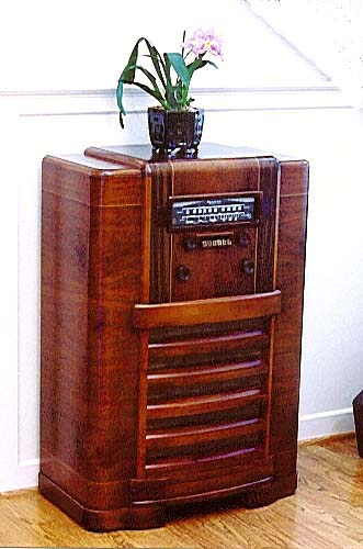
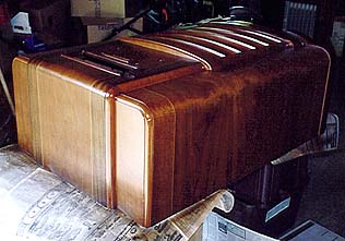
The first photo shows the radio after restoration. The handsome console cabinet uses veneer with several different contrasting grains.
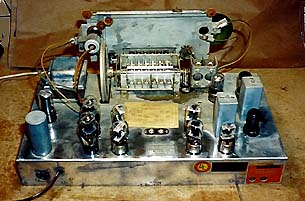
The next photo gives a rear view of the restored chassis.
This radio must have been one of Sparton's better sets of the day. It
is a two-band receiver, covering the standard broadcast band as well
as shortwave from 5.5 to 20 megahertz. Other features include an RF amplification stage,
pushbutton tuning, and a tone control.
With a generous twelve-inch speaker and push-pull audio section, this is
a great-sounding radio. The built-in antenna is a bit unusual, consisting of
two rectangular metal plates bolted on either side of the cabinet interior.
You can also connect an external antenna for improved shortwave reception, of course.
Cabinet Restoration
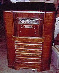
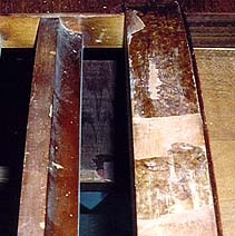
The next photo shows the radio right after I brought it home.
Although basically intact, the cabinet was very weathered on top
and had a number of small nicks and dents elsewhere. Someone had
evidently put a potted plant on the top, causing the lacquer
finish to flake away down to the bare wood. Some of the top veneer had
also separated due to moisture, creating a couple of large
raised "bubbles."
The beefy grille louvers also showed considerable damage. They were
covered with a "photo-finish" decal, which is the bane of radio restorers.
Once the decal has been scraped and scratched, as this one was, it is
almost impossible to restore to its original appearance.
Other radios of mine with photo-finishes are the Zenith 6-J-230
and Philco 37-61. Both of those radios dates from
the late 1930s, giving another clue to when this set was probably manufactured.
A talented artist who knows how to paint "faux finishes" can carefully
fill the scraped areas and repaint them to match the remaining decal pattern.
I don't have that kind of skill (or patience!), so I reluctantly decided to
strip at least that part of the cabinet—or possibly the whole thing.
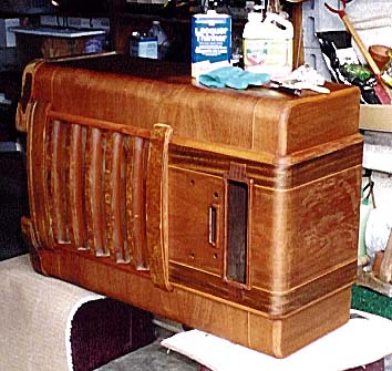
The next photo shows the cabinet after I had started removing the old finish.
Rubbing the weathered top with lacquer thinner removed the remaining finish. To fix
the bubbled veneer areas, I cut a tiny slanted opening in each bubble with a razor blade,
carefully injected glue, and then clamped the bubble flat until the glue dried. The
opening had been cut on a slant, so when the veneer was reglued, the cut became
invisible.
The next photo shows the louvers with some of the old decal removed.
I first tried stripping off the damaged decal with Citri-Strip, a gentle gel-type stripper.
While the stripper removed the outermost, patterned layer of the decal, a tough paper
layer, saturated with the original glue, remained firmly stuck to the louvers. At this
rate, it might take days to remove the decal.
Time to bring out the heavy artillery! I opened up a can of zip-strip, a very
caustic paint stripper. This solution worked somewhat better than Citri-Strip,
but my progress was still painfully slow.
After a couple of hours of work with the stripper, making a horrible mess, I gave up.
It would be faster and cleaner to simply scrape off the decal by hand.
Scraping requires caution and a steady hand, so that you don't gouge the underlying wood.
Once you have the hang of it, however, you can remove many finishes as slick as a whistle.
I use an old putty knife that belonged to my Grandpa. Its blade has worn to exactly the
right shape to scrape old finish efficiently without chopping the wood.
Eventually, the old decal came off. At that stage, it became apparent that I'd get more
even results by lightly stripping the remainder of the cabinet (i.e., the sides and front).
I went over these portions lightly with lacquer thinner, which did not remove all the
old finish but did make these parts consistent with the previously stripped areas.
At long last, I had a clean cabinet ready for refinishing.
The next photo shows the cabinet at this stage.
As I had expected, the wood underneath the fancy decal was cheap "construction" wood,
lacking interesting grain. To blend their color with the rest of the cabinet, I would
need to mask the other portions and spray some extra brown toning lacquer on them.
I also gave the entire cabinet a light application of medium brown toning lacquer.
This makes the color even but does not obscure the pretty grain.
The next photo shows the cabinet when I was applying one of several finish coats
of clear lacquer.
In between each coat of lacquer, I lightly buffed the whole cabinet with super-fine (#0000)
steel wool, then carefully vacuumed it to remove all dust and steel wool particles.
Refinishing a console cabinet is a lot of work. I would never invest this amount of
effort on a cabinet that had only a few small dings. Those can easily be touched up,
and you will preserve more of the radio's original character.
My radio was missing one of its wooden knobs. I was very fortunate to get a replacement
from Eddie Brimer, who borrowed one of the originals to use as a pattern (thanks, Eddie!).
After I got the new knob, I gave all four knobs a light application of toning lacquer,
followed by two clear finish coats. By the time I was done, I couldn't tell the
reproduction from the originals.
Electronic Restoration
Here is the tube lineup for the Sparton 1271.
|
Tube |
Type |
Function |
|
V1 |
6SK7GT |
RF amplifier |
|
V2 |
6SA7GT |
Oscillator/converter |
|
V3 |
6SK7GT |
IF amplifier |
|
V4 |
6SQ7GT |
Detector/AVC/audio amp |
|
V5 |
6P5GT |
Phase inverter |
|
V6 |
6P5GT |
Driver |
|
V7 |
6P5GT |
Driver |
|
V8 |
6AC5G |
Power amplifier |
|
V9 |
6AC5G |
Power amplifier |
|
V10 |
6P5GT |
AVC amplifier |
|
V11 |
6AF6G |
Dual Viso-Glo (eye) |
|
V12 |
5Y3G |
Rectifier |
Most of the electronic restoration involved no surprises. I replaced
all of the electrolytic and paper capacitors and aligned the radio, as usual.
(See our recapping article for more info on
capacitor replacement.)
The "magic eye" tuning indicator on this radio is a bit unusual. It employs
a type 6AF6G tube rather than the more common 6U5 or 6E5. An advantage of
the 6AF6G is that it has two electronic shadows. A 6U5/6E5 with a single
shadow has only one pie-shaped region that closes up as you tune in
a station. The 6AF6G shows two opposing pie shapes, giving a more symmetrical appearance.
What is more, the eye circuit can be adjusted so that the shadows have
a slightly different response, giving greater precision when tuning in
distant stations. You can read more about tuning eyes in my
magic eye article.
The tuning mechanism required a bit of extra work.
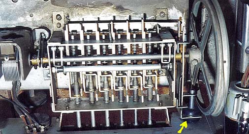
The next view shows the tuning gear. At the left you can see part of the tuning
capacitor. The shaft of the tuner runs all the way through the central pushbutton
mechanism, to the large tuning pulley on the right. (In this view the front of
the chassis is at the bottom of the photo.)
In the previous photo, the yellow arrow points to a rubber drive wheel that rubs
against the large pulley. When you turn the tuning knob, the drive wheel's friction
turns the big pulley, causing the tuning capacitor to move.
When you push in a tuning button, a clutch disengages the rubber drive wheel from the
large pulley and a rather Rube Goldberg-like system of levers and arms moves the tuning capacitor to a preselected position.
The old rubber drive wheel had worn out and hardened with age, so the tuner slipped
when I purchased the radio. The only solution was to fashion a new rubber wheel.
At the local hardware store, I found a rubber plumbing washer of approximately the
right size. Using a razor blade, I carefully cut a bevel along one side, matching
the original part.
The internal diameter of the new wheel was slightly too large, so I cut a small length
of rubber band to exactly the right length and glued it inside the wheel
using cyanoacrylate glue. The next photo shows the old and new wheels, along with
the materials that I used.
The last step was finicky: slipping the new rubber wheel onto the knob shaft
without tearing loose the carefully glued liner. Working slowly, I finally got the
wheel onto the right place and reinstalled the shaft. To my delight, it worked perfectly!
Mechanical pushbutton tuners are not a great solution. No matter how carefully you
set the tuning, it will eventually go out of adjustment due to wear and slippage
in the mechanism. A better system is electronic tuning, such as you'll find in
my Zenith 12-S-471 console. In this scheme, the button does not
manually move the tuning capacitor. Instead, it switches in a little coil-capacitor circuit that changes the tuning electronically.
After setting the pushbuttons, it was time to reinstall the chassis and enjoy my
newly restored Sparton. One of these days, I may get around to the final
cosmetic touch, printing out little paper labels with station call letters
for the pushbuttons. I have several pushbutton radios with original labels
for this area, so I know exactly which stations to use.
A couple of years after restoring this radio, I sold it to a fellow
collector for $100. That was a very low price, considering all the labor I
had invested, but it was time to make room for a console that I liked
even better!
|