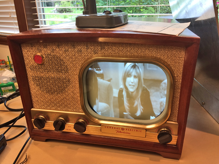
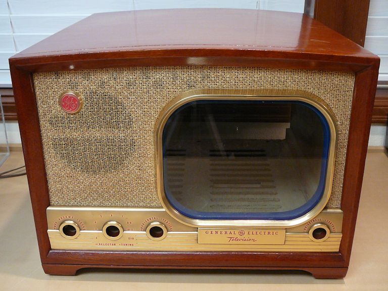
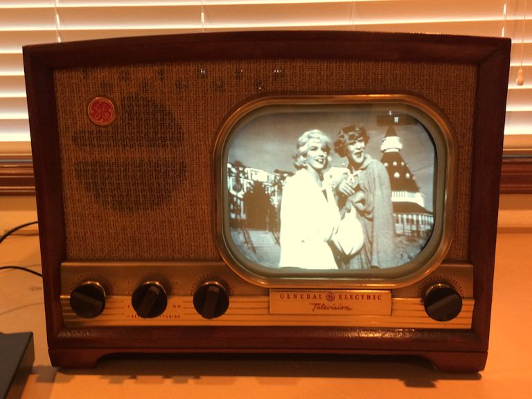
General Electric Model 810 Television (1949)


This General Electric Model 810 television is a classic 10-inch
set from 1949. The styling is dramatic, with
a lustrous brass control panel and outsized fabric grille.
Description
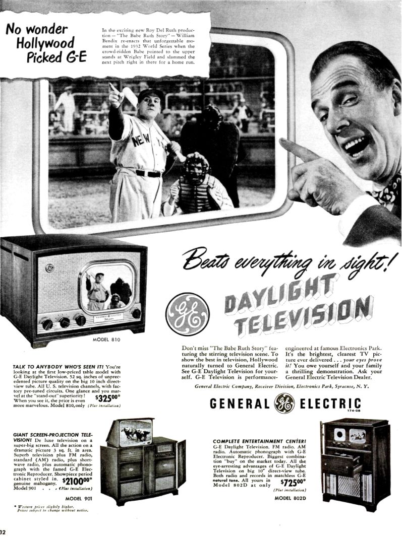
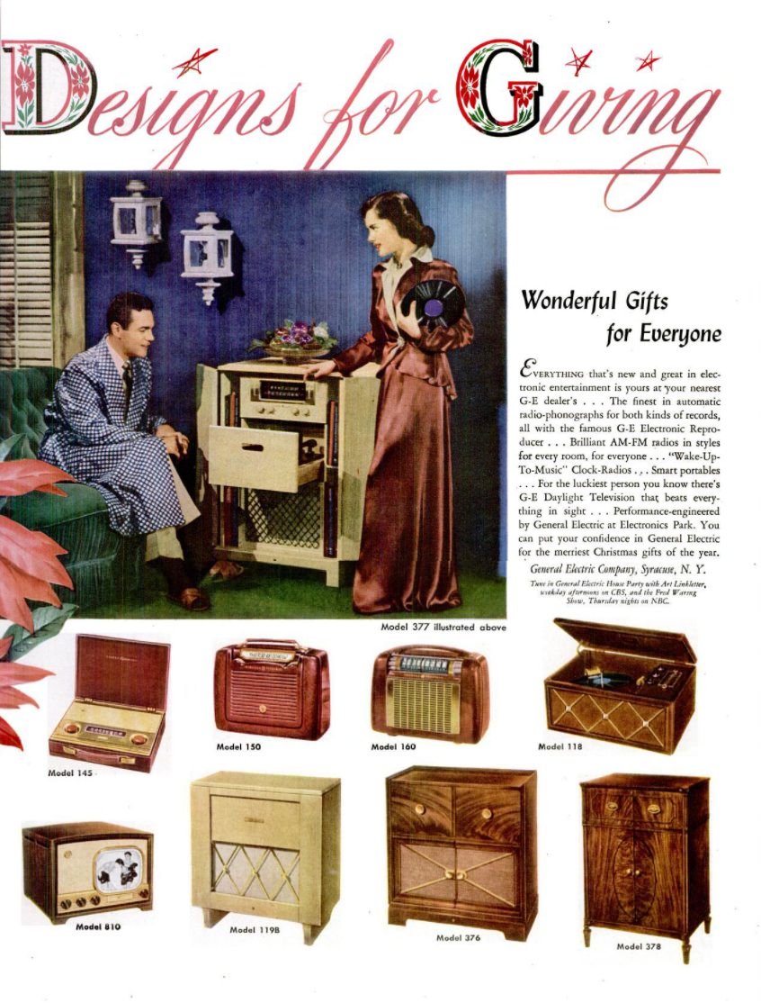
Model 810 was one of GE's first TVs and it was promoted heavily in these
glossy full-page Life magazine ads from 1948:


The post-WWII era saw explosive growth in the emerging
TV industry, and every manufacturer wanted to put its TVs into
American homes. The GE 810 was targeted at first-time TV buyers,
offering a (comparatively) big 10-inch "daylight" picture in
a compact tabletop cabinet, at an entry-level price of only $325.
The 810 was a big seller, judging by the number that
survive today. It's one of the most common 1940s GE TVs,
along with model 800 and one or two others.
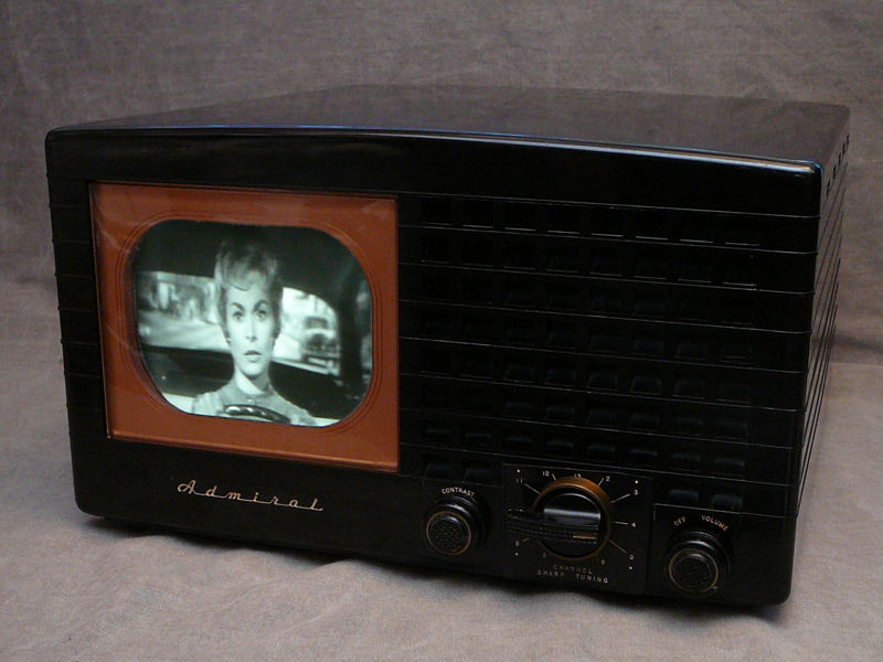
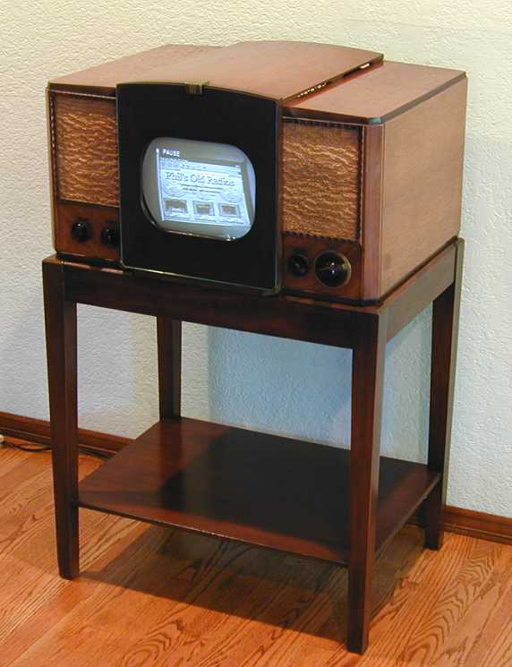
For a tabletop TV of this vintage, the GE 810 is a middleweight. It's larger than
a 7-inch set like my Admiral 19A12 (left), but more compact
than my 10-inch RCA 630TS (right), which can live on
a tabletop or a stand:

The model 810 television uses 22 tubes:
| Tube |
Type |
Function |
| V1 |
6AU6 |
RF Amplifier |
| V2 |
12AT7 |
Converter/Oscillator |
| V3 |
6AU6 |
1st Video IF Amplifier |
| V4 |
6AU6 |
2nd Video IF Amplifier |
| V5 |
6AU6 |
3rd Video IF Amplifier |
| V6 |
6AL5 |
Video Detector/Clipper Rectifier |
| V7 |
12AU7 |
Video Amplifier/Limiter |
| V8 |
10FP4 |
Picture Tube |
| V9 |
6SN7GT |
Vertical Sweep Generator |
| V10 |
6V6GT |
Vertical Sweep Output |
| V11 |
6SN7GT |
Phase Inverter/Clipper |
| V12 |
6SN7GT |
Horizontal AFC/Sweep Gen. |
| V13 |
6BG6G |
Horizontal Sweep Output |
| V14 |
1B3GT |
High Voltage Rectifier |
| V15 |
5V4G |
Horizontal Damping |
| V16 |
5U4G |
Low Voltage Rectifier |
| V17 |
6AU6 |
Audio IF Amplifier |
| V18 |
6SH7 |
Audio IF Limiter |
| V19 |
6AQ7GT |
Audio Discriminator/Amplifier |
| V20 |
6K6GT/G |
Audio Output |
| V21 |
5Y3GT |
Low Voltage Rectifier |
| V22 |
6AU6 |
Audio IF Amplifier |
Here are the Riders and Sams service manuals for this set:
(These manuals, along with many others, are hosted at the
Early Television Foundation website.)
Finding a GE 810
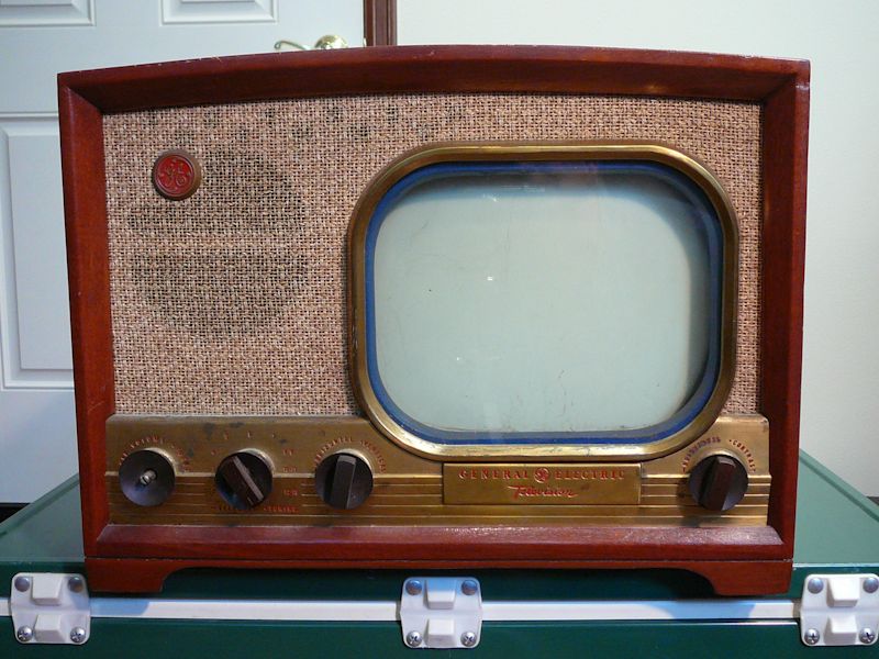
I spotted this TV in a local Craigslist ad
in Spring, 2018. The TV was listed for $75, but the listing disappeared before I got
around to contacting the seller. Next week, the ad reappeared, and the price was
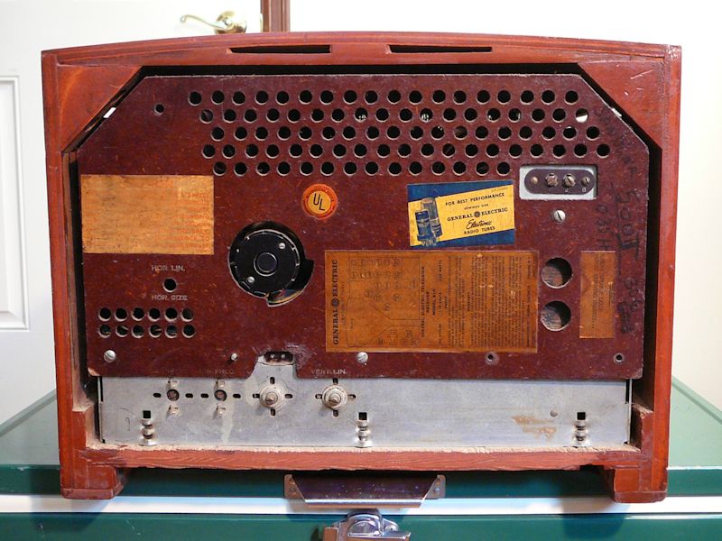
reduced to an irresistible $25! Here's my 810 when I got it the next day:

The cabinet is in decent condition and it includes the oft-missing back cover.
We'll get a peek at the internals soon.
First Look
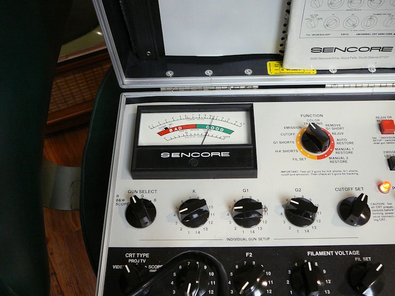
Before investing too much effort in this set, I need to test the picture tube; if it's
a dud, replacing it might cost $100 or more. This TV uses a
10FP4 tube, an
aluminized jug that produces a bright picture if in good shape.
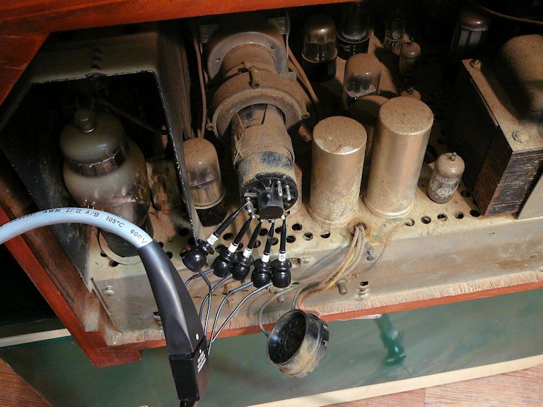
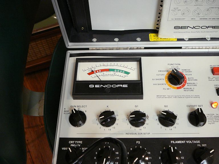
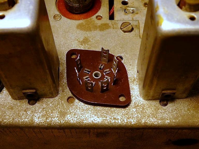
I slid the socket off the end of the picture tube and connected the clip probes
of my Sencore CR70 CRT tester:

As often happens with long-unused picture tubes, this one looked nearly dead
at first. But the emission needle crept upward when I let the tester run for a while,
and it ended up in very respectable territory. If I can get the rest of the TV
working, I expect it to make an image with good brightness and contrast.


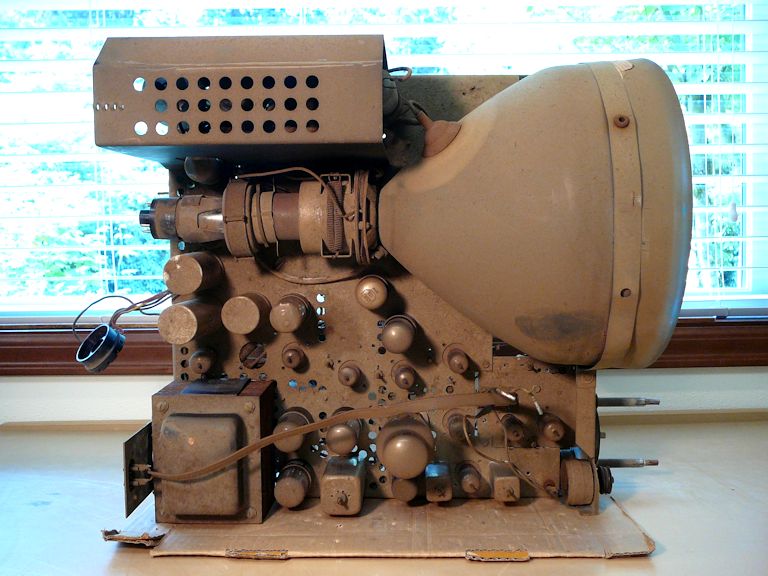
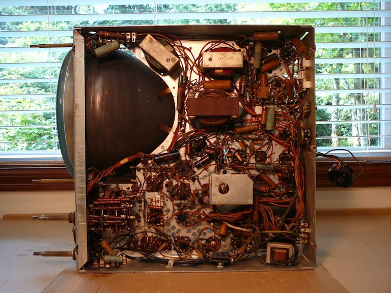
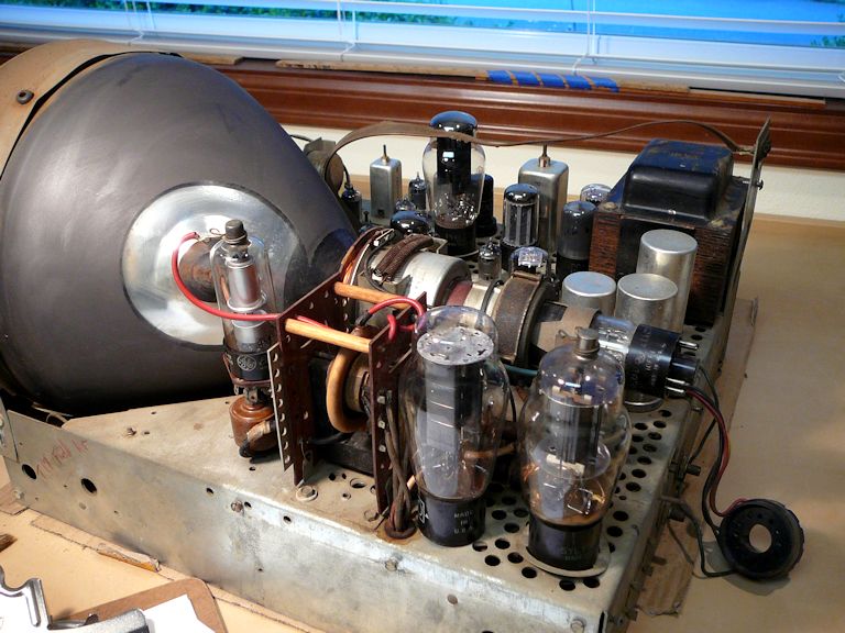
That's an encouraging sign. Let's pull the chassis and get started! Here are
photos of the unrestored chassis from above and below:
Yes, you can stand this chassis sideways on the workbench (power transformer down), but
it's rather tippy with that heavy CRT in place. During parts of this project where the big
tube isn't important, I'll pull it and substitute my smaller 5AXP4 test CRT.
The next step is to test and clean the TV's 21 small tubes. As described in my
first restoration steps article, it's
convenient to clean the chassis as you go along.
Of those 21 tubes, only one was bad. Our chassis looks better after this initial cleanup.

Using DeOxit, I cleaned all the TV's potentiometers and the contacts in the tuner.
First Power
Like every 1940s TV, this one is full of old paper and electrolytic capacitors that
should be replaced for safe and reliable service. (For more information about capacitor
replacement, see my recapping article.) My workshop stash didn't
have all the needed caps, so I compiled a list and made an online order.
Meanwhile, I'm curious whether I can coax any signs of life from the unrestored set.
I don't often do this, but I decided to try powering it up without even replacing
the electrolytics in the power supply. Being an optimist, I turned the channel
selector to channel 10, the one that I use to broadcast throughout the house with my
home TV transmitter.
I didn't just turn the set on, however. It's prudent to start up an unrestored TV using a
variac, gradually increasing the line voltage
while keeping a close eye on the TV's current consumption. If the current draw is
excessive (suggesting a short circuit somewhere), you can quickly power down before
damaging a power transformer or other components.
For this first trial, I left the big 10-inch CRT in the chassis.
Things sounded good at first. I gradually turned up the line voltage and heard nothing
but a few faint crackles, until the audio kicked in, at around 90 volts AC. It
sounded good enough to understand dialogue in the program on channel 10.
When the voltage reached about 100 volts AC, I could faintly hear the sweep circuits
starting to run. But the CRT remained completely dark, and a peek at the CRT's base
revealed the reason: the picture tube's filament was not glowing, possibly due to a
loose filament pin in the base. Without power to its filament, the tube can't operate
at all.
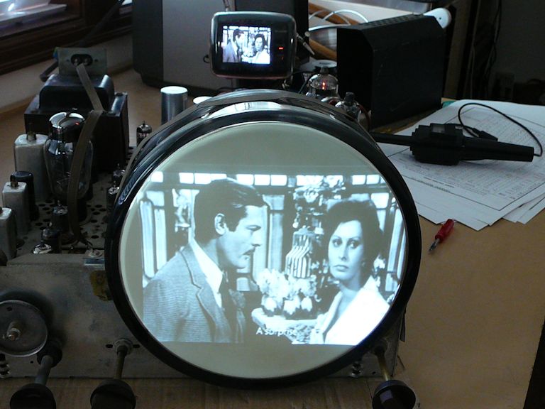
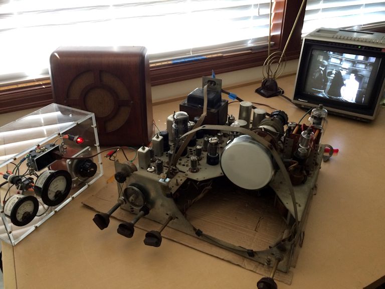
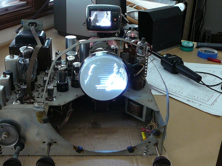
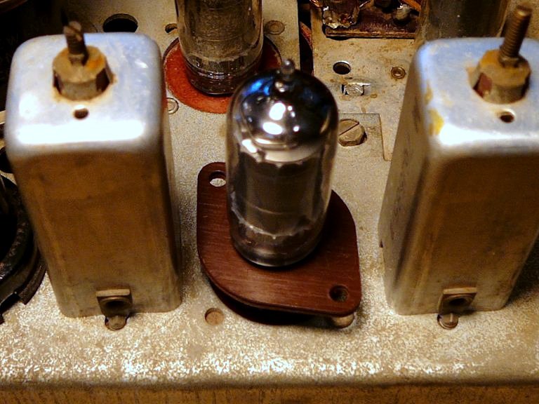
I pulled that CRT and set it aside for future investigation, installing the little 5AXP4
tube in its place. Here's the setup, with my metered variac on the left and a test
speaker connected to the audio output. I tuned the GE to channel 10, the same
channel playing on another TV in the background.

I increased the voltage slowly, giving the 71-year old electrolytic capacitors
a chance to re-form if they're able. When I reached around 100 volts, I was
rewarded with some light on the screen. Hooray!

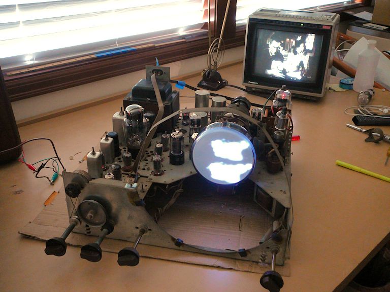
Okay—it's not the greatest picture in the world. But remember, this TV is
completely unrestored, except for replacing one dead tube. And we can tell
a lot from this brief trial, even though the screen looks like blobs.
The screen lights up and the audio is respectable. That tells us the power supply
(including high-voltage supply) is working, and
every section of the TV can pass a signal and process it, from front to back. The contrast
and brightness controls have an effect when I move them, as does the fine-tuning control.
The image is badly out of focus, but I'm using a substitute picture tube and haven't
yet adjusted the focus coil on its neck.
The horizontal hold control works normally, but the vertical sweep has major problems.
I can't lock the image vertically and, as seen in the previous photo, there are
two identical blobs stacked vertically, a sign that the vertical oscillator is
running at roughly half the correct speed.
Vertical problems are very common in old TVs, and this kind of
problem often clears up up naturally when you recap the vertical circuits.
All in all, this brief initial test is encouraging. Unless some hidden problem appears,
I expect the restoration to be straightforward.
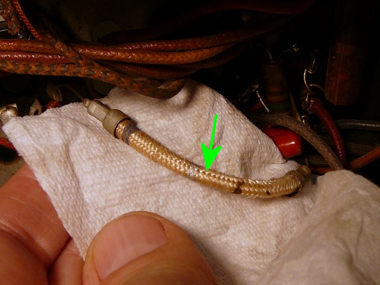
Rescuing the Picture Tube
Let's try re-flowing the solder in the pins of the
picture tube. If that doesn't succeed, I'll need to look for a replacement,
which might be costly.
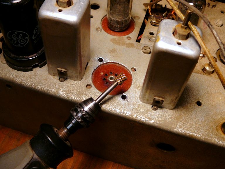
The next photo shows the basic idea. Using a soldering gun or iron, you heat
each of the tube's pins until the solder flows inside, adding a little solder if
needed to make sure that the pin is full.

Don't heat the pin more than needed to re-flow the solder; excessive heat can crack
the glass in the tube neck. When you're done, make sure that the end of each pin is neatly rounded,
as it was before; use fine sandpaper if needed, to remove any excess solder.
I re-tested the CRT, and it looked great! Remember this simple trick, if you have a picture tube
whose filament doesn't glow on the tester. Five minutes with a soldering gun may save you the
cost of a new picture tube.
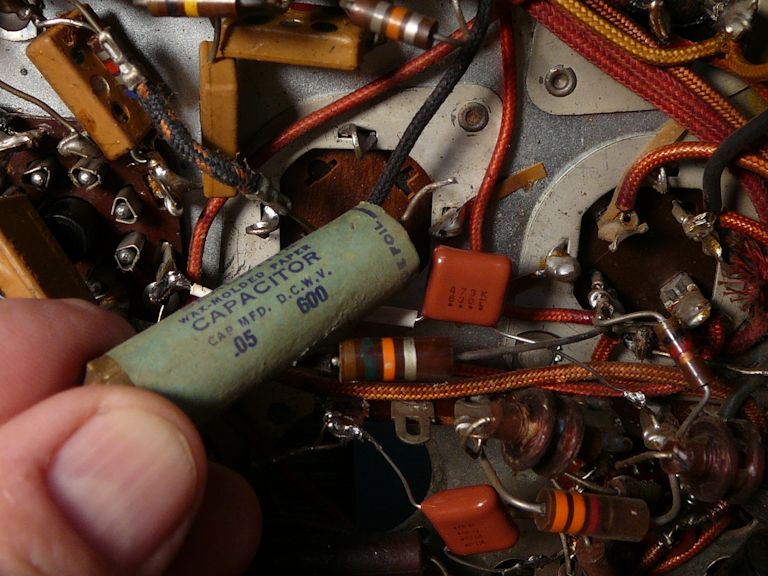
Replacing Paper Capacitors
Now, I'll start replacing this TV's 38 paper and electrolytic capacitors. In this photo,
the two brown Chiclet-shaped caps are new (and much smaller than the old paper one that
I just replaced).

The value 473 printed on the new cap denotes the value .047 mfd, functionally equivalent to
the .05 mfd value printed on the old one. Its voltage rating of 630 volts slightly
exceeds the original 600-volt rating. My recapping article
has more details about choosing and installing replacement caps.
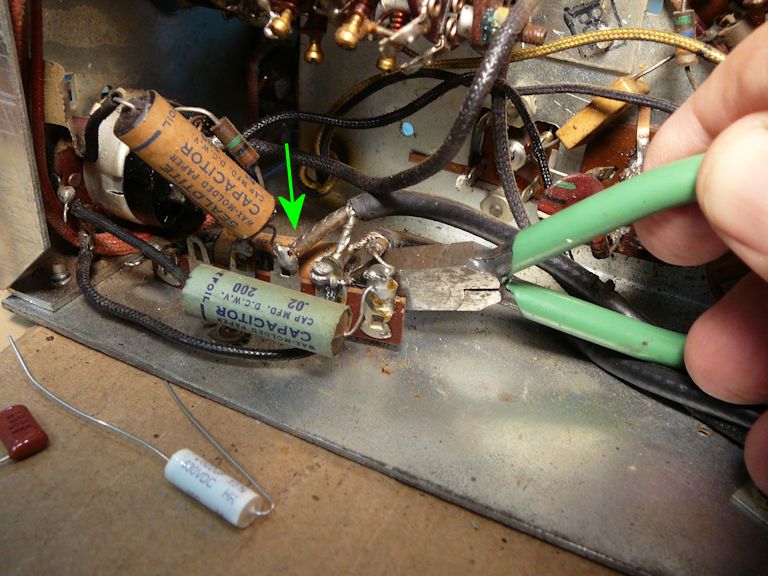
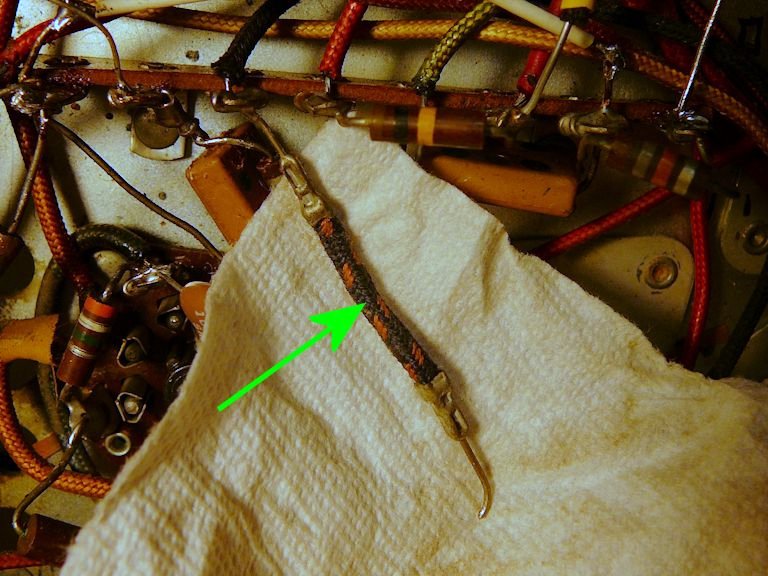
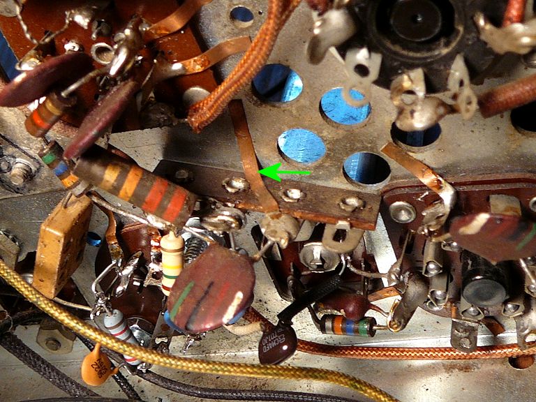
Here's a cap near the volume control that would be easy to overlook. Follow
the green arrow to spot the tan paper cap hidden behind the little terminal strip.

In the next photo, I have replaced all three of the paper caps seen in the last shot,
bringing the hidden one into the open to simplify future service.

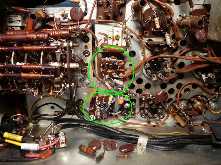
The audio output circuitry is cramped, with one small electrolytic (C93) and two paper caps
(C77, C79) in tight quarters. These photos show the area before and after replacing those
three components:


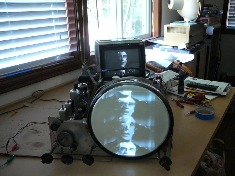
Fast forward a few hours, and we've made progress. Here's the TV after I
replaced nearly all the paper caps (but no electrolytics):

The picture looks better, but the vertical problem remains. Here, we see
three stacked images. The vertical oscillator is running at roughly one-third
the normal speed: about 20 cycles per second, rather than 60.
Fixing the Rolling Vertical
Vertical circuits are often easier to debug than horizontal ones.
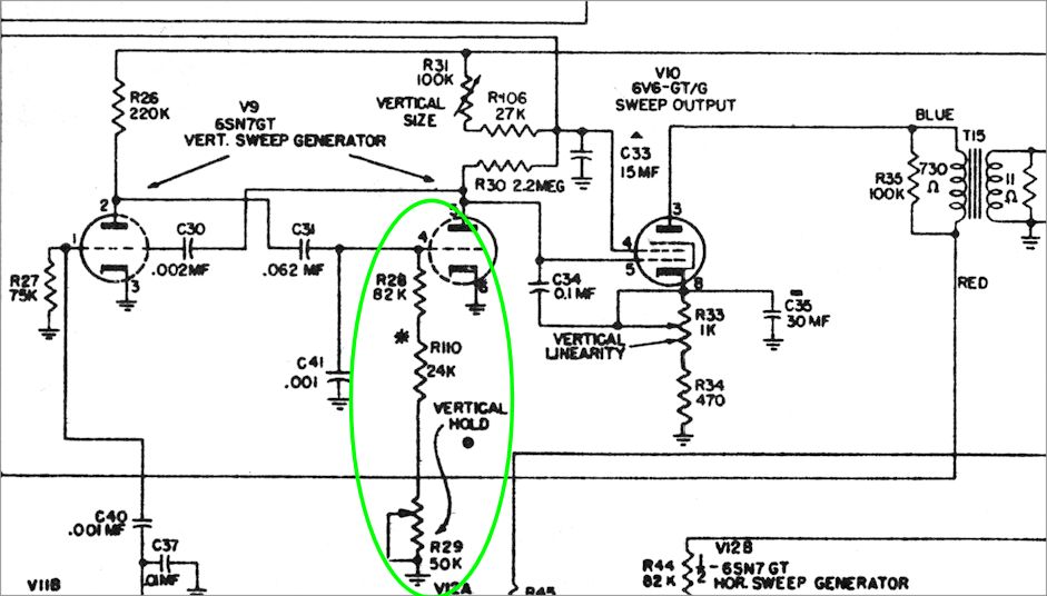
The following schematic shows the heart of the vertical section, a conventional
"multivibrator:"
Recapping had eliminated some obvious suspects from this circuit: paper capacitors C30,
C31, C41, and C34. I also tested the vertical output transformer (T15) with an ohmmeter
and found nothing amiss. I checked all the resistors and didn't find anything wildly out
of tolerance, although I did replace a few that were somewhat over the line.
After replacing those resistors, the vertical almost worked, meaning that I could sometimes get it
to lock by turning the vertical hold control all the way clockwise and adjusting other controls
very, very carefully. That's not how the TV should work, though.
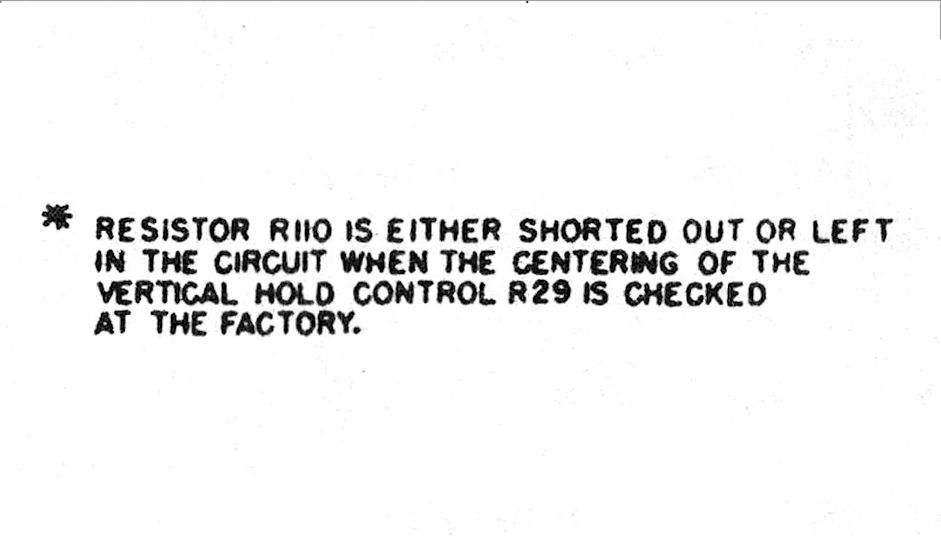
Then I noticed the asterisk next to resistor R110 in the previous schematic. Way down
in the lower right corner of the schematic is this little starred footnote:

Looking back at the schematic, we see that resistor R110 is a 24K resistor in series with
R28, an 82K resistor lying between the vertical oscillator's grid and the vertical hold
control. When I shorted out R110 (effectively removing it from the circuit), the
vertical hold improved at once. I could easily lock the vertical and the locking point
was near the center of the control's range, as it should be.
At last, we have a stable picture! The video's a bit smeary, but it's still early days.

Replacing Electrolytic Capacitors
Although the TV played safely (in short trials) with its original electrolytic
capacitors, I know from experience that 70-year old electros aren't trustworthy for the long haul.
Even if they seem OK, they can fail at any moment, in
the worst case frying the TV's costly power transformer. Out they go!
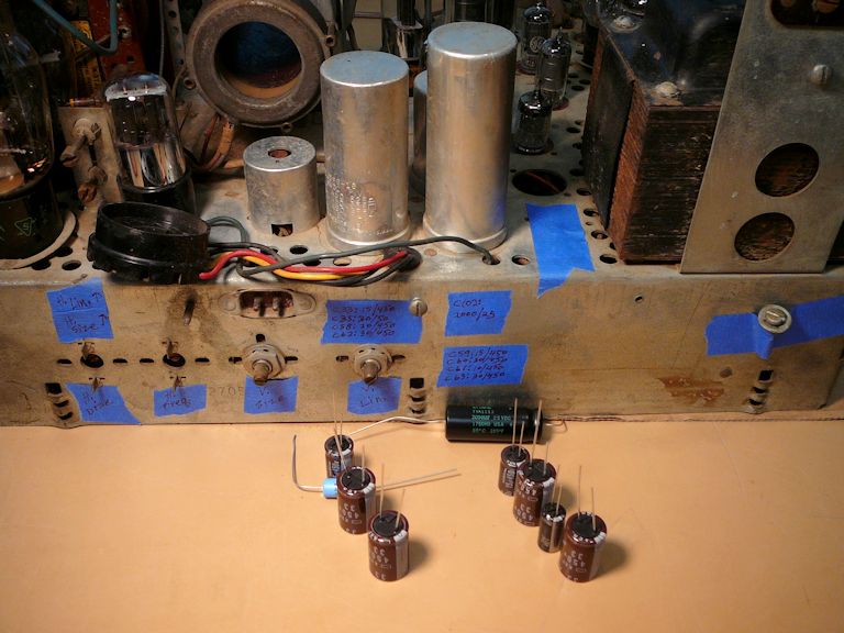
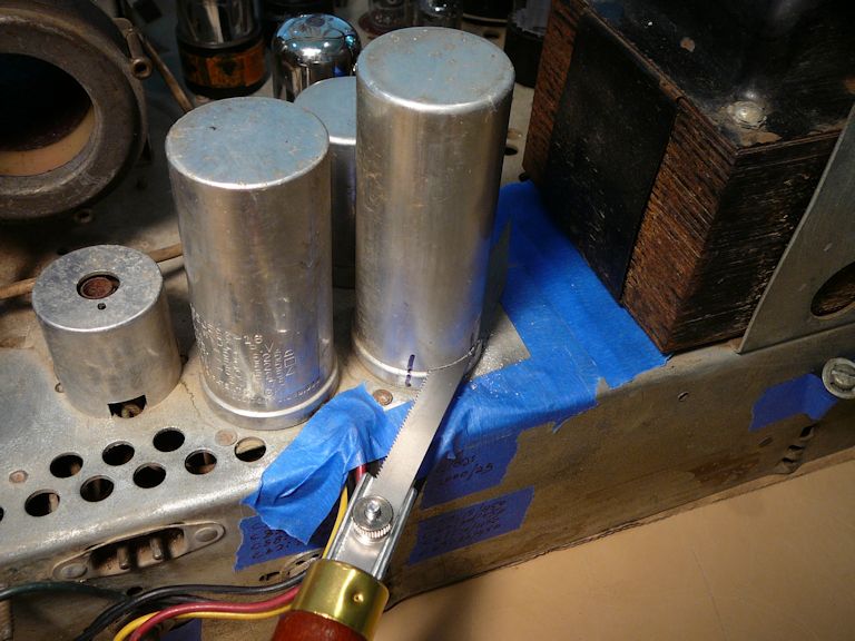
This set has ten electrolytic capacitors, eight of which are contained in a pair
of cans on the rear of the chassis. This photo shows most of the replacements;
eight will go into the tall cans and two more will go under the chassis.

After removing the cans, I'll install new caps on the original bases and then put the hollowed-out cans back
in place, another procedure described in my recapping article.


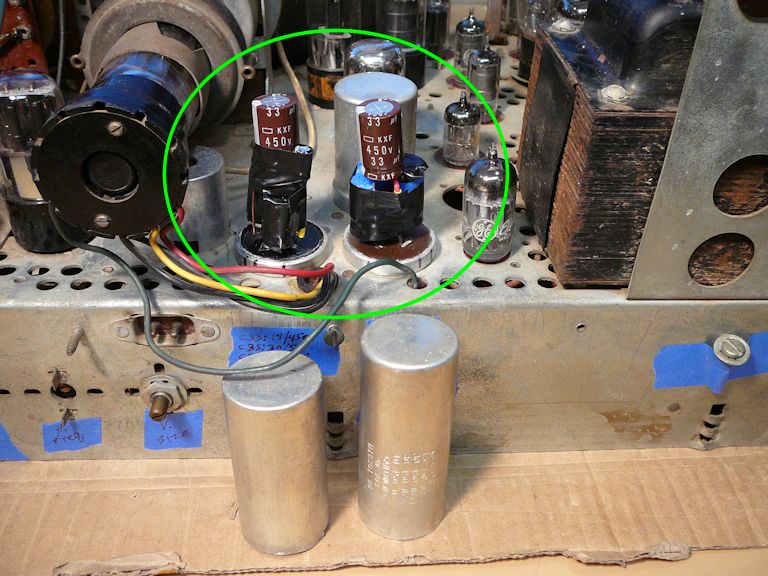
The new capacitor leads run through holes drilled in the bases, and then
they are soldered underneath to the original terminals.
Here are the replacements installed on their bases, ready for the cans to be glued back on.

Check Out These Flexible Resistors
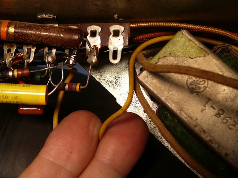
While replacing an electrolytic (C102) under the chassis, I encountered this
unusual component:

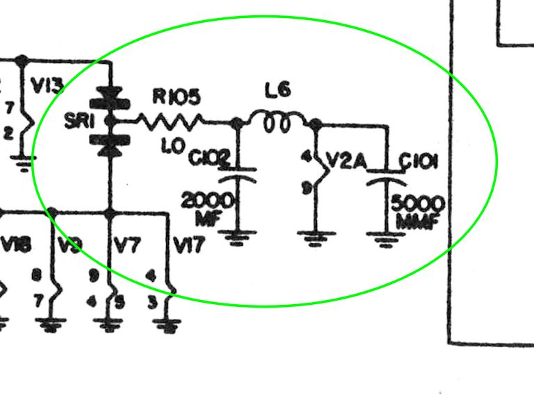
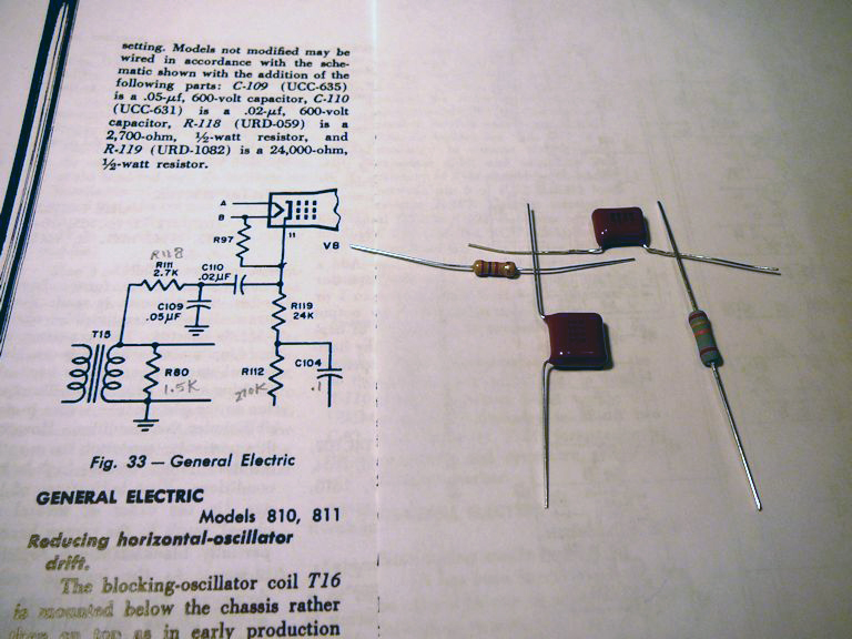
This is a flexible resistor (R105) with a very low—and precise—value of 1.0 ohms.
It is labeled R102 in this unusual circuit, which supplies filament voltage to a single tube:

In the words of the service manual:
To prevent hum modulation by the local oscillator when operating on the high
frequency channels, the filament supply to (converter/oscillator tube) V2A is
rectified by the selenium rectifier SR1 and filtered by C102:
Hum is a bad thing, but I haven't seen a circuit like
this in other TVs. I wonder if GE added it to cure a hum
problem unique to this design?
Flexible resistors are thin coils of resistive wire in flexible "stockings," usually
with low resistance values. You can read more about them in my
Stewart Warner 1865 article.
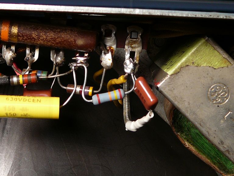
A second flexible resistor with even lower resistance (0.65 ohms) is used
in one of this TV's low-voltage power supplies. Here is R97:

Both resistors checked out fine, so I left them alone. If you need to replace
one, use a standard modern resistor with the specified resistance and wattage.
Crashing and Burning
At this stage, the TV displayed a coherent picture. These photos show it using my small
5AXP4 test CRT and the full size 10FP4 tube:

Some issues remained. Most obviously, the TV suffered from an intermittent snap-crackle-pop
that made hash on the screen and noise in the audio.
Moving the tuner affected this interference, so I cleaned all the tuner
contacts a second time with DeOxit. This reduced the crashing but didn't eliminate it.
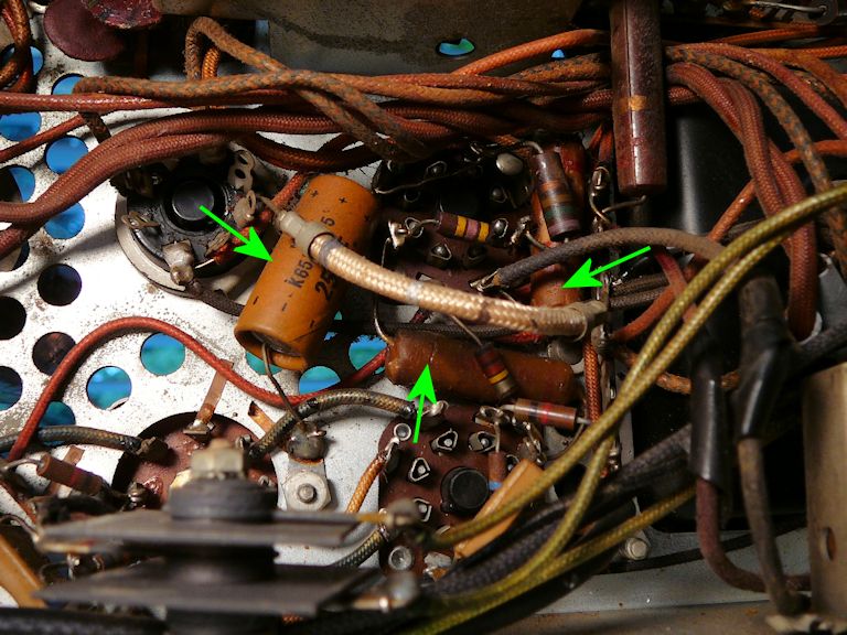
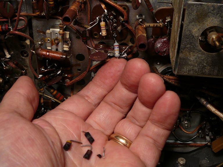
I began to make systematic voltage and resistance checks, working my way along the
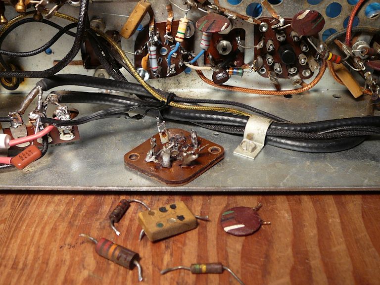
signal path. It didn't take long to find more problems. On pins 6 and 7 of V4, the
6AU6 2nd video IF amp, I found (and replaced) two resistors. They were so badly
burned that they fell into pieces when I removed them:

I should have noticed those toasted guys in my initial inspection. In any case,
they're gone now. But the crashing was still audible when the TV warmed up.
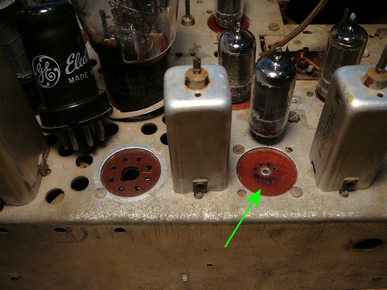
On a hunch, I turned off the lights and powered up the TV
in darkness. During the initial power surge, I saw flickering
on the socket of V7, the 6AU6 second audio IF amp.
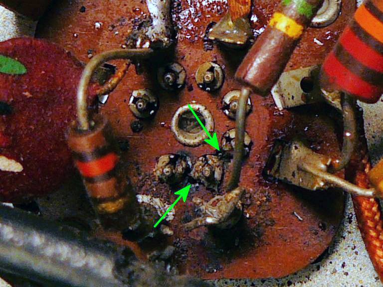
I cleaned that socket with isopropyl alcohol, then probed around the socket pins
with a dental pick, looking for burned spots. Between pins 6 and 7, I dug out
black, charred phenolic, the result of arcing between the pins:
Arcing between pins 6 and 7 of a 6AU6 tube creates a short circuit between the tube's grid
and cathode—not what the designers intended!
I dug out as much black stuff as I could reach in that cramped area, and briefly
tried the TV again. Sometimes, if the arcing damage isn't too great, you can remove the conductive
carbonized material and leave an air gap large enough to prevent arcing. Then
you can fill the gap with non-conductive epoxy and salvage the socket.
When I tried the TV again, the arcing in that spot was even brighter, a sign
that the socket still has a conductive carbon track that I can't reach. Time
to find a new socket!
Replacing a Burned Socket
This phenolic base of this odd socket is wider than normal for a
7-pin tube, indicating that the chassis was originally punched for a standard 8-pin
tube like the octal 6SH7 right next door:

I couldn't find a replacement socket from the usual suppliers, but I eventually got one
from a fellow collector. It fits!


The old socket was fastened with rivets, which I removed by grinding down their heads.
(Trying to drill out a rivet often just spins it in place as soon as the
drill bit digs in.)

I replaced all five components attached to the socket:


Why did this socket fail in the first place? There's no way to be sure. Liquid such as mouse
urine in the socket might cause a short between pins, but the chassis has no
obvious staining or rust in that area. Or, the
socket might have degraded all on its own; these cheap wafer-type tube sockets
are near the bottom of the quality scale. (At the top end,
you'll find expensive ceramic sockets like those in my National TV-7W.)
Whatever the origin, once arcing starts, it can burn a carbon track along and then into the
phenolic, as happened with my old socket. But my brand-new replacement should last indefinitely.
Losing and Regaining Audio
With the new socket and components in place, I tried the TV again.
The audio quality was good, indicating that I hadn't made wiring errors
and the audio alignment was still within the ballpark. I still heard
crackling, however.
I resumed the systematic voltage testing that was interrupted when I noticed
arcing. This required playing the TV, of course. At some point in this process, the audio
weakened and then went silent.
What's going on? I tested all the audio tubes, to rule out a sudden tube failure (they
were fine). Touching a powered soldering gun to the middle terminal of the
volume produced a loud buzz, a normal response showing that the audio
output section (with 6K6 tube) worked.
That left the two 6AU6 IF amps and the 6AQ7 discriminator.
I re-checked the voltages on the audio tubes and didn't find dramatic changes from
the last testing round. However, I was reminded that the plate voltages were
high on both IF tubes. On V22 (1st IF), the voltage should be 100V and I measured 140V. On V17 (2nd IF),
it should be 105V and I measured 195V.
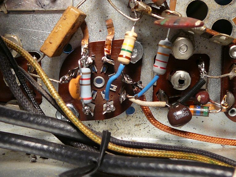
That led to more resistor testing around the audio tubes. I eventually
found an intermittent solder joint on a pair of joined terminals on a
terminal strip near the audio IF tubes, where several components connect
to a B+ line. Nudging that crowded junction changed the resistance
reading, indicating a cold or broken joint. In this photo, the junction is
largely hidden by a big 22K resistor.

The green arrow points to an example of sloppy work at the factory. The foil
ground strap appears to physically touch the adjacent terminal, a terminal
that is not supposed to be grounded! I guess that terminal wasn't
actually grounded—if so, the entire B+ line would short out—but
this slapdash handiwork doesn't inspire confidence.
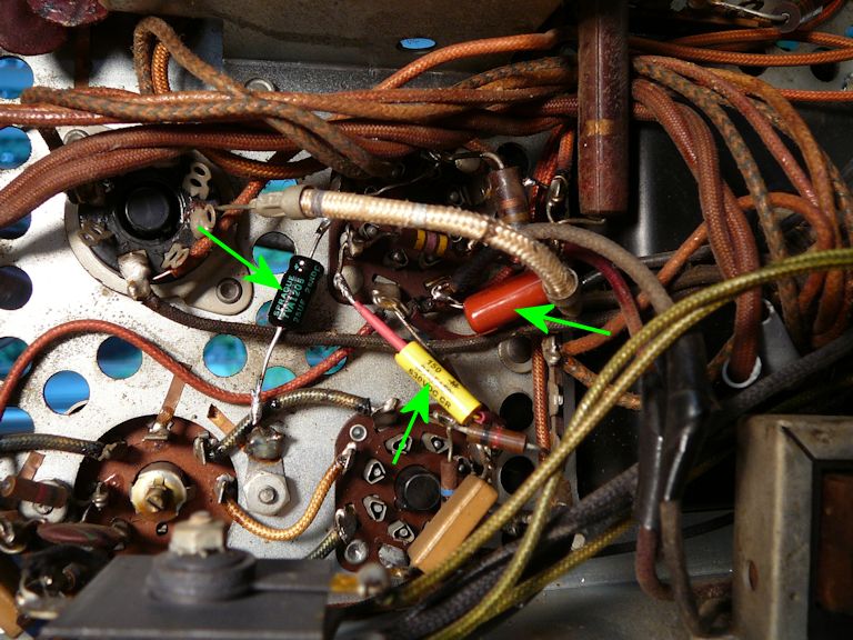
Rather than simply re-flow the old solder on this messy junction, I decided to remove
everything and connect new parts cleanly. This involved replacing the same parts
I had replaced on the other audio IF socket, with one additional capacitor.
This photo shows the transplants installed on V17 (bottom) and V22 (top).

I tried the TV again, and the audio came back. A tweak to the discriminator
transformer made it sound even better. But I could still hear crackling in
the audio, sometimes accompanied by fleeting white hash in the picture.
Tuner Cleaning Redux
Interference in both video and audio suggests a problem farther back in the signal
chain, such as the tuner. Experimenting with the tuner convinced me that it wasn't
making good contacts. Interference appeared when I switched off-channel and back
again, or simply rocked the tuner shaft.
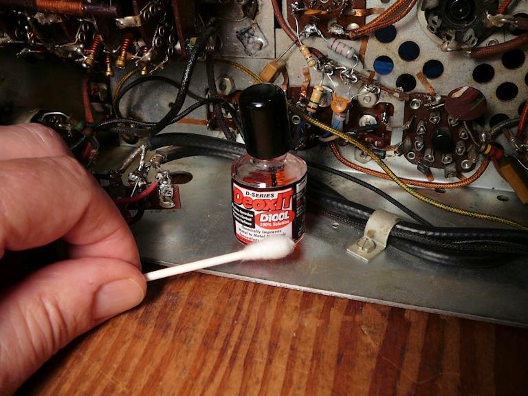
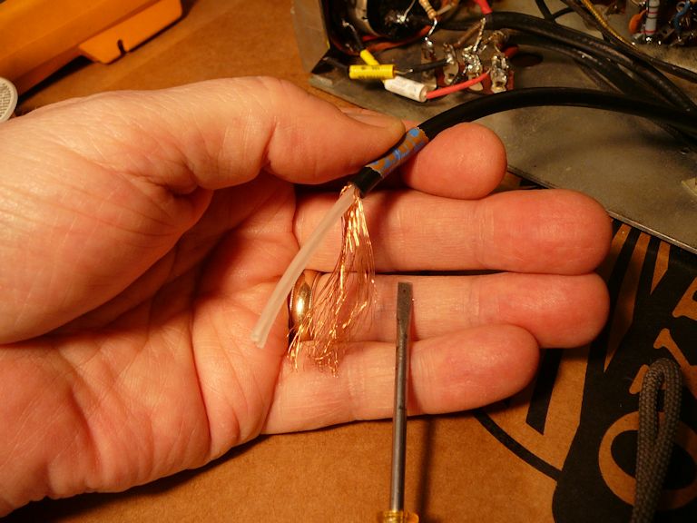
I have seen those symptoms in dirty wafer tuners before, so I decided to clean the
tuner for a third time. I used liquid DeOxit D100L and cotton swabs, rolling the
buds tightly to avoid leaving tiny fibers behind.

It's not easy to reach parts inside this tuner, especially near the front. I held
the wetted swab on each moving contact and then turned the tuner back and forth
through all its channels a few times.

After cleaning each contact, I went back and cleaned each area with isopropyl alcohol,
to avoid leaving excess cleaner on the phenolic wafers. I let the assembly dry overnight
under a low heat lamp.
When I tried the TV the next evening, the tuner changed channels cleanly
and the TV played a long time with no video hash or audio static.
The snap-crackle-pop has been vanquished, at least for now.
One Step Forward and Two Steps Back?
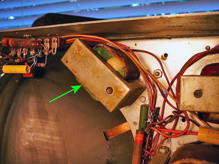
The next time I tried the TV, the picture tube suddenly went dark. A moment later,
the choke in this photo started to sizzle and spew molten wax:

This choke (L20) helps to filter the 360-volt B+ output from the TV's power supply; it is
connected between two electrolytic capacitors (C58, C62):

Fearing that the sizzled choke was ruined, I got a replacement from an eBay vendor
and installed it:

When I tried the set again, I slowly increased the line voltage using my variac, watching its ammeter closely, in case a short circuit was still
present. At roughly 90 volts, when the low-voltage rectifiers began to conduct, the ammeter needle swung
sharply to the right and pegged at the top of its scale, indicating a short in the B+ supply.
I immediately powered down and started to hunt for a cause.
Fixing a Short Circuit in the B+ Line
When faced with a short circuit, you must distinguish between cause and
effect. I first assumed that the sizzling filter choke (L20)
simply failed on its own; but replacing the choke didn't cure the excessive
current drain. The choke's overheating was a symptom, not the
cause, which must be a short circuit somewhere farther down the B+ line.
This TV has two separate low-voltage power supplies: one provides 360 volts
and the second provides 290 volts. This schematic marks
the origin of the 360-volt supply at the downstream side of choke L20:
The 360-volt line leading off to the right connects to several circuits: the 1st video
amplifier; vertical multivibrator; vertical output; horizontal AFC; horizontal size
and linearity; flyback secondary coil and damper tube; and horizontal deflection coil.
This full schematic highlights the 360-volt B+ line in red:

That's a lot of territory to cover, in search of a short circuit.
I began at the 360-volt origin: the junction of choke L20 and capacitor C62.
If electrolytic filter capacitor C62 developed a short, that would ground
the 360-volt line and put L20 under great stress.
Like most of the 810's electrolytics, C62 is contained in a can, and I had replaced
C62 earlier, along with the other electros. By now, the TV had
played happily on the bench for hours and I had previously measured 373
volts at the 360-volt origin point, well within a normal tolerance (±20V). New caps don't fail
often, but anything is possible, so I disconnected C62 and it checked
OK. The short must lie farther down the B+ line.
The B+ circuit branches into multiple nodes, so finding the short meant
disconnecting those nodes at various points and testing many components.
Eventually, aided by a tip from the Antique Radios TV forum, I found the
short in an unexpected place: inside the yoke that holds the
vertical and horizontal deflection coils.
Throughout this testing, I had consistently found a low resistance—roughly 40 ohms—between
the B+ line and ground, wherever I checked. But when I disconnected the vertical deflection
coil's ground connection, the resistance jumped up from about 40 ohms to nearly 80 ohms. Aha!

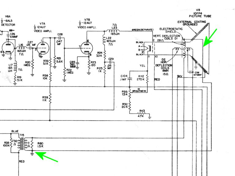
Further testing revealed a very low resistance between the vertical and
horizontal deflection coils, so I removed the yoke for further inspection. The yoke's
barrel is gripped between movable jaws; you can slide it out after freeing the tensioner springs:


The horizontal and vertical deflection coils lie in close physical proximity,
both wrapping around the neck of the picture tube. But they should be electrically
isolated from each other. The horizontal coil connects to B+ voltage via
the damper tube and flyback transformer, whereas one end of the vertical coil
is grounded. If a short should develop between the two coils, that will ground
the B+ line. This schematic shows, in somewhat roundabout fashion,
where the vertical coil connects to ground:

To check for an inter-coil short, I connected my ohmmeter between one terminal
of the horizontal coil and one terminal of the vertical. A normal yoke should
have infinite resistance—no connection—between the two coils.
My yoke measured only a few ohms resistance between the coils.
Somewhere inside, there's an electrical path where there should be none,
likely due to crumbling old insulation.
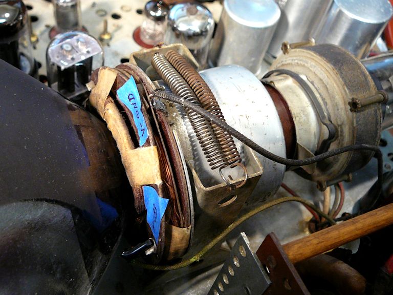
This yoke was not designed to be taken apart. The whole assembly
is glued together very firmly, making it impractical to disassemble the yoke and
repair it or find where the short occurred.
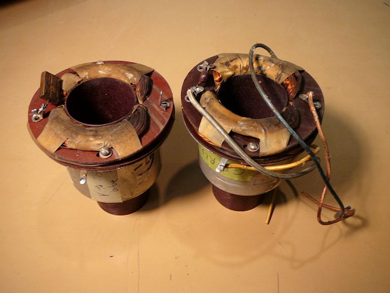
I bought a replacement yoke from the same guy who earlier sold me a replacement choke.
In this photo, my defective yoke is on the left:
I double-checked the new yoke to confirm it had no internal shorts, and
then installed it. The short circuit was repaired and my picture reappeared!


Replacing the yoke took only a few minutes, but I had spent hours in search of the short:
taking measurements, tracing connections, and checking components. In restoring dozens
of vintage TVs, I have never run across a bad yoke, but there's a first time for everything. This
is one lesson I won't forget!
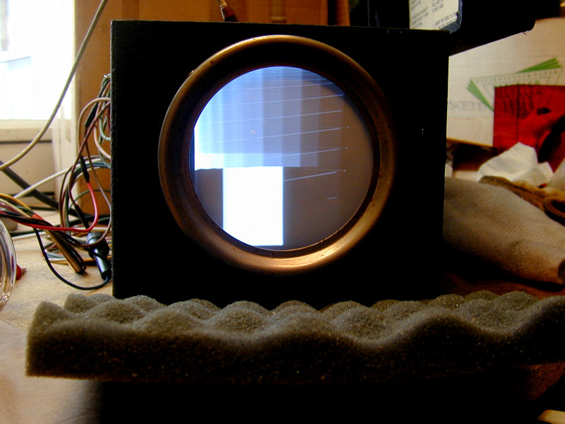
Adding Retrace Blanking
Like many early TVs, the original version of the GE 810 displays slanting
"vertical retrace" lines if you adjust the brightness and contrast controls
beyond a certain point. This photo from another project shows such lines:

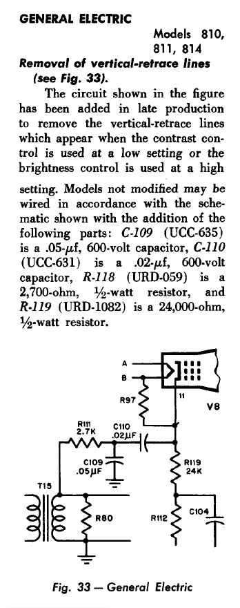
Late in the 810's production, GE added a simple circuit to suppress these lines,
but my early 810 didn't include it. This service note explains how to add
the retrace blanking circuit:

Here, I have laid out the needed parts: two resistors and two capacitors:

Two of the parts can be mounted on an unused terminal near the Brightness and
Contrast controls:


Thanks to retrace blanking, now I can adjust the contrast and brightness to achieve
a very nice picture—with no slanting lines!

I found this service note in Volume 2 of Rider's TV Manufacturer's Receiver Troubles and Cures.
The Receiver Troubles book (in six
volumes) is a good resource to check whenever you restore a vintage TV.
Adjusting Screen Geometry
Now I can adjust the screen geometry, using my Philips PM 5518 TV pattern generator:

Here, the pattern generator is creating a basic crosshatch pattern, overlaid with a circle
pattern. I have adjusted the TV's geometry controls—vertical size and linearity, horizontal size and linearity, and centering—so that everything looks symmetrical and properly
centered.
In the GE 810, the size and linearity controls are electronic adjusters that you screw
in or out while viewing the screen. You center the displayed image on the picture tube by rotating
two circular magnets located on the picture tube's neck.
After the TV is reinstalled in the cabinet, I'll tweak the geometry controls one last
time, so that the edges of the TV image fit the cabinet's screen opening precisely.
Cabinet Restoration
With the electronics under control, I turned to the cabinet and its brass trim. The wood finish
is presentable, but the brass is badly worn and corroded in spots.
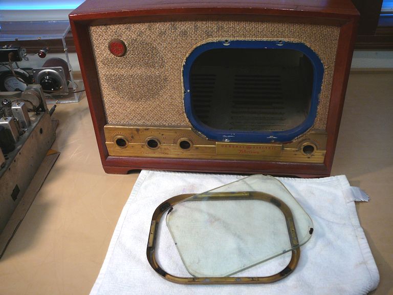
Disassembling the cabinet and trim means removing several nuts and wood screws from inside:

Removing the brass bezel frees the safety glass:

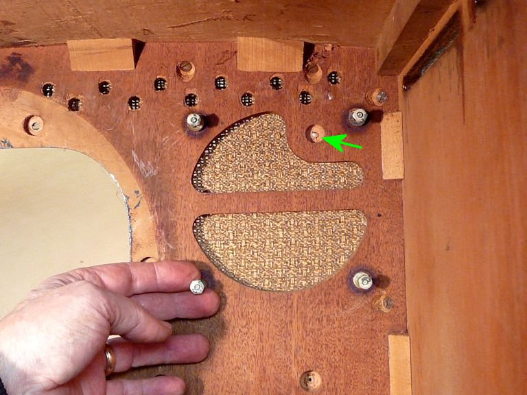
In the next photo, I have removed the speaker and the little round GE emblem; a green arrow
points to the spot where the emblem's nut was fastened. I temporarily put the speaker
mounting nuts back on their screws, to avoid losing them.

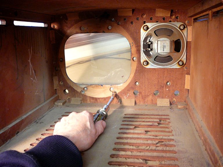
The big brass faceplate is fastened to the grille with nuts on the inside, and its edges are
clamped in place by the wooden frame in front. In addition to removing the nuts, you need to remove several wood screws to release the frame.

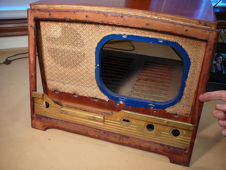
In the next photo, I have removed (and reversed) the frame and I'm ready to pull the faceplate,
which fits into the recessed frame edge. A few thin brads, like the one
by my finger, help to position the frame precisely against the cabinet front. Don't
remove the brads; they'll help you align the frame when reinstalling it.

The previous photo shows that a prior owner repainted the edge of the cabinet's screen opening—normally, a pale blue-green—in a garish dark blue color. What was he
thinking?? I'll repaint that edge later.
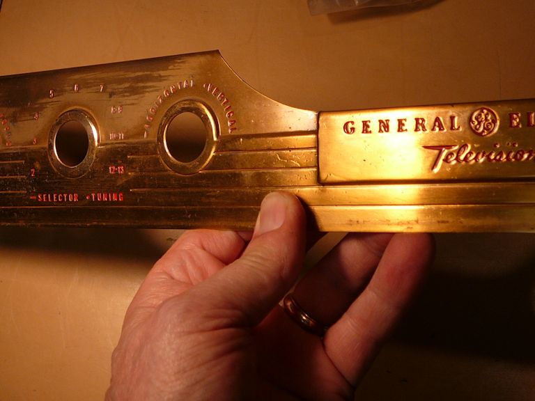
Restoring the Brass Trim
I'll need to strip the big brass faceplate, which is weathered and corroded in the usual
wear areas. Where the original lacquer coating remains, it is yellowed and sloppy.
Look at the hairs and dirt captured in the old lacquer near my thumb:

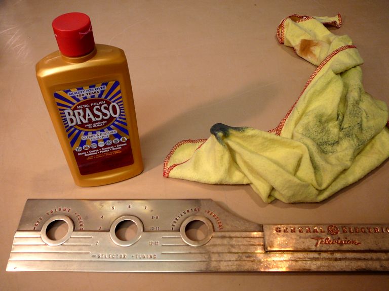
In the next photo, I have stripped off the old lacquer with oven cleaner and begun
to polish the faceplate with Brasso. (You can polish brass with just about any sort of metal
polish.) This looks ugly, but don't panic—the piece will look good after I finish polishing and then re-lacquer it.

This faceplate is solid brass, so you can polish it aggressively without danger of
scrubbing through thin plating.
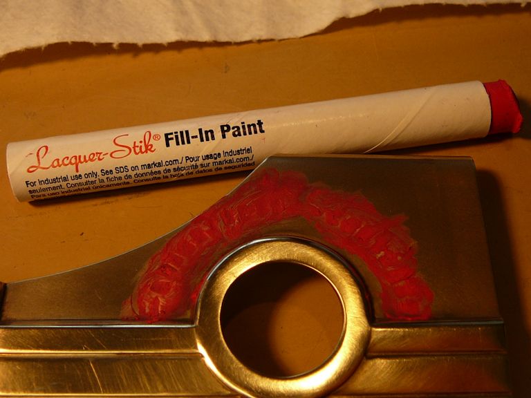
Stripping and polishing removed some of the lettering, which I'll restore it with a red
Lacquer-Stik:

I washed the entire piece with isopropyl alcohol to remove any stripping residue. After the alcohol
dried, I rubbed the crayon-like lacquer material into the incised lettering and then buffed away
the excess with paper toweling.


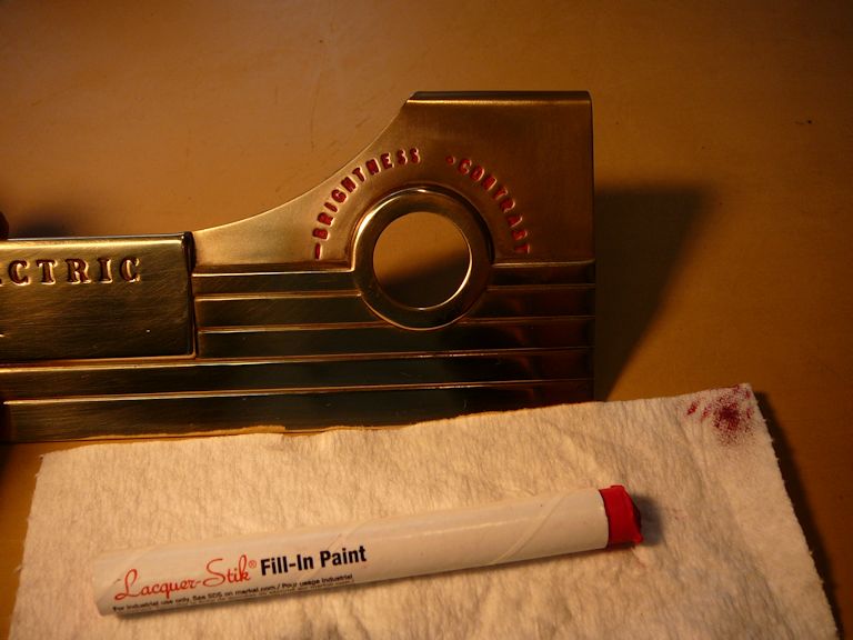
After removing the excess color, I re-washed the surrounding areas with isopropyl alcohol and
Q-tips. When you're prepping brass for lacquer, the metal must be clean, clean, clean!
I used the same methods to strip and polish the small round GE
emblem and the rectangular screen bezel. Then I sprayed all the trim pieces with a few coats of lacquer:
If you need to restore incised lettering and you can live with a limited color
palette (red, black, or white), lacquer sticks are easier and faster than
laboriously filling each letter with a tiny paintbrush. The stick
material is stable and you can lacquer over it immediately.
Cabinet Refinishing
The cabinet wood is in nice shape; it only needs a light refresher. After
cleaning the wood with paint thinner, I applied a thin coat of mahogany stain and
immediately rubbed off the excess. That concealed the little scuffs without changing the
color or darkening it too much. I let the stain dry overnight, buffed the wood again,
and sprayed on a few coats of clear lacquer to protect the finish and add
some depth.
Let's reassemble the cabinet with all the brass parts and safety glass:

Everything looks good, except for that garish blue border around the
screen opening. I had hoped the blue wouldn't be very noticeable when reassembled
behind the brass bezel, but it sticks out like a sore (and incorrect!) thumb. I
repainted the border with acrylic paint mixed in a pale blue-green.

Are We Home Yet, Daddy?
After reinstalling the chassis, I gave the TV a nice, long bench test.
It looked and sounded great!
Replacing the Power/Volume Control
My happiness lasted for a couple of days . . . until the Power/Volume switch conked out.
Unable to turn the set on, I reluctantly pulled the chassis to investigate.
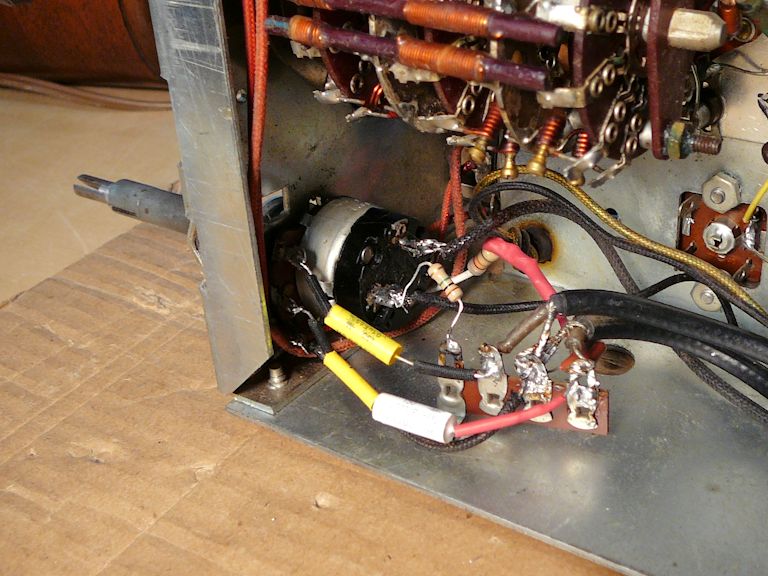
As in most radios and TVs, the Power/Volume control in this set lets you turn
the set on and adjust the volume, using a single knob. But the installation is
complicated because the TV has a second control (Focus) mounted
on the same shaft. Concentric knobs let you operate the two controls
independently.
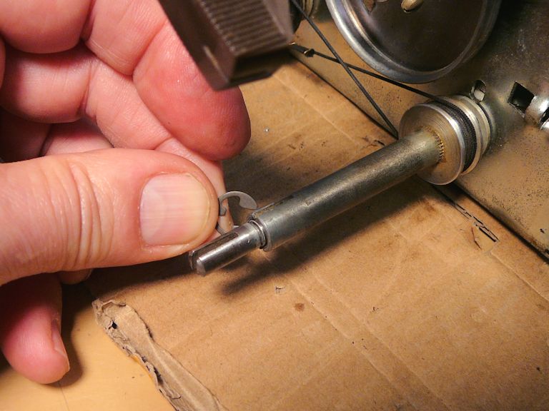
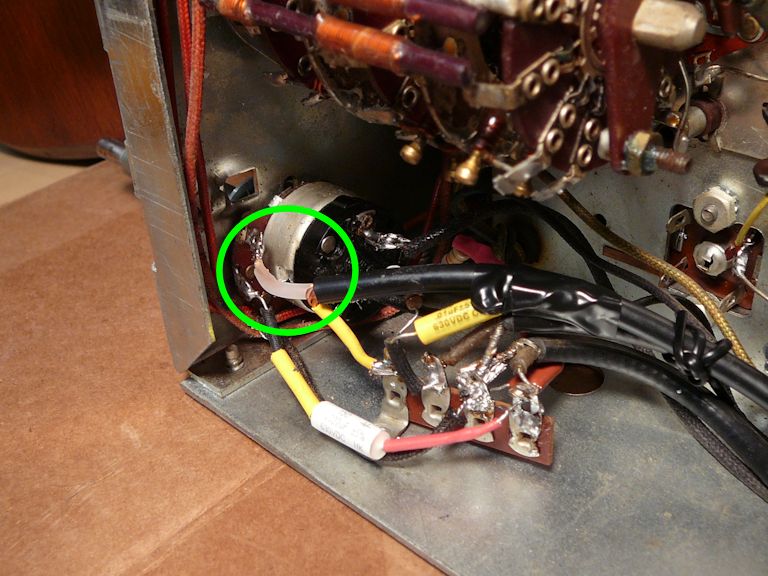
In this photo, the Focus control shaft is the hollow one
(marked with a green arrow) that uses a string and pulley to drive the Focus
potentiometer up above. The shaft for the Power/Volume control runs inside that
hollow shaft.

Removing this control is a little tricky. The hollow Focus shaft is held on the
inner shaft with a small C-clip.

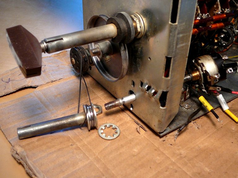
After you remove the C-clip, you can unscrew the nut
holding the control case on the chassis. That frees the shafts from each other, but
you still need to unsolder the small components wired to the control's terminals
inside the chassis. After those connections are undone, you can carefully slide the
control backward through the hole in the chassis. This leaves the hollow shaft still
attached to the chassis by its pulley string.

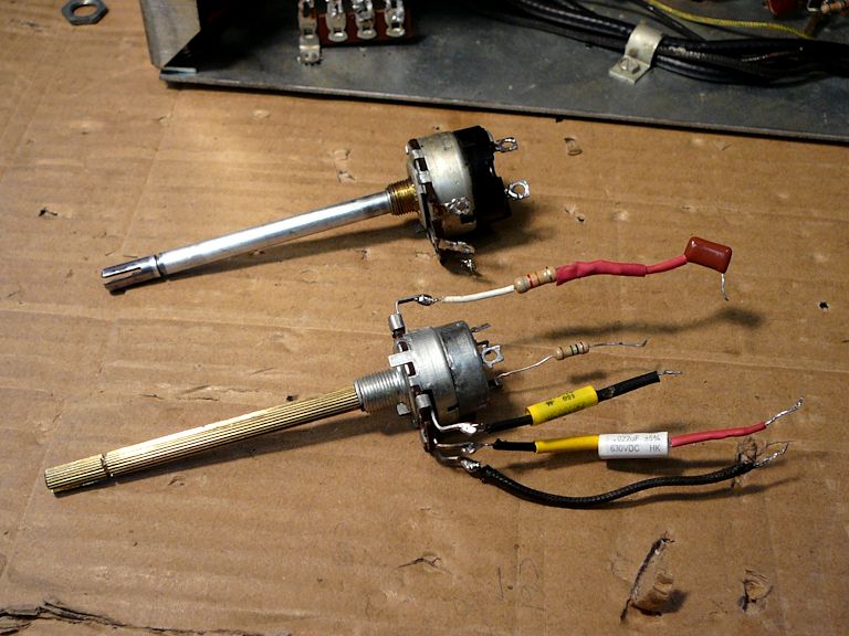
Now you can mount the small components on the new control and reinstall it.


I actually went through this process twice. The first time, I installed my original
control which I had sent out to be rebuilt. When the rebuilt control failed after a short
time, I sent out for a scratch-built control made from new parts. That one is
still working reliably, knock on wood.
Injecting Audio and Video
After I used the TV for a while, the tuner relapsed yet again. Grr! Despite cleaning the
tuner several times with various materials and methods, it simply wasn't reliable.
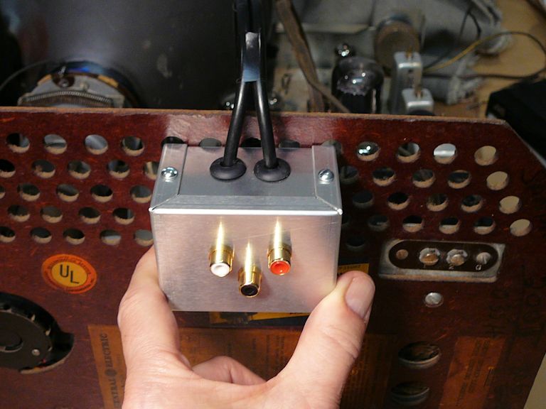
The solution is to bypass the TV's front end and inject audio/video signals directly at
the output circuits.
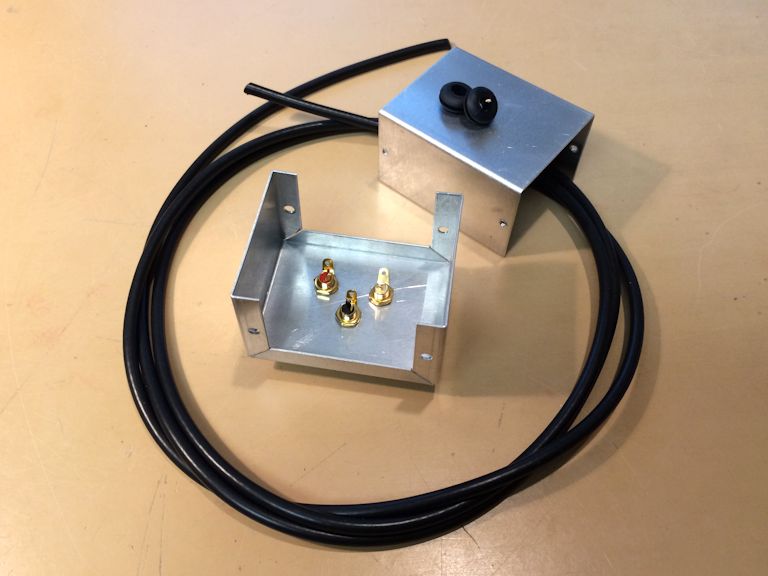
The article Direct Audio/Video Adapter for Vintage TVs
outlines the general process and shows how I built an A/V adapter for my
Admiral 24C15 television. I have also installed
such adapters on a couple of other sets (see
Emerson 609 and
RCA CT-100).
Installing the adapter was straightforward; refer to the previous article
for details of this process.


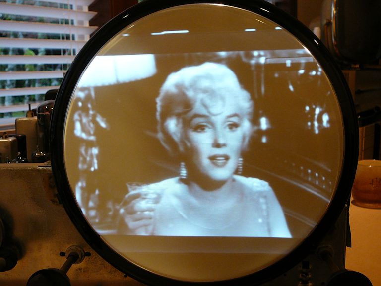
The results were gratifying—clear sound and a beautiful picture.
Final Thoughts
This was an enjoyable project, although it involved some odd
problems. I have never found a shorted deflection coil before.
And tube sockets don't burn up very often, either.
The 810 is one of the most attractive 1940s tabletop TVs,
and now my restored set performs like new. As with other GE products
of the day, its construction shows evidence of cost cutting. But the
classy little 810 is satisfying to watch when firing on all cylinders.
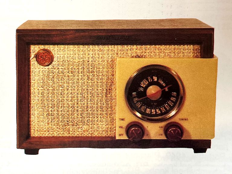
Since finishing the 810 television, I have been hunting for a GE Model 212 AM/FM
radio from 1948, whose appearance makes it an ideal companion:

The family resemblance is striking! Notice the big fabric panel with the
red-and-gold GE medallion in the upper left corner. If you have a GE 212 radio for sale, kindly
contact me. Perhaps we can make a deal!
|