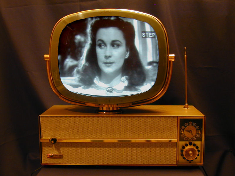
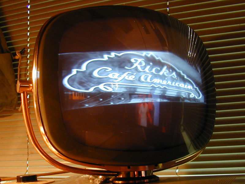
Philco Model H3412L Predicta Television (1959)


This tabletop Philco Predicta TV was known as the Siesta. With
a compact cabinet and signature stand-alone screen, it includes a clock timer
that can turn the television on and off. Here's my Siesta after restoration:
Description
In 1959, Philco introduced three 17-inch tabletop Predictas, called the Siesta, Princess, and Debutante.
The Siesta, with a clock timer, was the top model. The Princess was the same TV minus the
clock. The Debutante, as the name suggests, was an entry-level set; it had a cloth grille and its
screen lacked the big gold supporting arms found on other Predictas.
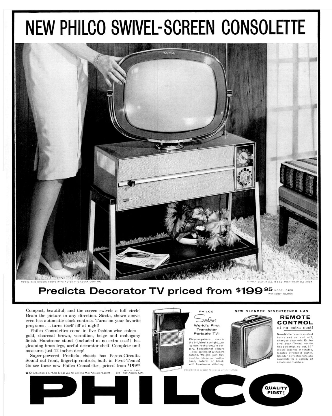
The Siesta was offered in five colors: gold, charcoal brown, vermilion red,
beige, and mahogany. Mine is a gold model H3412L, with the 10L43 chassis that was shared with 21-inch
Predicta tabletops. A magazine ad from December, 1959 shows it with the Consolette stand:
Like many manufacturers, Philco made up flashy names for their features.
In this ad, their printed circuit boards were Perma-Circuits and the pivoting
rod antenna—a commonplace item—was dubbed the Pivot-Tenna.
In a footnote, the ad mentions Philco's sponsorship of an upcoming Miss America
pageant. My Philco Miss America article
has more information about that long-running ad campaign.
The next ad, from January, 1960, touts Philco's new "cool chassis" design, claiming that it
provided "43% longer TV life" than older designs.
The coolness of the Philco cool chassis was debatable,
but we'll come to that later.
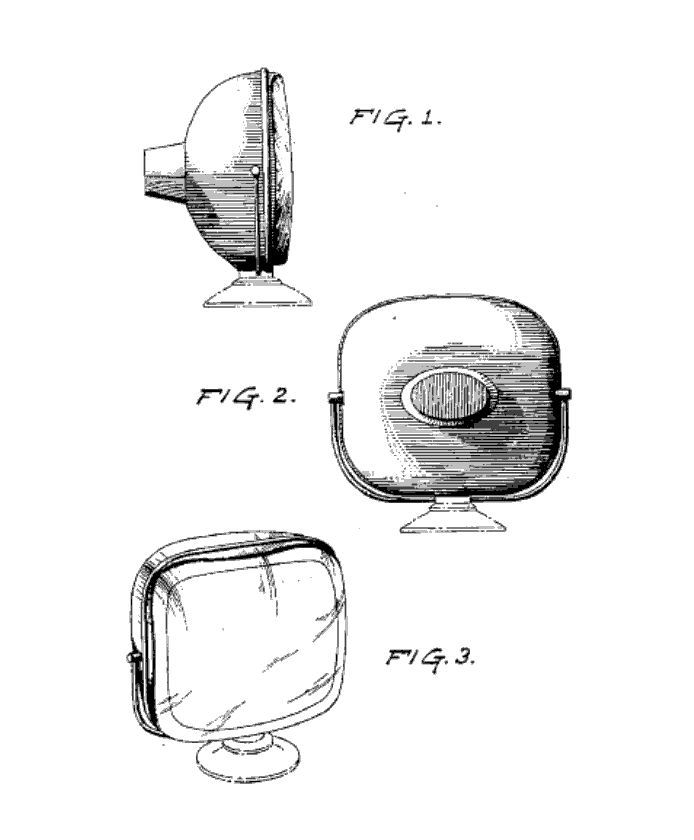
Philco took out two patents for the Predicta tabletop design. The first
drawing, for patent
186629,
depicts the famous screen. The second, for patent
183779,
shows a "Predicta that never was." While the general profile
was repeated in the 17-inch and 21-inch tabletops, the knob arrangement
was changed before Predictas made it to market.
The Predicta's exterior is flashy, but its electronic design is conventional and rather spartan.
It lacks DC restoration and various controls for focus, centering,
horizontal drive, and so on, which were found on better quality televisions.
Adjusting the focus involves moving a lead from one terminal to another on
the printed circuit board—not a user-friendly arrangement.
One welcome sign of quality is a power transformer. Some other Predictas,
such as my pedestal
4654 console, use a cheaper series-string power supply.
Solid-state rectifiers are used in the low voltage power supply
(early versions of the 10L43 chassis use a rectifier tube) and
silicon diodes are employed in the horizontal phase comparator.
Like many TVs and radios of the day, the
Siesta has several "couplates" (aka networks), an early form of
integrated circuit with several capacitors and resistors
in a flat package about the size of a matchbook. These will also be
examined later.
The H3412L uses 15 tubes, including the 17DRP4 (or 17DAP4) picture tube:
| Tube |
Type |
Function |
| S1T |
6X8 |
Oscillator / Mixer |
| S2T |
6X8 |
RF amplifier |
| S1 |
6AM8A |
3rd video IF amp/Video det. |
| S2 |
6DE6 |
2nd video IF amplifier |
| S3 |
6DE6 |
1st video IF amplifier |
| S4 |
6BQ5 |
Audio output |
| S5 |
6DR7 |
Vert. oscillator / Vert. output |
| S6 |
6CS6 |
Audio discriminator |
| S7 |
6EA8 |
Sound IF amp. / Noise inv. |
| S8 |
6CG7 |
Horizontal multivibrator |
| S9 |
6AW8A |
Video output / Sync separator |
| S10 |
6DA4 |
Damper |
| S11 |
6DQ6A |
Horizontal output |
| S12 |
1B3GT |
High voltage rectifier |
| |
17DRP4 |
Picture tube |
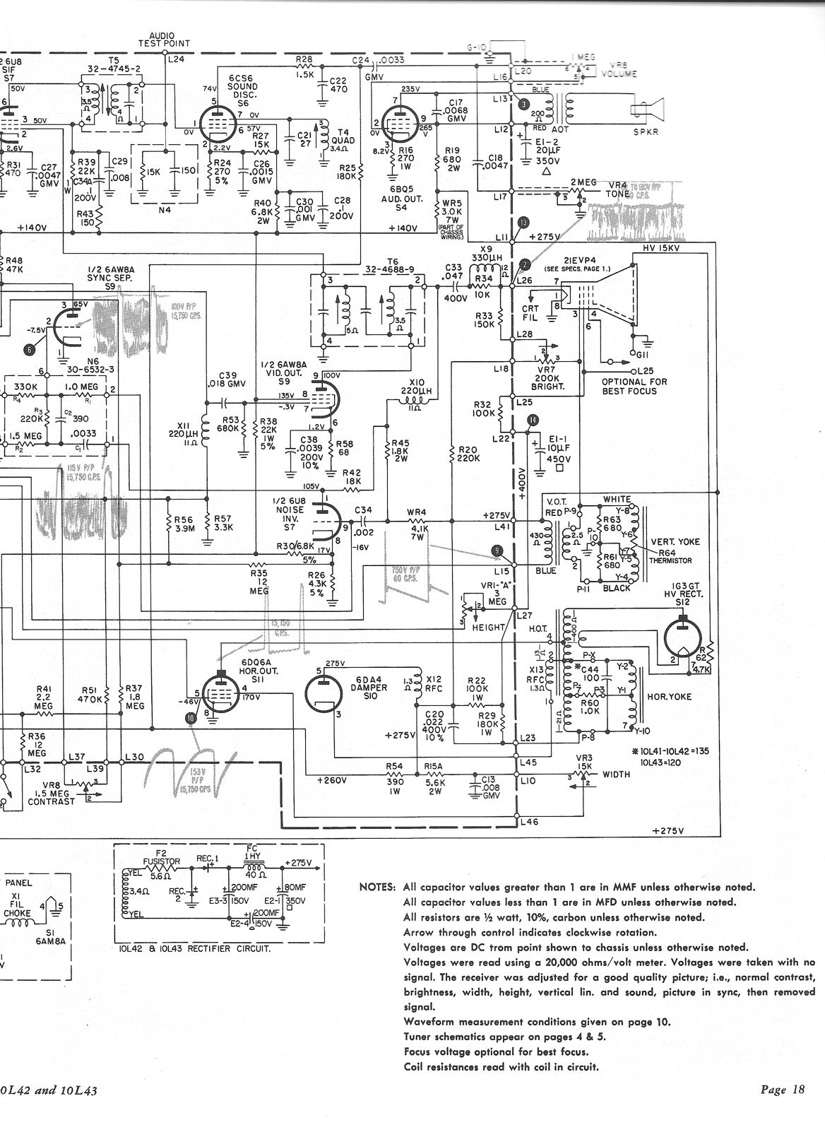
This Predicta's service manual is found in Sams
Set 466, Folder 1. Midway through this project, I also got an original
Philco service manual. Below are two pages containing the Philco schematic.
To save the files on your computer, right-click on the icon and then choose Save Picture As:
If you restore a Predicta, I recommend using both the Sams and Philco manuals.
This article refers to components by their Philco part numbers, which
are printed on the circuit boards.
Finding a Predicta Siesta
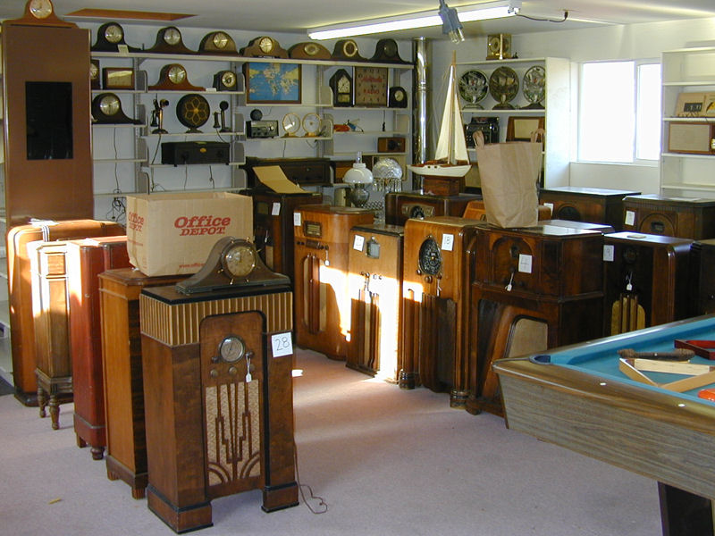
Although I bought this Predicta in 2012, I first saw it 1998,
when reporting on a tour of a fellow collector's
premises. That visit was recorded in A Visit to Radio Heaven
and the Predicta was seen on a shelf in this photo:
I wasn't particularly interested in TVs at the time, but I never forgot
the sight of that one distinctive television amidst hundreds of radios.
Nearly 14 years later, I learned that the collector had passed away and
his collection was being sold. I visited his son to see what was available.
Off to the side, in a room full of radios, sat the same Predicta,
looking just as I remembered.


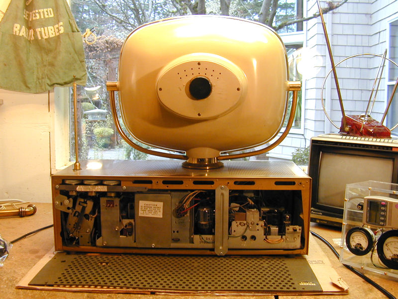
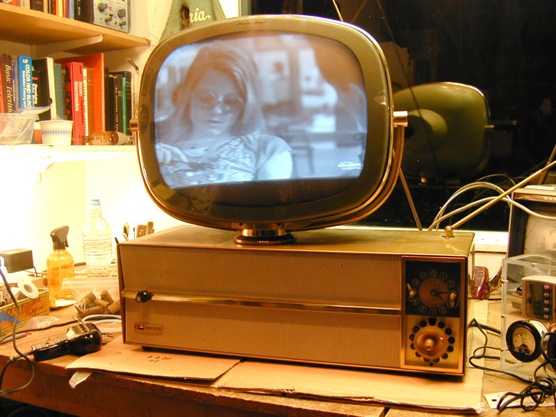
First Look
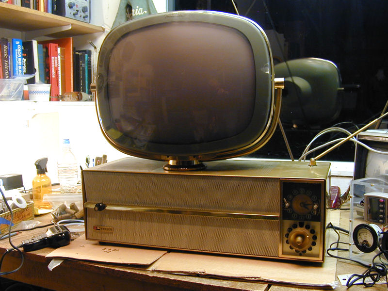
We made a bargain and the Predicta followed me home. Here are the first photos
of the set in my workshop:

As you can see, the television is in nice cosmetic shape. The grille and gold paintwork
are fine, the plastic parts are intact, and the back cover and knobs
are present.
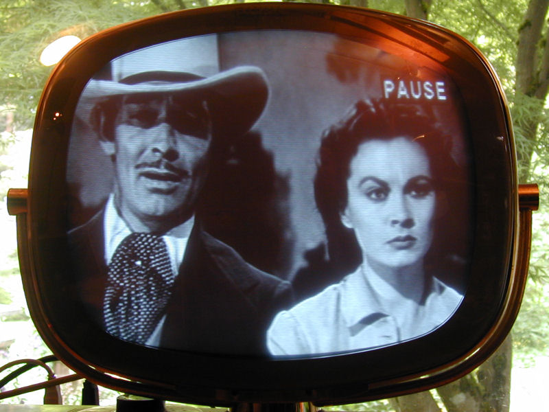
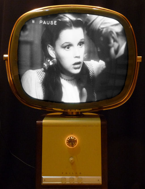
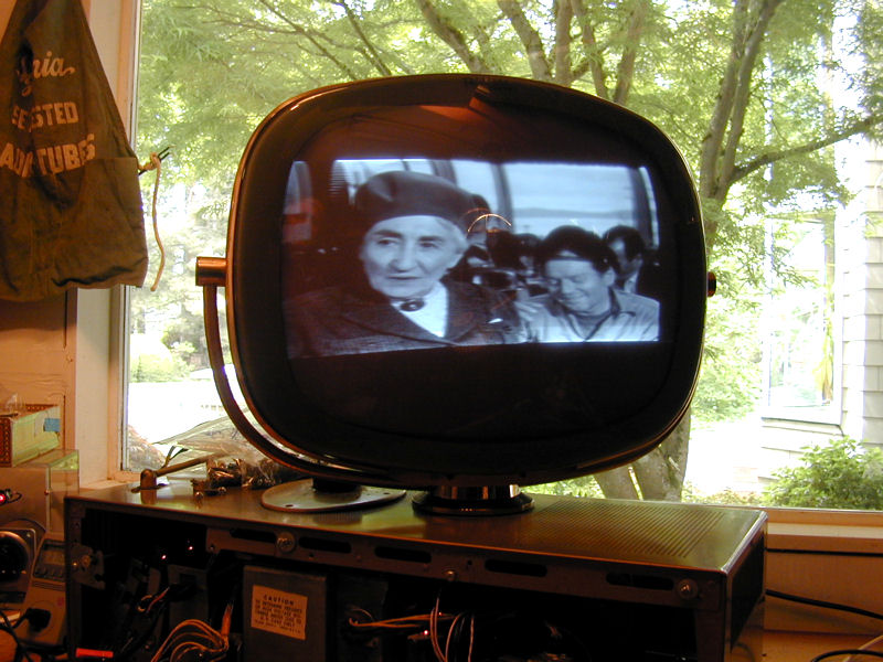
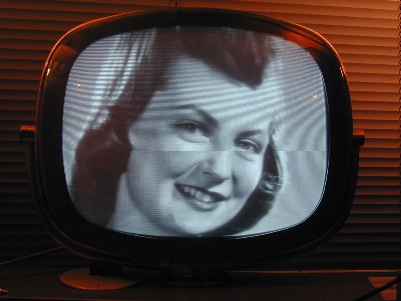
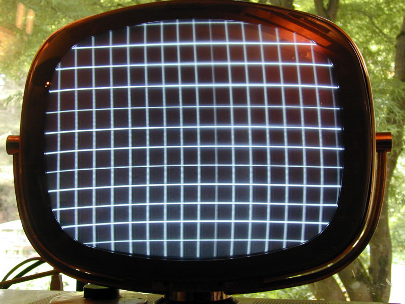
After making a few checks, I slowly powered up the TV using my metered variac
and was rewarded with a picture!
That's Jodie Foster in Taxi Driver, which happened to be playing on cable at the time.
The TV is receiving the signal on its built-in rod antenna, broadcast from my
home TV transmitter on the other side of the house.
The height was insufficient and the yoke slightly tilted, but the Predicta was basically functional.
I powered it down and set the TV aside for a few months until I finished other projects.
Replacement Picture Tube
The Predicta design requires a picture tube with a very short neck.
It's common for picture tubes to be replaced, and when that occurred
with Predictas, sometimes a tube with a slightly longer neck was used.
That's what was done with my Siesta. In the previous rear view,
you can see a small brown cap on the rear cover. The serviceman cut a little
hole in the cover to accommodate the longer neck and added a cap to
protect it.
The original 17DRP4 CRT has a 2.68-volt filament. Some of the compatible
replacement tubes take a 6.3-volt filament, and when those were installed,
a simple modification was made to supply the higher voltage.
Before you test a Predicta picture tube, make sure you know which
type of CRT it has. You don't want to damage a 2.68-volt tube by
powering it at 6.3 volts.
Restoration
This is my second Predicta television. The first was a 21-inch model 4654
in the pedestal console cabinet, which I restored about a dozen years ago:
My first Predicta restoration was quite a learning experience,
which you can read about in that article.
Disassembly
The first step was to remove the chassis and find out what I had. Removal
is simple, requiring only a screwdriver, nut driver, and pliers.
There are two approaches to disassembling a tabletop Predicta. If you have a jumbo
workbench, you can remove everything from the cabinet, lay the picture tube on
a cushion, and then reconnect all of the parts whenever you need to power up the TV.
I chose to remove only the chassis, leaving the tuner, clock, and picture tube in
the cabinet. This saves space and reduces the risk of damaging the heavy and awkward picture
tube, but you need to reinstall the chassis to test the TV under power.
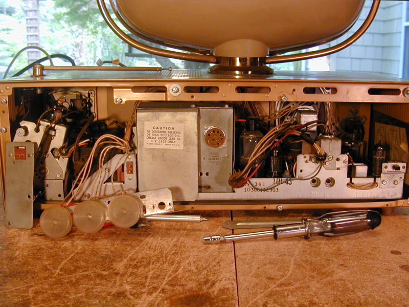
In the next photo, after removing the back cover, I have unfastened the little rear panel
that holds three thumbwheel controls for brightness, vertical hold, and horizontal hold.
I also unplugged power cords for the TV and clock, and cables for the yoke, tuner power,
and picture tube.

At this stage, you can slide the chassis back a couple of inches to unplug more things.
Reaching inside, over the main circuit board, unplug two speaker leads
from the audio output transformer and one wire from the Video output pin on
the board.
After removing one screw, you can lift up the HV cage lid, remove the 1B3GT HV rectifier
tube, and then unplug the second anode lead for the picture tube. It simply slides into
a hole in the 1B3GT socket.

If you have recently played the TV, use a clip lead to ground that HV lead to the chassis
before you touch it. This discharges any latent charge held by the picture tube and
prevents you from receiving a painful (although not fatal) shock.
Also in the previous view, you can see a green wire coming up from the main printed
circuit board and grounding behind a screw on the chassis. Predictas are notorious
for bad contacts on the main circuit board, and evidently this was one serviceman's
solution. The photo also shows the two speaker leads that were unplugged from
the audio output transformer.
Peering into the cabinet at the left, you can see the cloth-covered shielded cable
that brings the signal from the tuner to the IF (intermediate frequency) section.
Unplug this from its phono style jack.

Finally, reaching in with a nut driver, dismount the power/volume control and
gain control after removing two nuts inside the front panel.
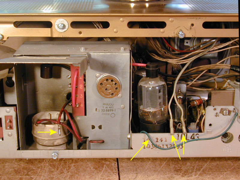
The chassis has been freed:
In the photo, I numbered the leads and cables that connect the chassis to
the rest of the TV:
- AC power to clock
- Power to tuner
- AC power to chassis
- HV to picture tube
- Picture tube
- Video
- Speaker
- Yoke
- Tuner signal to IF
Notice that the three thumbwheel controls and the dual front control stay with
the chassis, connected by long leads. When moving the chassis
around the workbench, be careful not to twist or yank those leads.
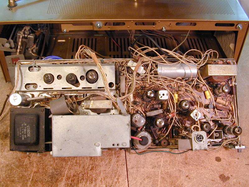
Next, an overhead view shows the basic layout. At lower left is the power transformer. Next
to it is the HV cage, which contains the HV rectifier tube and flyback transformer. At
upper left is the IF section with its three tubes. To the right are the main circuit board,
a large can capacitor, and the vertical output transformer at upper right.

The main board looked in decent shape, although the area around the horizontal
tubes (lower left of the board) was coated with dark oily stuff. Tabletop Predictas
create lots of heat in a small space and it's common to see some evidence of overheating
near hot tubes.
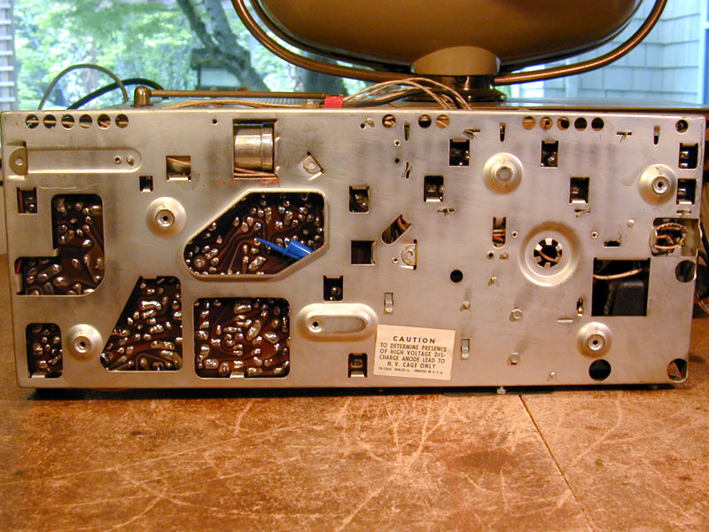
Turning the chassis over, you can see why the Predicta was cursed by generations
of repairmen. Although there are a few cutouts in the chassis frame, much of the
main board's underside is inaccessible:

A blue cap from an ink pen was wedged firmly between the board and the chassis.
Perhaps it was accidentally swept into that spot when someone reinstalled the board, or
a repairman intentionally stuck it there for some reason. Let's hope this is not a caveman
"repair" for a problem such as a cracked trace or intermittent
ground contact.
How Cool Is The "Cool Chassis?"
When you look closely above and below the Predicta chassis, it's evident that Philco's
"cool chassis" tag was a bit of a misnomer. Yes, there are vent holes
underneath and on the edges, but the entire perimeter of the main circuit
board is crammed full of connecting leads, so there is less
through-chassis ventilation than suggested in the dramatic magazine ad.
While the metal of a conventional chassis conducts and distributes heat,
the synthetic circuit board material is more of an insulator. It also can be damaged
by heat over time.
Philco did a reasonable job of ventilating its tightly-packed cabinet, but it's
still far more cramped than the roomy console cabinets of most older TVs.
Size alone means that these TVs inevitably run hot. Some present-day
Predicta owners install little muffin fans to combat overheating, although
I personally find the fan noise distracting.
Cleaning and Inspection
I start every project by cleaning and testing components. Every tube is removed and
checked on my tube tester, and then I clean its pins and every hole in its socket.
As often happens, all of the tubes tested good. Since the TV worked, at
least marginally, that wasn't a huge surprise.
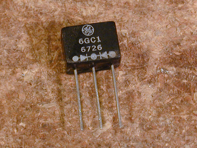
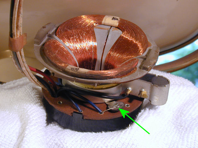
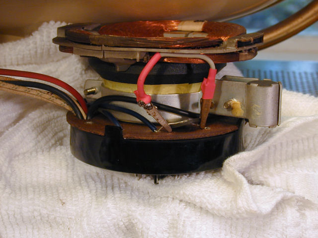
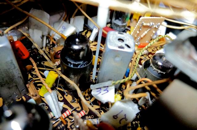
Don't overlook this little item when cleaning. As the marking indicates,
it's a dual diode used in the horizontal comparator. I removed it to make sure its pins are clean,
like any other plug-in component.

I inspected everything else under strong light,
looking for trouble signs like burned components, broken leads, or blobs
of leftover solder from sloppy repairs.
This Predicta looked unmolested, with signs of minor
service in the past. On the main board, three capacitors had been replaced by
snipping the original leads above the board and soldering
new caps to the stubs. Two of the replacement caps were the relatively
modern yellow type. Perhaps the prior owner did a minimal
make-it-play service within the last 20 years.
I normally prefer a neater replacement method, but during the Predicta's
normal service life, "pigtailing" above the board would have been
reasonable to address minor problems. Unwiring the main board circuit board
merely to make things neater would have added a lot to the repairman's bill.
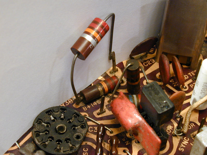
I'm less enthusiastic about this repair. See how the serviceman
piggybacked a new resistor in parallel with the old one, rather than replacing it.

This is a dropping resistor in the noise inverter bias circuit, specified as
22K ohms with a 5% (more precise than usual) tolerance. No doubt the original
resistor's value drifted upward with age. Wiring another resistor in parallel
would somewhat reduce the resistance, but I doubt whether this quickie combination fell
within 5% of the needed value. When I remove the main board for recapping, I'll
redo this the right way.
I then cleaned the entire chassis using isopropyl alcohol, paper towels, and a soft brush.
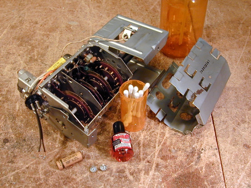
Next, I took out the tuner mechanism and removed its shield, which gives access to
the contacts inside.

Most old TV tuners benefit from an internal cleaning to remove grime and
oxidation from their contacts, but when doing so, follow the motto, "less is more."
Avoid spraying cleaner all over the place and don't use anything abrasive, which
can destroy the precious metal plating on contact surfaces. I apply liquid
DeOxit with a Q-tip, rubbing the contacts and operating the tuner from time to time.
While the tuner was out, I replaced a paper capacitor on its top. You ordinarily
don't replace any resistors or capacitors inside a tuner, however. Its internal parts are
extremely reliable and replacing any of them may force a needless and difficult realignment.
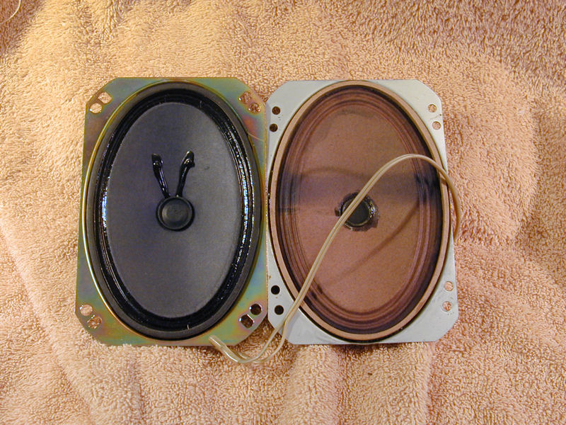
Replacing the Speaker
The TV's audio was faint and much distorted, and a quick speaker swap revealed the cause.
Connected to another source, the Philco speaker sounded awful, while a test speaker connected
to the TV sounded great. I happened to have on hand a new speaker that fit, so
I popped it in, reusing the leads that plug into the audio output transformer.

Problem solved!
The old speaker looks fine on the outside, but something inside (perhaps the voice coil?) needs
help. Maybe on some rainy day I'll see whether it's repairable.
Replacing Electrolytic Capacitors
The next, most labor-intensive, phase was capacitor replacement.
The Predicta chassis is cramped, so I restuffed all
of the electrolytic cans, rather than install
new caps outside of them. In many TVs and radios, you can install
replacements under the chassis, but this chassis has no
"underneath" in the usual sense.
The electrolytics are mounted outside the main circuit board, so you can
replace them before or after removing the board.
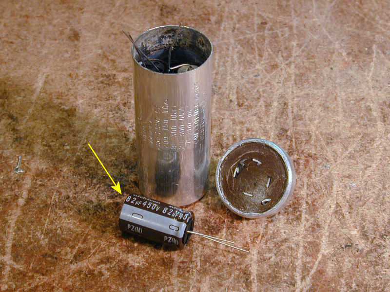
The E2 electrolytic can was slightly tricky. It contains four caps, but only
three of my replacements will fit inside. Here, I have left the 82-mfd
cap outside the emptied can:

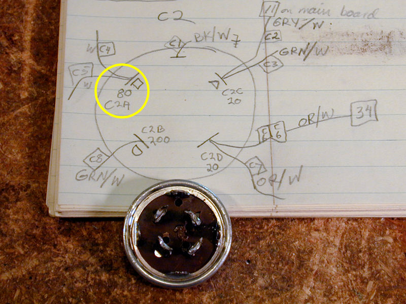
I drilled holes in the can base for the new capacitor leads and
drew a little diagram to help reconnect everything. (At this early
stage of the project, I was using Sams part numbers rather
than Philco part numbers.) Numbered
tags are attached to the disconnected leads.

After restuffing E2, the can is reinstalled and the 82-mfd cap is snuggled next
to the can's terminals.

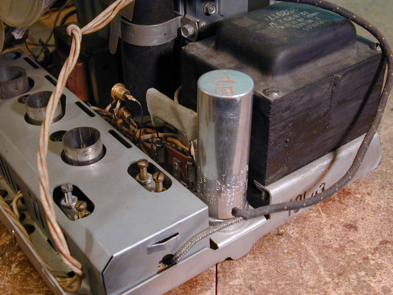
Three new caps fit easily inside the E1 can. In the first photo, the rebuilt
unit has been rewired and remounted on the chassis. Then the can is glued back on.


Don't overlook capacitor C41, the AC line filter hidden behind the
power terminal. It should be replaced with a modern Class X
safety capacitor.


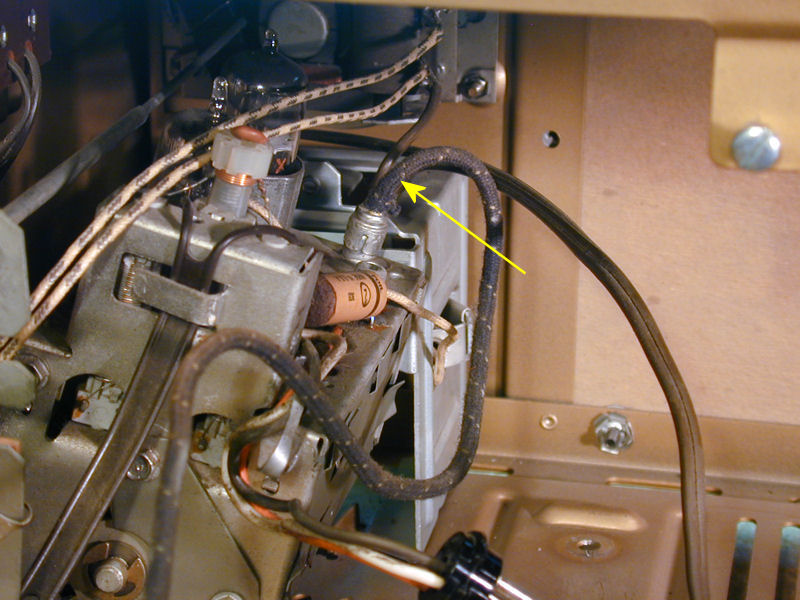
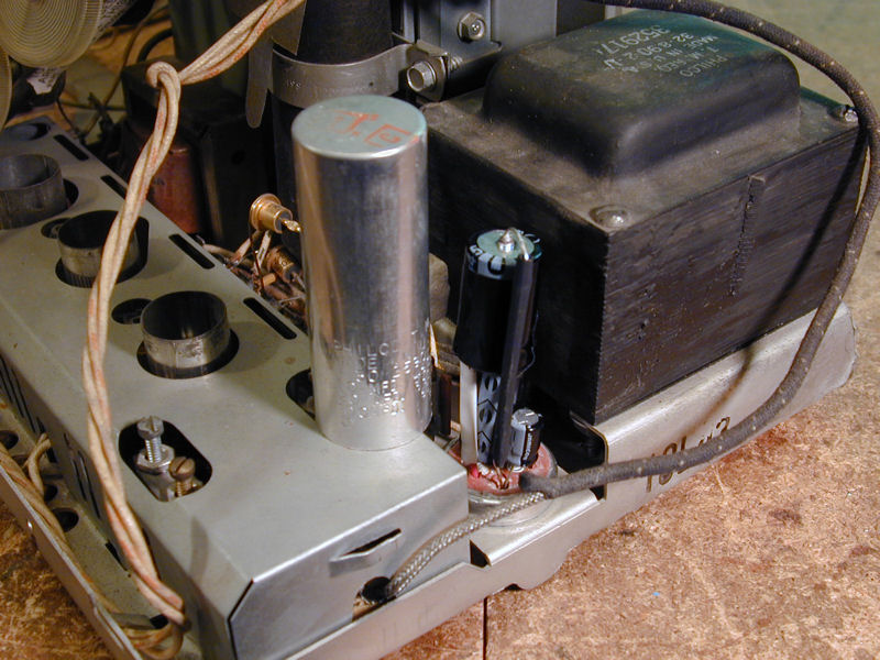
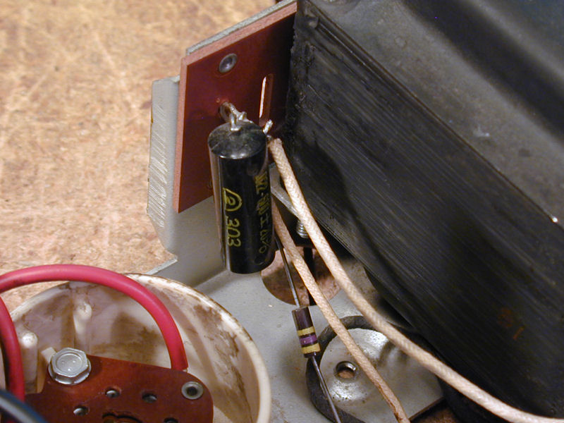
Another slightly hidden cap is C42, the B+ decoupling capacitor for video IF.
It is mounted on a terminal strip just outside the main circuit board. The arrow
points to my replacement; the original was a large "black beauty"
molded paper type.

Servicing the Main Circuit Board
It's possible to replace some components on the main circuit board
using the "snip and pigtail" method from above, but
a thorough restoration requires removing the board.
As with my other Predicta, I unwrapped the leads from the board
lugs, labeled each lead with a tag made of tape, drew a diagram
showing all of the connections, and unmounted a few parts, such
as the range switch and picture tube cable socket, to facilitate
removal.
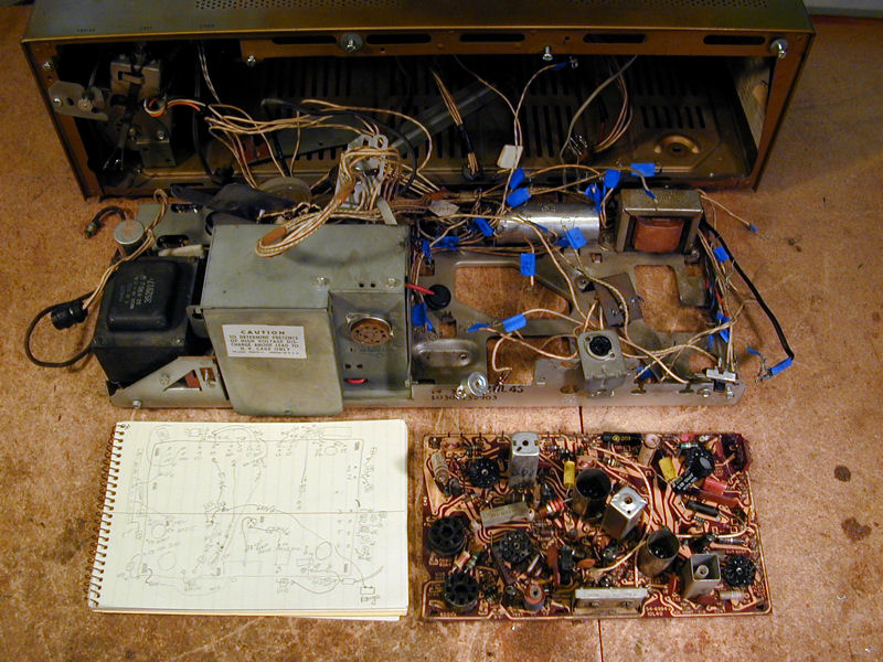
In the next photo, the board has been removed and placed next to
my diagram. Blue tags identify the connecting leads that remain
with the chassis.
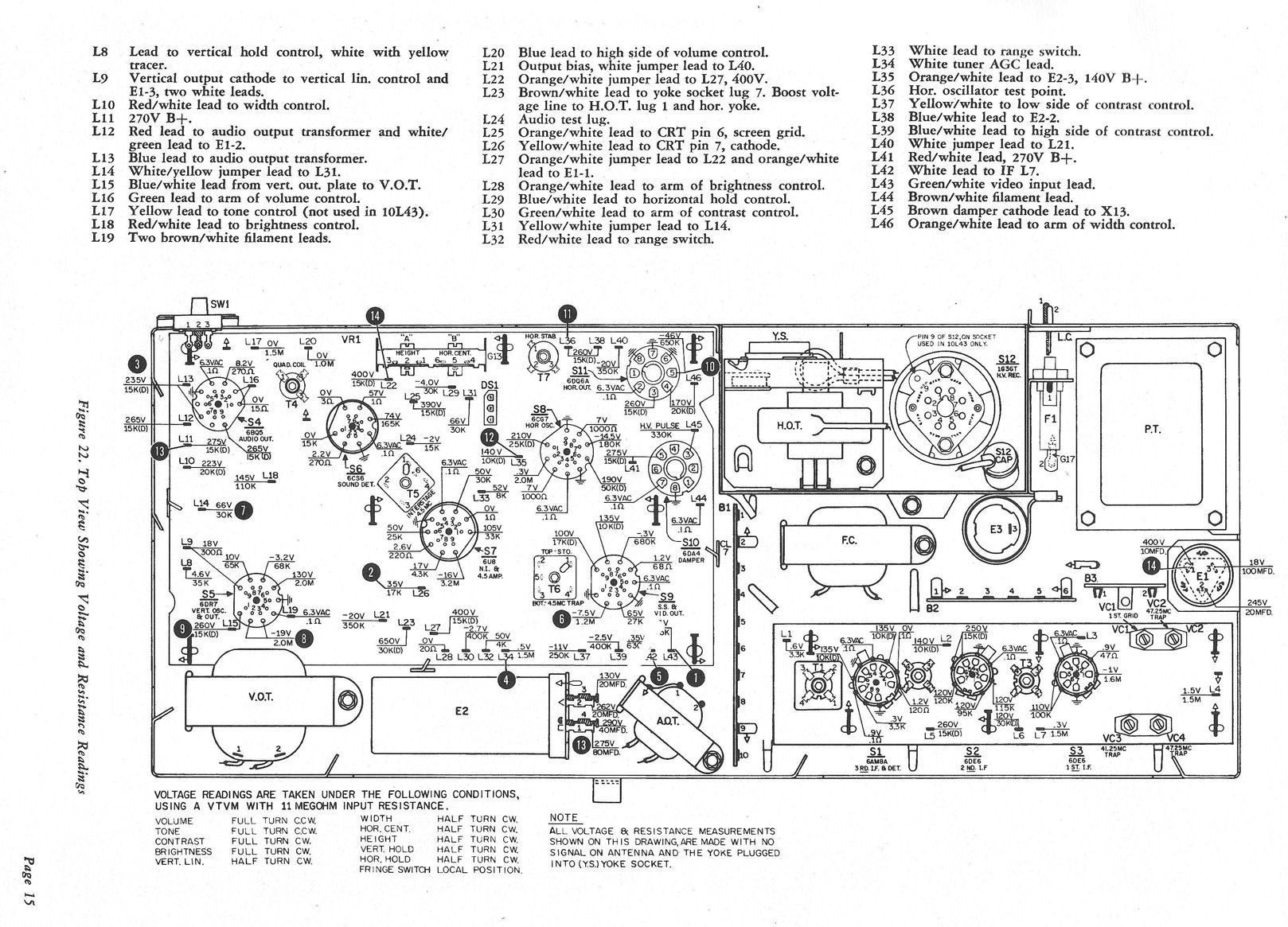
Later in the project, I bought an original Philco factory service manual, which
has two diagrams showing everything that I had drawn by hand, and more. The first
one identifies every component and lug on the board. The second page identifies every lead
and it also gives voltage and resistance values for tubes on the main chassis.


My Philco Miss America article illustrates
replacing capacitors
on printed circuit boards, which may be useful if you haven't serviced this type of board before.
Removing the board is tedious and it increases the risk of wiring errors
and damage to the leads or terminals, so I was determined to avoid pulling
it more than once. In addition to paper capacitors, I also replaced mica capacitors
in the horizontal and vertical sweep circuits.
I also tested all of the board's resistors and replaced any that measured more than 20% off the
specified value. In this I was informed by my earlier Predicta restoration, where I
had discovered some dodgy resistors after pulling the board a second time.
I debated whether to replace couplates on the board before reinstalling it. This
was a pure judgment call. On one hand, some of these multi-component packages are
known to be troublesome, and there's no practical way to test them other than by
substitution. On the other hand, the TV had produced a passable picture before
restoration, so for all I knew, the couplates might all be good.
I decided to leave the couplates alone for the time being.
Adding Quick Disconnects to the PC Board
While discussing this project in the
VideoKarma forum, someone
asked whether it would be useful to attach "quick disconnects" to
the board leads. In theory, this sounds great. Instead of laboriously unwrapping and
unsoldering three dozen leads, you could simply unplug them and pop the board out!
This idea had been raised before, but I couldn't recall anyone trying it,
so I thought it was worth investigating.
At a nearby surplus store, I found some Molex connectors
that looked usable. After I installed one, however, it seemed larger than I liked:

One connector doesn't take up so much space, but multiplying that
connector by three dozen might create a mess.
Next, I got a bunch of Anderson power pole connectors, thinking they might
fill the bill. But when I laid several of them near the
places where they'd connect, the sight was dismaying.


If each connector was wired with a short lead to its pin on the
board, you would end up with lots of leads and connectors above
the board. This could really interfere with everyday service.
With so much stuff in the way, it would be hard to see a tube, much less replace it. And
it would complicate diagnostics like snaking an instrument
probe or a lead in to a test point deep inside, to measure
something while the TV was turned on.
The best idea that came out of this discussion was to leave all of the board
pins bare and solder a female Molex .062 connector on the end of each lead, insulating
it with a bit of shrink tubing. Then you could plug each lead directly onto its pin,
just as the Siesta's video lead plugs onto a pin.
On reflection, I rejected that method, too. In my opinion, the advantage of being able
to quickly pull the board is outweighed by the risk of creating intermittent connections.
The Predicta board is prone to flaky connections under the best
circumstances. It seemed unwise to surround the board with three dozen connectors
that might be nudged loose by accident during routine service, and whose
contacts may become corroded or dirty over time.
The last thing I wanted was to make this finicky board even more finicky!
I abandoned the quick-disconnect scheme and proceeded to restore
my set the old fashioned way.
Loosening the Main Circuit Board
An alternative to adding quick disconnects is to free the main board from
its ground lugs and carefully push it away from the chassis, as far as the slack
in its connector leads will permit.
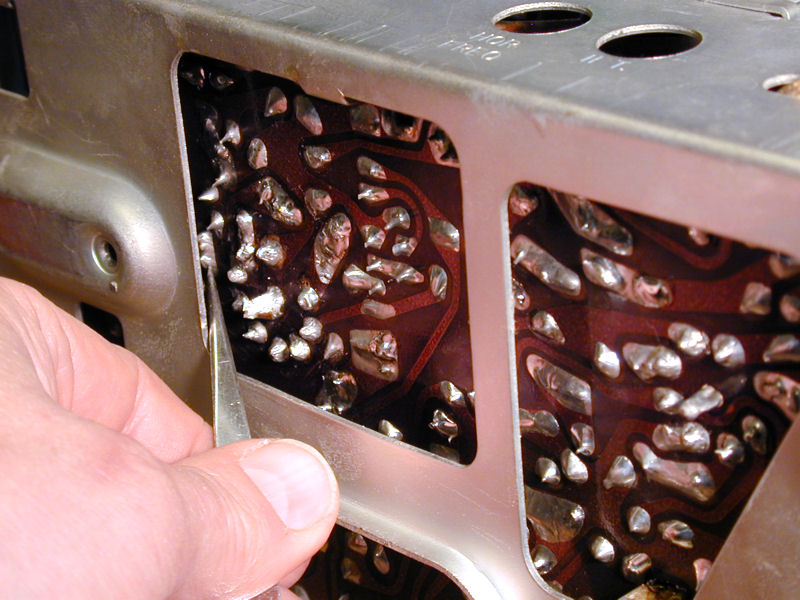
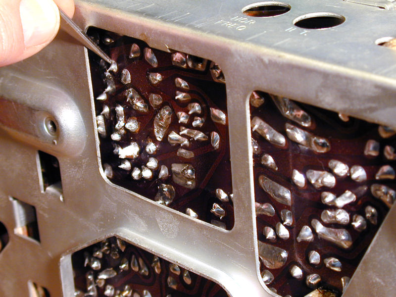
This view from below shows the board
loosened from the ground lugs and pushed away from the chassis:

This doesn't give access to the entire foil side of the board, but it provides
enough elbow room to reach many more components through the access holes. This
is how I replaced three of the Predicta's couplates, as explained below.
Unsoldering the ground lugs takes only a couple of minutes. A solder sucker will remove
excess solder, and then the lugs slide through their slots when you lift the board.
Servicing the High Voltage Section
After recapping the board, I removed the high voltage cage, cleaned everything with isopropyl alcohol, and inspected the
flyback transformer and the socket of the 1B3GT HV rectifier tube.
I also measured and recorded the resistance of the windings of the yoke and flyback
transformer, comparing them to the values given in the manuals. As an additional
check, I tested these components with my EICO 944 flyback/yoke tester. They
all passed with flying colors.
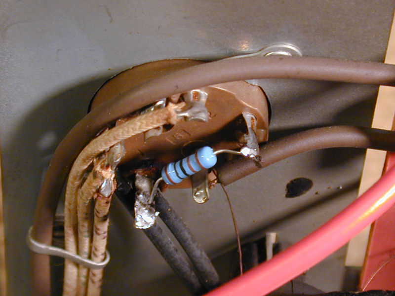
While in the neighborhood, I replaced a couple of resistors. Here's one (R71)
on the yoke socket, normally hidden inside the cage:

I also replaced R72 under the 1B3GT socket:

The black wax coating around the flyback transformer had a few surface
cracks but it looked better than many flybacks I have seen before. Resistance
checks of its windings gave no cause for alarm and the TV had produced
a nice, bright picture, so I left the flyback alone.
I replaced the rectifier socket and cage cover, reinstalled the main PC board,
and powered up the TV.
Loss of High Voltage
After I remounted the board, the TV's audio worked, but the high voltage supply
fizzled. The screen flickered to life for one or two minutes and then went dark.
I first checked a number of obvious things, substituting tubes, testing voltages in
the horizontal and high voltage circuits, and so on. The grid voltage on the
6DQ6 horizontal output tube was deficient—zero volts where you'd expect
-45 volts—and the waveform at the grid did not match the model
given in the service manual.
Since I had been methodical about replacing components and reinstalling the main
board, my first impulse was to suspect that the N7 couplate had failed.
A couplate is a 1950s-style integrated circuit
with a few capacitors and resistors in a flat envelope.
The N7 couplate processes the signal from the horizontal oscillator tube and
delivers it to the grid of the horizontal output tube.
Original factory couplates are no longer available, and I doubt you'd want
to use one anyway, since its old resistors and capacitors might
degrade with age, just like their larger 1950s counterparts. It's possible to build
a substitute, however, and I had done that when restoring my first Predicta.
Before going to that trouble, I called on the
VideoKarma forum, in case someone had a better idea.
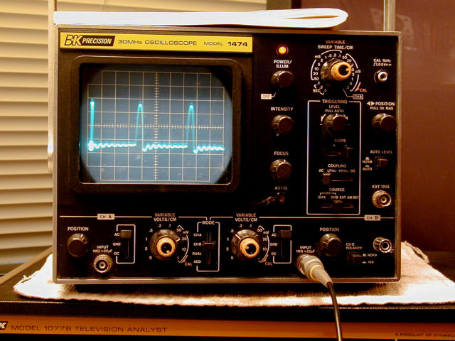
Testing by Horizontal Signal Substitution
That discussion produced several good suggestions, including using
my BK 1077B Television Analyst to substitute
a drive signal for the signal that should be sent to the grid of the
6DQ6 horizontal output tube via the N7 couplate.
The idea is to zero in on the trouble spot. If the high voltage
reappears, then I'll know that the problem had to be somewhere upstream
of the 6DQ6 grid. That upstream territory includes the N7 couplate.
On the other hand, if HV is still lacking after I provide a known-good
signal at the grid, that indicates a problem downstream, such as a bad
6DQ6 socket or bad flyback transformer.
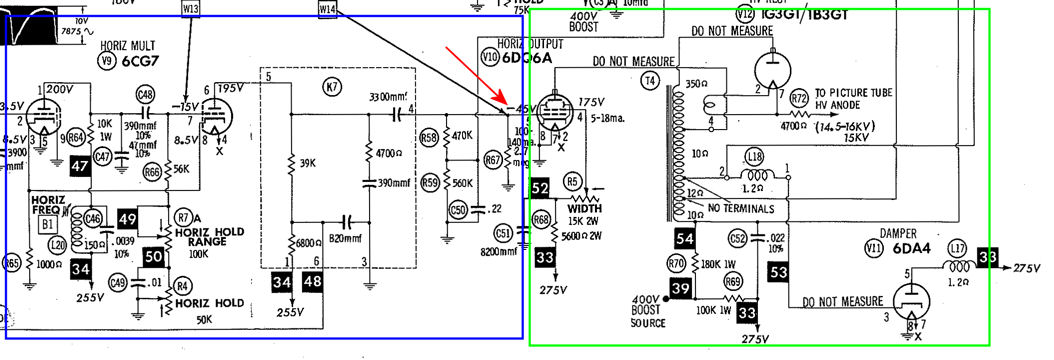
To illustrate, here's a portion of the Sams schematic, whose horizontal section
is a little easier to follow than the Philco version (the Sams part number for the
couplate is K7).
The red arrow shows where I'll inject the test signal. The blue rectangle
roughly outlines the upstream zone; if HV reappears, then we suspect a problem there.
The green rectangle includes downstream components; if HV doesn't come back, something
must be funky down that way.
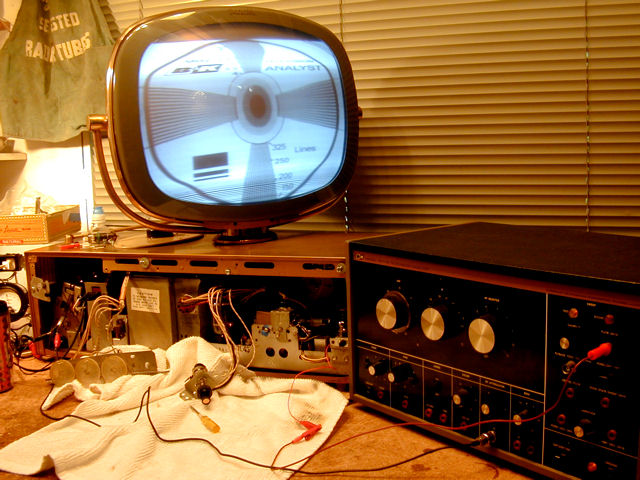
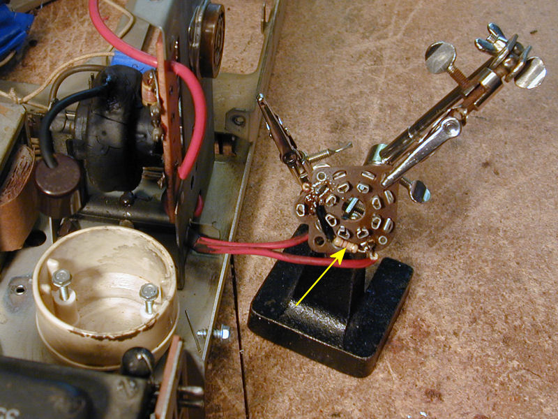
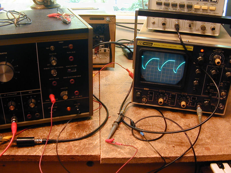
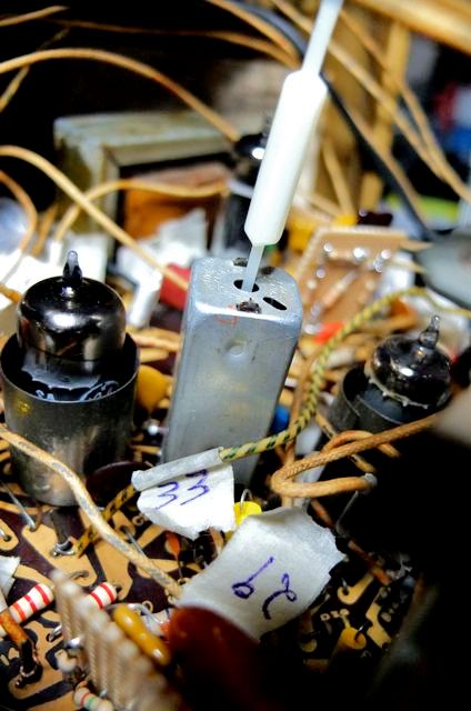
I first checked the test signal from the BK 1077B Analyst to make sure it
was operational and approximately the right shape. So far, so good:

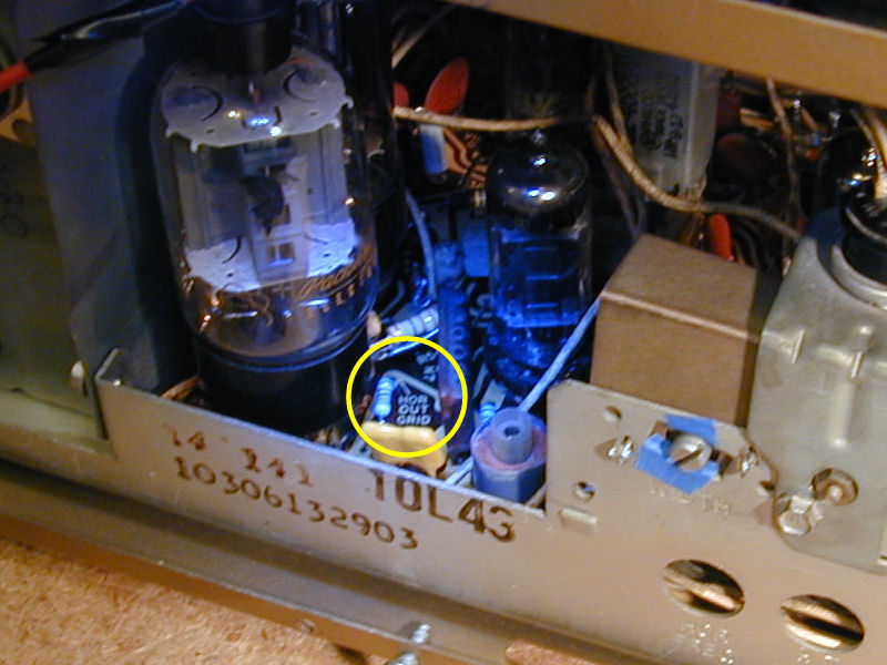
A label on the PC board showed where to connect the test signal to
the grid of the horizontal output tube (the blue in the photo
comes from my LED flashlight, not a strange condition in the TV):

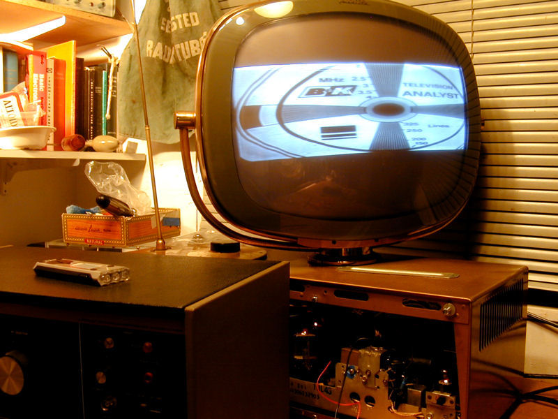
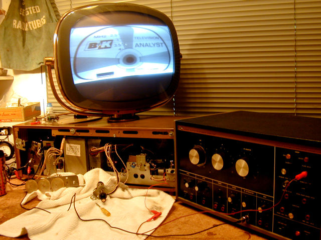
The substitute drive signal brought back the high voltage, and with it, the raster.
We have a picture again!

(In the previous photo, the image height is deficient.
That was also true when I tried the TV before starting restoration,
so I deferred the height issue for later consideration.)
In the course of servicing the main board, I had already replaced all of
the capacitors and resistors around the 6CG7 horizontal multivibrator
and 6DG6 output tubes. This substitution test convinced me that the N7 couplate was
at fault, so I proceeded to build a replacement.
Replacing the N7 Horizontal Couplate
Now, I faced a decision: whether to pull the main PC board a second
time or try to replace the N7 couplate from above. Turning the chassis over,
I could see that the foil-side connection points for the couplate would
be reachable if I unsoldered the board's ground lugs and pushed it out
as described earlier.


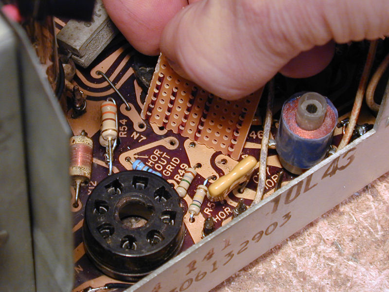
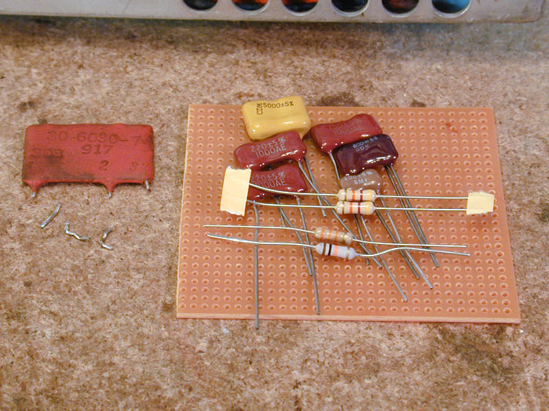
Removing the old couplate was a bit pesky.
Its four lugs fit very tightly into the holes in the board, and even after sucking away excess solder, it
was impossible to remove the couplate intact, so I cut it
into pieces above the board and then removed each lug separately. Here are
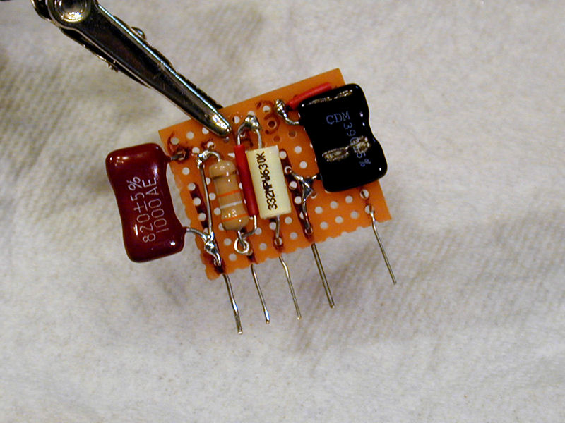
the remains of the couplate and the parts that will replace it:

The couplate has five terminals and it contains three
resistors and three capacitors. Below is its schematic from the Philco manual.
The components inside the couplate are bordered with a dashed rectangle.
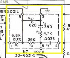
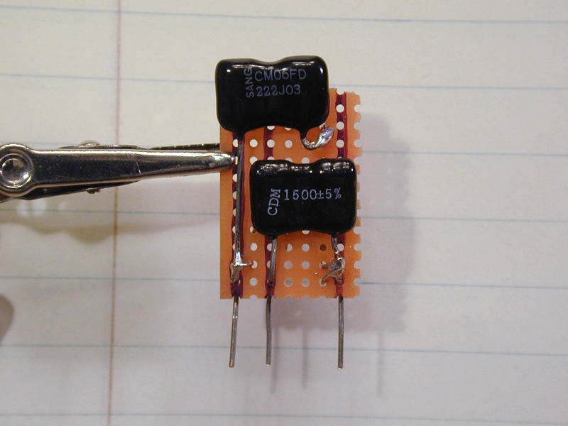
I cut a piece of perforated project board and marked where its five
terminals will be located. (Although the N7 terminals
are numbered 1-6, terminal 2 is not used.) Now, I'm trying the
new board for size before populating it:

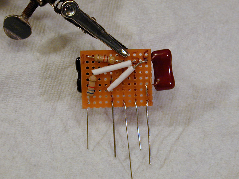
Here's the new N7 couplate under construction. To save space, I used both sides of
the perf board.

As often happens, the most convenient physical layout doesn't mirror the
logical diagram in the schematic, so a little mental effort is needed to
see how the components match the diagram.
After you build a couplate replacement, you could wrap some tape around it or
dip it in an insulating material, if you like. I left this one bare for the time being,
until I confirmed that it worked.
Installing the new couplate was easier than removing the old one and
it worked like a charm. The high voltage and picture returned and the horizontal
lock was stable:
That's one more problem solved, although the vertical problem persisted.
Deficient Height
When servicing the board, I had replaced all of the capacitors and resistors around
the 6DR7 vertical tube, so I assumed that those new components were good. Now, I made
voltage and resistance tests on all of that tube's pins and I checked the values of
the potentiometers for height and vertical linearity.
While the chassis is in the cabinet, you might think that much of it is inaccessible
for powered-up testing, but that's not entirely true. Yes, the underside of the circuit board
is out of reach, but in many places on top of the board, you can sneak in a
clip lead or probe for testing.
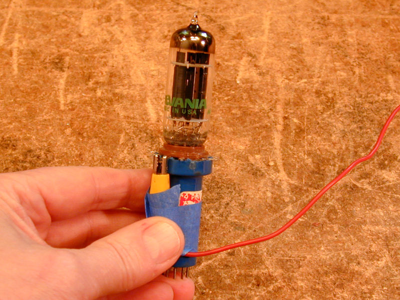
Extenders make it possible to reach a tube's pins
for diagnostics. In this photo, I have plugged the 6DR7 tube into the blue
extender and taped a clip lead to pin 3. This pin is normally inaccessible when
the tube is plugged in, far back in the interior, but now I can reinsert it in
the chassis and bring the lead out to my oscilloscope or multimeter.

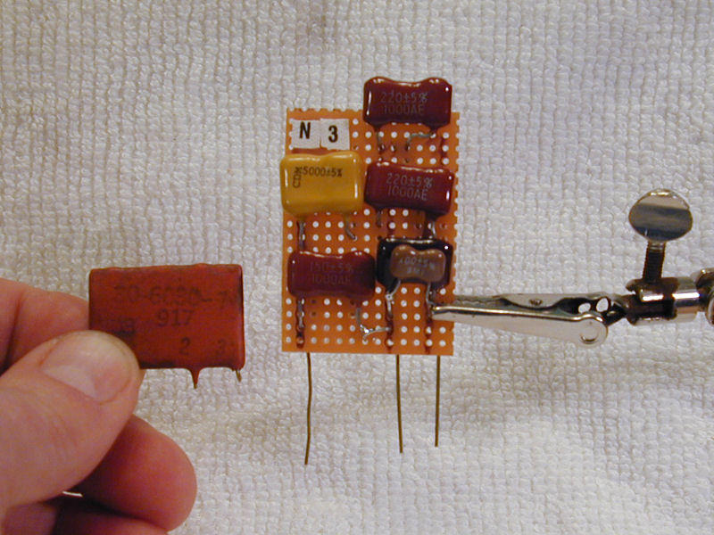
Resistance and voltage tests didn't turn up any smoking guns, so I decided to
replace the N2 and N3 couplates. These sometimes fail in Predictas, and the
only reasonable way to test them is by substitution. Even if replacement doesn't
fix the problem, it should help to isolate the cause by removing couplates
(with a total of 10 internal components) from the equation.
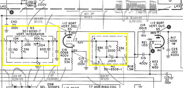
Replacing the Vertical Stage Couplates
Seen in the schematic, the N3 couplate is the vertical integrator,
which processes the signal from the sync separator tube and passes the resulting
waveform to the vertical oscillator. The N2 couplate returns feedback
from the 6DR7 pin 1 plate to its pin 7 grid.
When restoring my first Predicta, I had replaced its vertical feedback
couplate, so building N2 was familiar, although this one used
slightly different resistor values.

Again, I found it convenient to put capacitors on one side and resistors on the other.
The N3 couplate is more complex, with three capacitors, two resistors,
and a resistor-capacitor combination shown as a 90K resistor
(R3) with a .004-mfd capacitor (C2) distributed across its length.
Following advice from my earlier Predicta project, I replaced that
component with a 90K resistor (actually, two 47K resistors in series)
and two .002-mfd capacitors mounted on either side of it.
You can also build the R3 component with two 47K resistors in series
and three .001-mfd capacitors, one connected between the resistors and the
other two at their ends.
Here is N3 under construction:

Testing by Vertical Signal Substitution
With the new couplates in place, the vertical stability was great, but the
height was no better than before. Rats! Testing voltages and double-checking
my replacements didn't uncover any obvious cause for the problem.
I renewed the discussion on VideoKarma, wondering whether I should
suspect the vertical output transformer, since I had replaced just about
every other component involved with height.
As before, I got many useful suggestions, which you can read in the full
discussion
if you're curious.
Taking a cue from my earlier experience with the high voltage issue,
I remembered that my BK TV Analyst could also generate a vertical plate drive
signal. Perhaps substituting that signal would help isolate the problem.
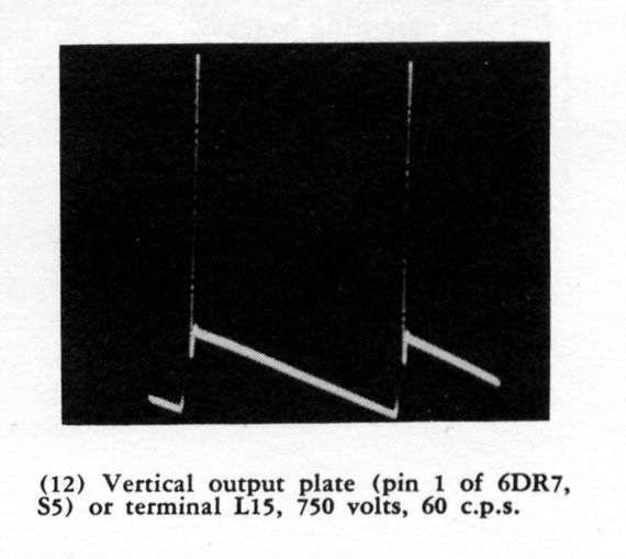
The Philco manual showed a model waveform for the signal at pin 1 of
the 6DR7 tube, and the signal produced by my TV Analyst looked similar:


I pulled out the 6DR7 vertical output tube, thus removing its signal from the circuit,
and then injected the vertical plate drive signal from the Analyst at the
pin 1 (plate) connection point. The results were ambiguous:

The first photo shows the screen image with the
1077B's Amplitude control set about midway. The height is still deficient.
The second shows the screen with the Amplitude control turned up all the way.
Although the second image filled the screen, the lower half of the screen
was distorted and the overall linearity was dreadful. As one forum member remarked,
perhaps the excessive amplitude merely masked a problem in the output
stage or elsewhere.
Since the 1077B also provides a vertical grid drive signal, I tried substituting
that signal (at C19). The results were no better than when injecting a plate drive signal.
In short, signal substitution for the vertical stage didn't reveal an obvious culprit,
as it had with the horizontal problem.
Testing and More Testing
I began another round of testing and substitution, in search of an answer.
In the next photo, I have disconnected the
vertical linearity potentiometer (VR2) and its bypass capacitor (E1-3)
and substituted a fixed resistor and a new 100-mfd cap:

Substituting fixed resistors of different values didn't improve
the height, either.
Again, no cure. But this substitution told me that the problem wasn't caused by a
defective linearity pot, and that the new electrolytic I had replaced earlier
wasn't defective or miswired.
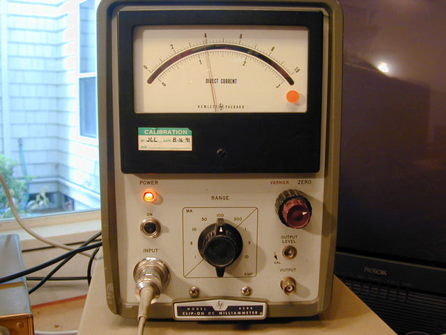
In addition to testing voltages and waveforms on the 6DR7 vertical tube,
I used my HP 428B milliammeter to
measure its pin 9 cathode current. Here, with the TV's Width control turned fully
clockwise, it measures around 38 or 39 milliamps:

I double-checked that reading with an analog multimeter and got the same results.
The cathode current was basically OK, approximately 30 milliamps as given in the
Sams manual if I dialed the Width control down to an average setting.
Another forum member suggested temporarily shorting out the thermistor (R64) which is connected
between the two windings of the vertical yoke.
In previous measurements from the yoke plug, I had determined that the winding resistances
looked OK, with the thermistor contributing about 7 ohms of resistance. That
was slightly higher than the specified value of 4 ohms (when cold), but
it showed that the thermistor was not open or shorted.
Strange things sometimes happen when a component heats up, however. To
eliminate the thermistor as a trouble source, I slid the yoke off the picture tube neck,
shorted the thermistor with a clip lead to remove it from the circuit, and reinstalled the yoke.


Eliminating the thermistor didn't improve the height, either, so I removed
the clip lead and kept plugging away.
Height Problem Solved
While discussing the couplates I had replaced, one forum member asked about
capacitor C16, which is attached to pin 3 of the N3 vertical integrator.
That capacitor had been replaced when I recapped the main circuit board.
Double-checking it now, I saw that I had used the wrong value, installing a cap labeled
683 (.068 mfd) rather than 682 (.0068). A rookie mistake—Arrgggh!
Installing the correct value brought the screen back to full height.

This illustrates the risk of replacing many parts at once. When restoring a more traditional
TV, you can usually power up the set for a quick test after replacing every few
parts, so a flub like this is quickly caught and corrected.
That's how I normally work, but you can't restore a Predicta that way, unless you
want to uninstall and reinstall the main board a dozen times or more.
VideoKarma member DaveVM recommended a tactic to help
avoid such errors: before installing a new cap, check its value on a capacitor tester.
This ensures that the new part isn't defective, and more importantly,
it's a final safeguard against inadvertently installing the wrong part.
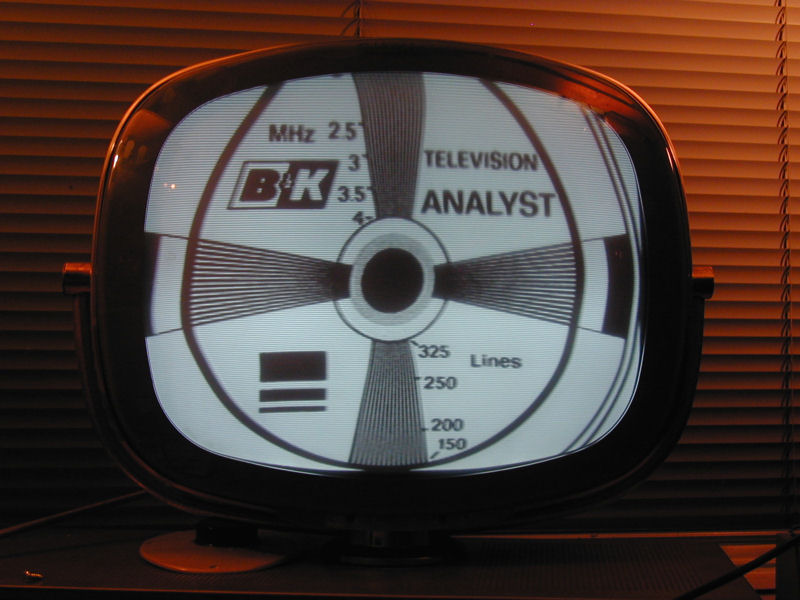
Vertical Linearity and Stability
The previous screen shot looked promising, but a test pattern showed that the
vertical linearity was less than ideal.

The upper half of the screen is stretched vertically, making the
circle somewhat pear shaped. This is the best I could get when adjusting
both the height and linearity controls for the best compromise (they
are interactive).
Many old TVs have slight defects in screen geometry, which don't matter
a lot in everyday viewing, but it was harder to overlook the lack of vertical
stability. Vertical lock was hard to obtain, and when the vertical
sync was far off, it blinked to a bright horizontal line (momentary
loss of all vertical deflection) every now and then.
After replacing C16, the height was actually a little excessive. I
substituted slightly higher values (reducing the height) until I was able
to fit the entire image on the screen, with only slight underscan as
needed to obtain better linearity.
I also adjusted the value of two other components, particularly
R14, which, I had earlier been advised, affects the vertical
hold range. These changes improved the stability as well as linearity.
Here's a test pattern at this stage:

When working on linearity, don't forget about the centering adjusters,
located on the yoke. I found that the vertical centering control had been
adjusted way off, perhaps to compensate for some aging component. After
I centered that, it was much easier to make the picture right using
the height and linearity adjusters.
Horizontal and Audio Alignment
At last, the picture looked satisfactory, so I finished by working through the
horizontal and audio alignment procedures, and then played a couple of movies to make sure
the television was stable.
This Predicta's audio is surprisingly good. Perhaps the new speaker is better quality
than Philco's original issue. This set lacks a tone control, but you can adjust the
tone by changing the value of C17, the tone compensating capacitor. Increasing
the capacitance cuts the treble, this improving the bass response. You don't want
to increase it too much, of course, or the tone becomes muddy.
Speaking of audio alignment, fellow collector Russ Barnett shared some advice about
the correct tools and procedure. Transformers T5 and T6 both have concentric cores of different sizes.
In some transformers, you would adjust one core from the top and the other from the bottom.
With this type, you adjust both cores from the top using different size tools, shown here:

On top is a 3/32" (.09375") Delrin plastic hex tool used for the top cores.
The tool on the bottom is also 3/32" on the tip but it then tapers down to about .07".
This is used on the bottom cores.
You can get such tools from Antique Electronic Supply.
These photos show the approximate location of the bottom core in the transformer can:

Russ notes that the hex cores may not be lined up perfectly with each other, so extracting
the tool after tweaking the bottom core is a delicate little dance. First you pull up
until you feel the tip disengage from the bottom core (about 1/4" to 1/2").
Then you pull up gently until you feel the the tip touch the underside of the upper
core. Rotate the tool until the hex tip lines up with the upper core.
Then you can pull the tool straight up and out
Thanks to Russ for providing this alignment information.
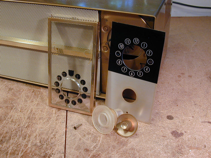
After adjusting the tone to my taste, I declared the electronics done. I gave the dial
parts and knobs a cleaning and polish before putting it all back together.

Final Thoughts
I'd say this Predicta works at least as well as my first one.
On the whole, this was a pretty straightforward project, not counting the
detour caused by installing one part with the wrong value. I got a kick out of
making this Predicta operational, after seeing it
in a memorable collection years earlier. Perhaps the previous owner
would appreciate the effort spent in making it work again.
|