RCA CTC-7 Color Television (1958)


This RCA CTC-7 color television makes a fine companion to my other two
"roundies," the
1954 CT-100 and a
1962 CTC-11. It was built in 1958, four years
after the path breaking CT-100 and four years before the CTC-11.
Meet the RCA CTC-7
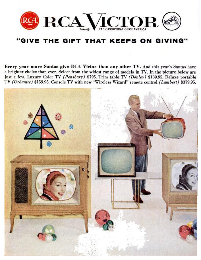
RCA offered its CTC-7 color TVs with many cabinet styles, colors, and
options. My set has a mahogany Pensbury cabinet. This 1958 ad shows a Pensbury with
a blonde finish.
The ten (!) other cabinet styles were named Abington, Anderson, Brandywine, Grenoble,
Meredith, Sanford, Southbridge, Townsend, Whitmore, and Worthington. Remote
control and UHF tuning were extra-cost options.
Color TVs were very expensive in 1958. My CTC-7 in a Pensbury cabinet, with manual VHF tuner,
sold for $795. By comparison, $2300 would buy you a new 1958 Chevrolet Biscayne auto.
As with cars, financing plans were offered to let you pay for your
new color TV over a period of years.
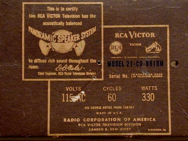
The model number of my CTC-7 is 21-CD-8910M, seen on the back cover:

RCA sold the CTC-7 under 46 different model numbers. All of them start with
21-C, which means 21-inch color television. The 8910 identifies my cabinet and M
means manual tuning. Optional UHF tuners and remote controls were denoted by
U and R in model numbers.
Scoring a Seven
Finding this desirable early color set was a stroke of luck. I happened to notice the seller's
ad in the local craigslist only minutes after it was
posted. The asking price was $55, quite a bargain.
A quick phone call confirmed that it was a model CTC-7 and
soon I was speeding down the freeway with cash in my jeans.
The seller met me in front of a big old apartment building. As we walked to the door, I looked
up and joked, "I hope you're not gonna tell me it's located on the top floor." Just my
luck—it was! However, the building had an elevator and the seller had a sturdy,
padded moving dolly, so getting it down to street level was no problem.
Muscling this heavy console into the back of my little SUV was trickier. The top
of the TV only cleared the truck's ceiling by about half an inch. When I
got home, all of my helpers were AWOL, so I had to leave it in the truck overnight.

First Look
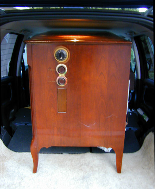
By the next morning, the CTC-7 was safely stowed in the garage and I could get a better
look at my new find. The cabinet was in excellent shape. I hauled out my trusty
panther lamp to take an "as found" photo.
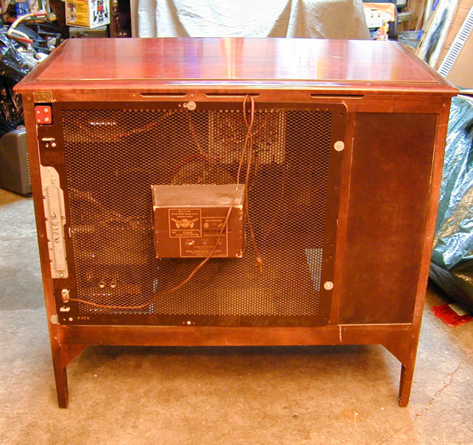
The Pensbury cabinet is a quality piece of work. The
lacquer finish is deep and lustrous and much of the cabinet is solid wood
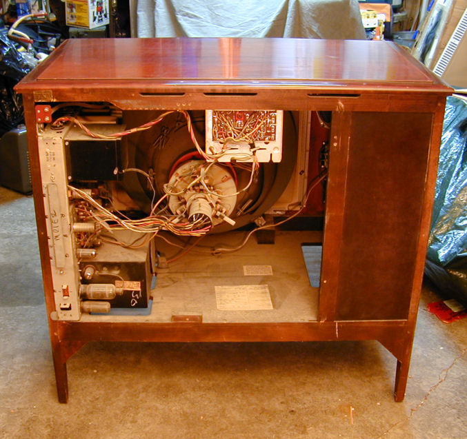
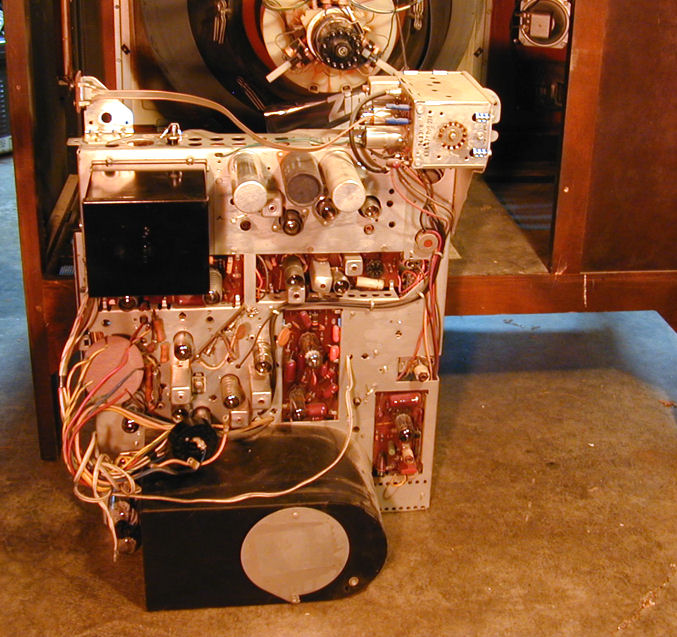
rather than veneer. Here are two rear views:

The interior was dusty but not caked with layers of old cooking grease
and tobacco tar, as many old TVs are. Cleanup will be easy.
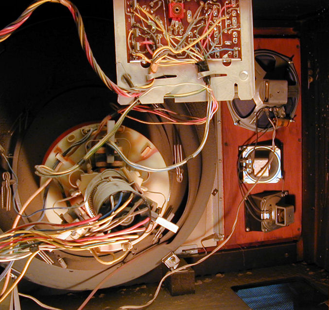
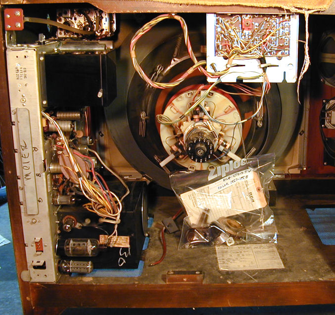
Like my CTC-11, the chassis
stands vertically along one side with a small convergence board on the top
rear edge.
In this photo you'll see a welcome feature: triple speakers,
with a big woofer and two angle-mounted tweeters. This deluxe
CTC-7 has high-fidelity audio!

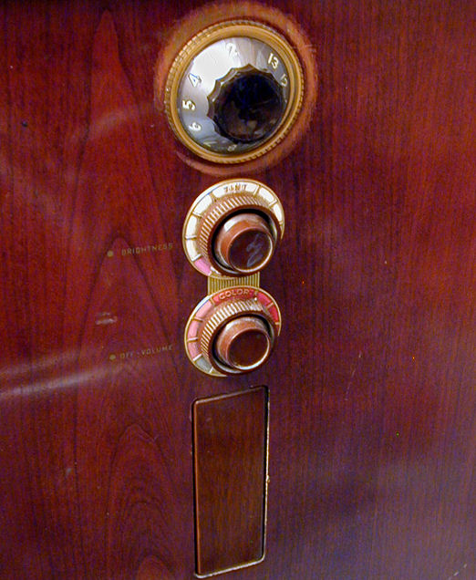
Next is a view of the knobs and control cover on the side of the cabinet.
Notice the wear circle around the fine tuner. Early color TVs demanded
careful fine tuning and this set was no exception. It
won't be difficult to touch up this area.
Behind a small tilt panel are the less often used controls: Tone, Contrast, Vertical, and
Horizontal.

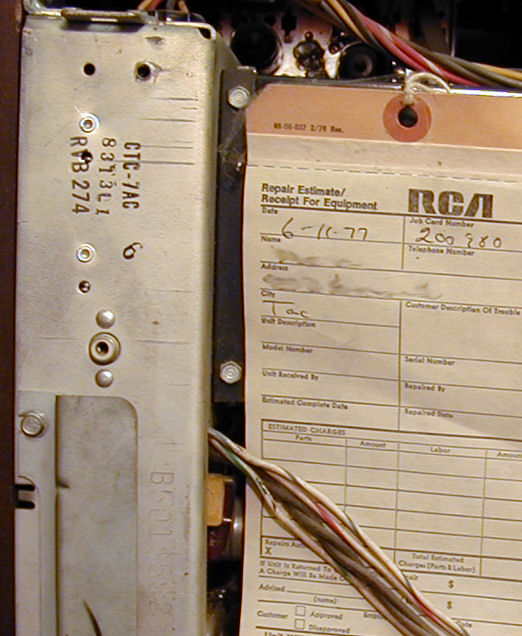
A rubber stamp identifies this as a CTC-7AC. Stamped into the
chassis metal is serial number B5018582. The same number appears on a tag
on the picture tube shield.

While cleaning up, I found a repair tag dated 1977
(I blurred out the owner's name and address to protect her privacy).
No work is listed, so perhaps the serviceman lost this tag and filled
out another one, or possibly the owners decided not to repair the
set after they got a price estimate.
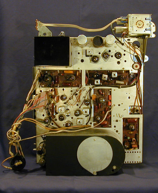
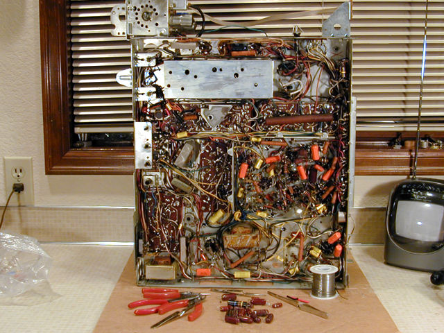
Electronic Design
The CTC-7 design clearly evolved from the seminal CT-100,
yet it shares many features with later color sets like my
CTC-11. Here is the unrestored chassis:
The overall CTC-7 chassis layout is very similar to the CT-100. Major components
such as the tuner and power supplies are in the same places, although some sections
have migrated onto printed circuit boards.
The chassis is mounted sideways rather than flat in the cabinet. This simple change from the CT-100
cost little to implement and it gave the customer an obvious ergonomic benefit. Flipping the
chassis on its side moved the tuner and other user controls near the top of the cabinet
rather than under the screen. The same configuration was carried forward in my CTC-11
and many other televisions.
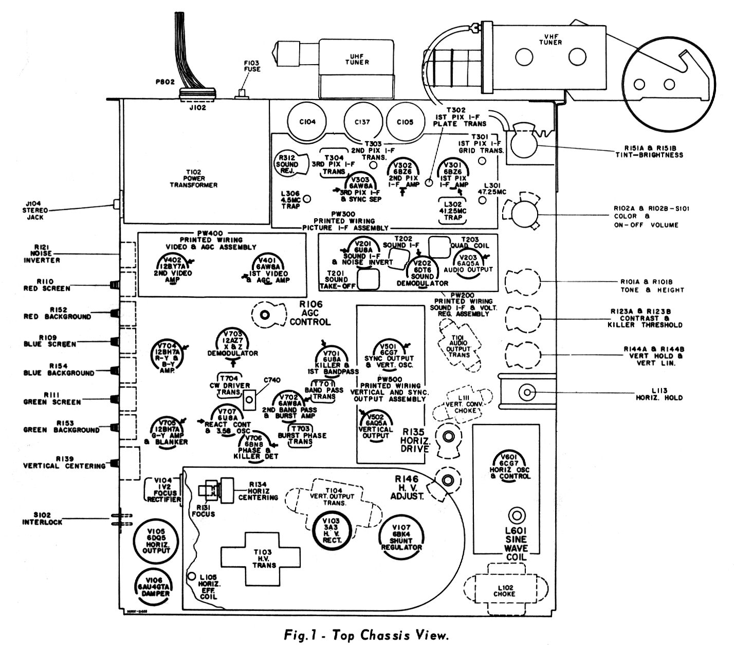
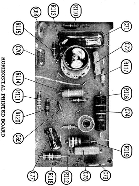
This diagram shows the chassis layout in detail (click for an expanded view):

Here is a list of the CTC-7's 24 tubes:
| Tube |
Type |
Function |
| V1 |
6BZ6 |
1st Video IF Amplifier |
| V2 |
6BZ6 |
2nd Video IF Amplifier |
| V3 |
6AW8A |
3rd Video IF / Sync. Sep. |
| V4 |
6AW8A |
Video Amp. / AGC Keying |
| V5 |
12BY7A |
Video Output |
| V6 |
6U8A |
Audio IF Amp. / Noise Inverter |
| V7 |
6DT6 |
Audio Detector |
| V8 |
6AQ5A |
Audio Output |
| V9 |
6CG7 |
Sync. Amp. / Vert. Mult. |
| V10 |
6AQ5A |
Vert. Mult. / Vert. Output |
| V11 |
6CG7 |
Horizontal AFC / Horiz. Osc. |
| V12 |
6DQ5 |
Horizontal Output |
| V13 |
6AU4GTA |
Damper |
| V14 |
3A3 |
High Voltage Rectifier |
| V15 |
1V2 |
Focus Rectifier |
| V16 |
6BK4 |
High Voltage Regulator |
| V17 |
6U8A |
1st Chroma Band. / Color Killer |
| V18 |
6AW8A |
2nd Chroma Band. / Burst Amp. |
| V19 |
6BN8 |
Chroma Sync. Phase Detector |
| V20 |
6U8A |
Chroma Ref. Osc. & Control |
| V21 |
12AZ7 |
X Demodulator / Z Demod. |
| V22 |
12BH7A |
R-Y Amplifier / B-Y Amplifier |
| V23 |
6CG7 |
G-Y Amp. / Horiz. Blank. Amp. |
| V24 |
21CYP22 |
Picture Tube |
| V201 |
6BC8 |
RF Amplifier |
| V202 |
6CQ8 |
Mixer / Oscillator |
The CTC-7 uses solid state audio and video detectors as well as
rectifiers. My set has the VHF tuner with two tubes. The optional
UHF/VHF tuner had three tubes and a crystal mixer. Two versions of remote control
were offered, using either eight or nine tubes on a separate chassis. Transistors
were employed in the wireless remote transmitters.
My TV is a CTC-7AC. The "original recipe" CTC-7 (no AC) had some significant
differences, including two rectifier tubes.
In my article on CT-100 Electronic
Design, I described the so-called I-Q method of color demodulation and noted
that some later receivers used a simpler scheme known as Z-X. The CTC-7
uses Z-X demodulation, as does my newer CTC-11.
The Sams service manual for this TV
is Set 433, Folder 2.
This article refers to components by their Sams part numbers.
Another essential reference for CTC-7 owners is the RCA Television Service Clinic manual.
It's fifty pages long and written for engineers and servicemen who attended
RCA technical lectures. In addition to the usual service information, it discusses
the theory of operation for every major circuit.
Here is the complete RCA factory service manual (a 21-megabyte PDF file). To download
it, right-click the icon and choose Save Target As:
The RCA manual depicts the original CTC-7 design with dual rectifier tubes and
other differences from later versions. For version-specific
information, use the Sams manual.
Electronic Restoration
Only days after finding this TV, I got my wife a
Philco Miss America console
as a Valentine's present. I spent two weeks restoring that TV and writing an
article about it. Finally, I was able to turn my attention to the
CTC-7.
Checking and Cleaning Tubes
A critical question for every early color TV is the condition of its picture tube. If this
CRT is a dud, I could spend much more than $55 finding a good one to replace it!
My Sencore CR70 showed that this tube has strong emission. This photo shows
the test result for the Red gun; the Blue and Green guns also passed with flying colors.
A tedious but important initial chore is to test all 23 of the small tubes and
clean their pins. As frequently happens, almost all of them were good. Only
the 6DT6 audio demodulator looked too weak to work properly.
A side benefit of methodical tube testing is that you can clean the chassis
as you go and inspect each area for obvious trouble signs. Everything looked
nice, even the precious flyback transformer, which showed no dripping wax
or evidence of overheating.
Removing the Chassis
Removing the chassis is straightforward, following the directions in the
Sams manual. The knobs on my CTC-7 were stuck on very tightly. At
first, I was unable to pull any of them off. Rather
than break them or gouge the cabinet by trying to pry them off, I heated
each one gently with a heat gun. This expanded the plastic enough to let
me slowly ease it off.
On many TVs, the high-voltage anode lead is detachable at the picture tube
bell. On this set, you detach the other end of the lead from a tube socket inside the
high-voltage cage. After swiveling the round cage cover open, you pull the lead straight out.
In this photo, I have removed the knobs and chassis mounting bolts
and disconnected all of the necessary cables and leads from the
chassis. The little parts are bagged for safekeeping and all wires
are safely stowed.

Notice the red anode lead lying next to the high-voltage cage. Its other
end remains attached to the picture tube.
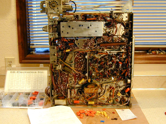
Kneeling behind the cabinet, I slid out the heavy chassis. Here is my
first close look at this set, which I'll come to know well in the
upcoming project.

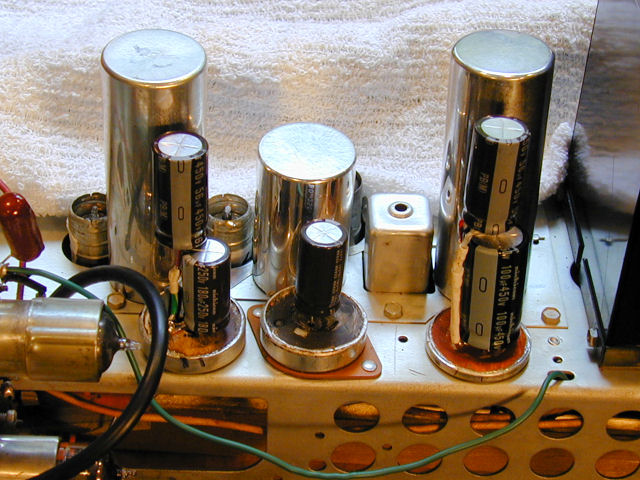
Let's note some major landmarks. In a black enameled box at upper left
is the massive power transformer. Three big cans immediately to its right
contain the electrolytic capacitors for the power supply. At
upper right is the shielded tuner.
At the bottom is the big, black high-voltage compartment. In the center
of the chassis we see
four of the CTC-7's six printed circuit boards: Horizontal, Vertical/Sync,
Audio/Noise inverter, Video/AGC. The convergence board is still
mounted on the cabinet above the neck of the picture tube and the
video IF board is concealed in a shield on the opposite side of
the chassis.
Restuffing Electrolytic Capacitor Cans on Undisturbed Bases
The CTC-7's primary electrolytic capacitors are contained in three cans,
like my CTC-11. I'll "restuff" them by putting new caps in the
original cans. It's possible to put the new electrolytics in the narrow
channel under the cans, as I did with my CTC-11, but that's a very tight fit.
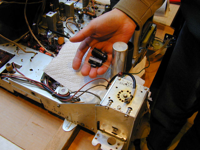
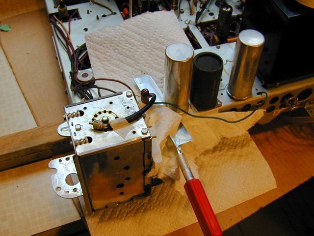
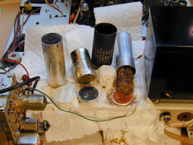
The first photo shows three new electrolytics that will go in the big aluminum can.
Notice the narrow board placed under the chassis. When you lay a CTC-7
chassis flat, provide a support to keep its weight off the control shafts.

I masked the chassis to keep dirt out. Sawing the can takes only a few minutes.


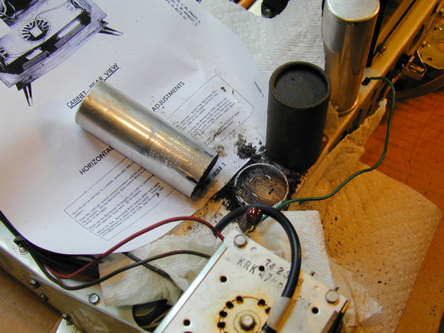
The second can has a cardboard cover. I was able to pull it off after softening the
tarry adhesive with a heat gun. The adhesive will clean up easily with mineral spirits.
If you're in a hurry, you could leave the cover in place and saw through it, but this
way the restuffed can will look completely original.

A cardboard cover is used to insulate a can whose exterior has a negative potential
that is "floating," meaning that it is not connected to the chassis and
thus presents a shock hazard. As
seen in the photo, this can is mounted on a nonconductive base to isolate it from
the chassis. My replacement capacitor will have no electrical connection to the can,
but I'll put the cardboard cover back on to preserve its original appearance.
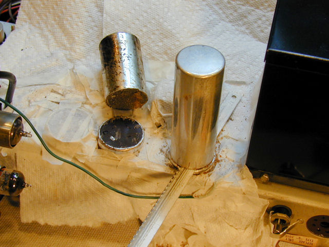
Let's proceed to the third can. For this one, I'll use a hacksaw blade because the hobby knife is too
wide to fit the narrow space. Notice how I have drawn little temporary registration
marks across the place where I'm making the cut. These will allow me to glue the can back exactly as before.
It's hard to make an absolutely symmetrical cut. If I match up the marks, any wobbly
edges will match up, too, and make a neat joint.

It's not always practical to saw a can. If it's mounted in the middle of a
chassis and surrounded by other components, there may be no room to
fit a saw blade or Dremel tool. In that case, you can either detach the
can from underneath and restuff it, or leave the can in place (disconnected, of
course) and install the new caps under the chassis. Those other methods are described
in my capacitor replacement article.
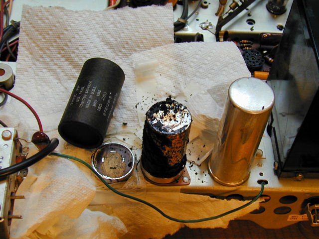
The next photo shows why "re-forming" old electrolytics is often
a losing game. The innards of the first two cans are not terribly dried out, but
the third one is a complete fossil. The paste electrolyte dried and shrank long
ago. In this condition, the capacitor may even have shorted and overheated,
very dangerous for a power transformer.

Removing the cans' old contents is also done with a heat gun. Drive a big wood
screw into the innards, get the can good and hot (wear gloves!) and then pull
everything out with a pliers. You can use mineral spirits to clean residue
inside the empty cans, if you like, but I don't get too obsessive about that.
Nobody will ever look inside them again!
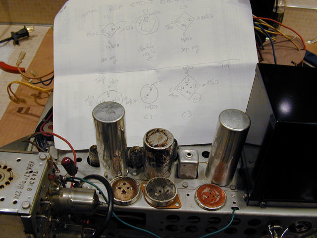
Next, I have drilled tiny holes in each base for the new capacitor leads, one hole
for each positive lead and an extra for the shared negative lead. The holes are
located inside the terminals (nearer the can center) rather than outside. This
avoids running into outward-radiating leads under the chassis.

Behind the empty cans you can see my hand-drawn cheat sheet. It shows the can bases
from above and below, indicating the location of every lead and the value (and Sams
part number) of each capacitor. This took a few extra minutes, but it let me
do the final hookup quickly, without a lot of head scratching and flipping
back and forth between my work and the schematic.
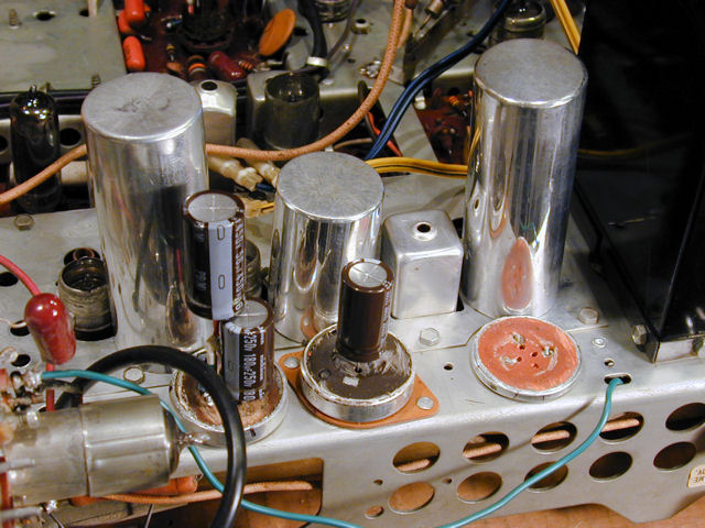
In the following photo, I'm two-thirds finished. The middle can needs only one
capacitor. In the first can, I have installed three, but the little low-voltage
cap is obscured behind the black tuner lead.

The third can is too small to contain all three capacitors, so this
assembly has only two caps. Insulate the hot leads carefully to avoid
any chance of short circuits. Your assemblies don't have to look beautiful
as long as they're safe and functional.

Finally, here's the orphan electrolytic that wouldn't fit in the third can, installed in
the cramped space under the chassis. If you look closely, you can see some of the
new cap leads snaking down through holes to be soldered to the old terminals.

A great advantage of this method is that it doesn't disturb the original
electrolytic wiring. Look at all of the wires in the previous photo. When I restored my CTC-11s,
all of the new electrolytics had to go into that narrow channel. It was hard to
fit everything in and avoid mangling the old leads.
We're done! The new electrolytics are installed and the cans are polished
and ready to put back on.

The new electrolytics are operational and I can proceed with restoring the
electronics. When I get around to cosmetics, I'll glue the cans
back on using JB Weld. The grey epoxy is a good color match for the
aluminum and after I clean the finished joint, it will be almost invisible.
First Power-Up and Raster
With new filters in the power supply, it's safe to power up the television under
controlled conditions. I'll keep a close eye on its power consumption with a wattmeter
and use a variac to gradually increase the supply voltage.
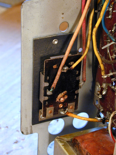
When you switch on a CTC-7, you'll notice a delay before any sound or video is
produced. The TV has a thermal switch, shown below. The switch lies between
the power source and the B+ circuits. When you turn on the TV, power is supplied
immediately to the filament circuits, allowing the tubes to warm up. Then the thermal
switch kicks in and you have audio and video. The "soft start" is
provided to prolong the life of tubes and other components, similar to the delay
circuit in my DuMont RA-103.
I haven't taken the switch apart, but I suspect it's similar to a
toaster switch with a bi-metallic strip, a much simpler alternative
to DuMont's over-engineered delay circuit.
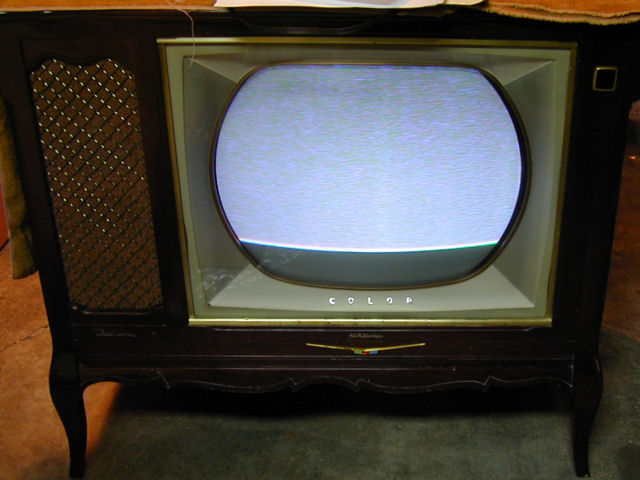
The first power-up was encouraging. As the next photo shows, the TV is
producing a raster (screen illumination) with full horizontal deflection, although
vertical deflection is insufficient. Sound from the speakers indicates life in
the audio section and colored snow on the screen suggests that the
color sections work. There is no hint of an image and
the speakers produce only static, so clearly the signal is not
getting through.
In the Good News department, a stable raster indicates health in the picture tube and flyback transformer.
Either of those components would expensive to replace, if you could find one at all.
Curing the No-Signal Condition
Let's begin with something easy. Faced with a no-signal condition, you
could try various strategies. One would be to connect a test signal
at the antenna terminals and then walk forward along the
signal path, tracing key points with an oscilloscope until the signal disappears.
You could also start at the other end, injecting a signal at a forward point such as the
video output tube; if a good image appeared there, you could walk backward along
the path until, again, you found a stage that wouldn't pass a signal.
Before getting fancy, however, let's check the obvious. Although I had previously
tested all of the small tubes, that's no guarantee that one of them hadn't just croaked
after its first exposure to working voltage in decades.
Sure enough, tube V201, the 6BC8 RF amplifier, had failed. I substituted an
equivalent 6BZ7 from my tube stash and powered up again.
Big improvement!
The audio was excellent and I got a coherent (well, semi-coherent) image for
the first time.
Vertical deflection is still lacking, but we already knew that. In addition, I can
now see that the horizontal frequency is wrong. The image is repeated horizontally
and overlapped. I was unable to correct this merely by turning
the horizontal hold control, although I could make it stabilize, mostly.
The horizontal oscillator is running near a multiple or fraction of the correct
frequency (15734.264 Hz). The hold circuit tries to lock onto that, keeping things
somewhat stable, but the image is incorrect.
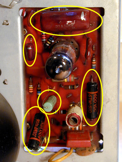
Recapping the Horizontal Deflection Board
Of all circuits in a television, the sweep circuits, and particularly the
horizontal, are the most failure-prone. They require precise timing, so
the mere aging of components, especially capacitors, can make problems.
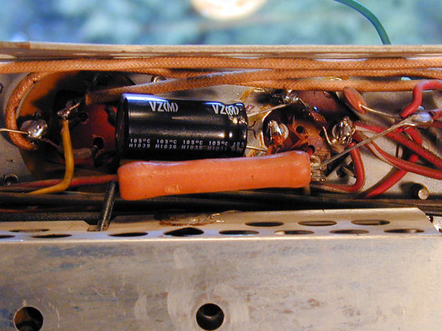
We can see at a glance that the horizontal section had issues in the past.
I have circled in yellow the capacitors most likely to fail. Only
two of them are original. The other three (one aqua and two black with orange markings)
are replacements.
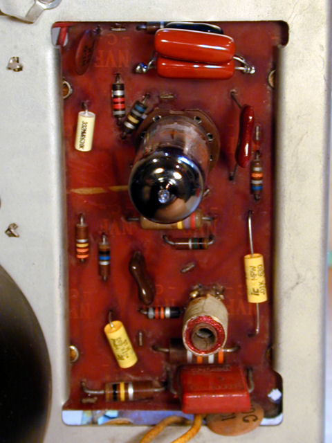
Even though the replacements are somewhat newer, they are still the old, unreliable
plastic-coated paper type, so I replaced all five caps, as seen in the third photo.
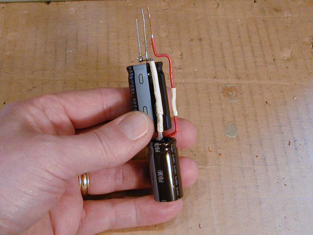
The big uppermost cap had an unusual value (.0027 mfd/1 KV), so I piggybacked
caps to make one that will work.
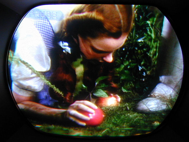
Yes, Dorothy, that's a color TV, all right!
I see real color for the first time and the horizontal problem is
cured. The picture is rock solid and I can't make it go
out of sync, even by turning the horizontal hold all the way in either direction.
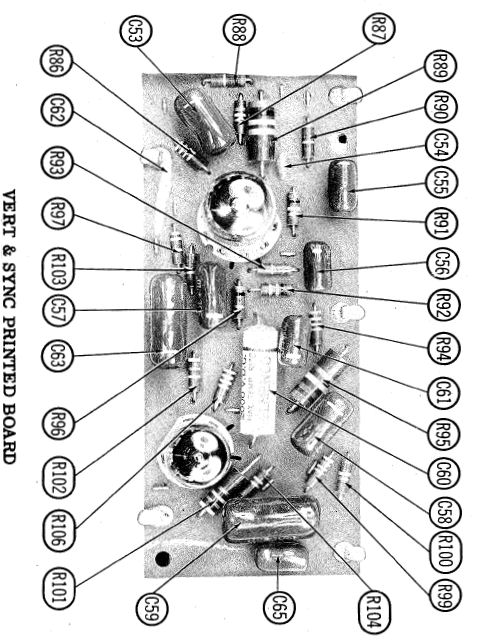
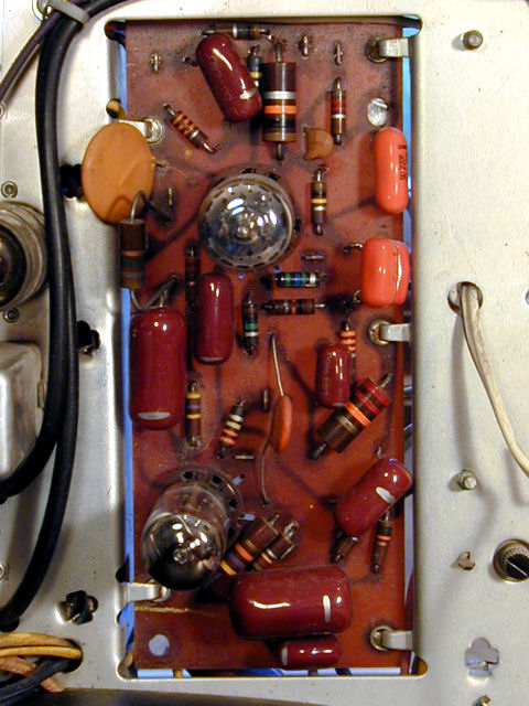
Recapping the Vertical Deflection Board
It doesn't take a Wizard to tell me where to go next. The vertical/sync board
has more caps than the horizontal board, but the result of replacing them is no less satisfying.

We have full deflection and the vertical hold is stable.
This project has gone smoothly so far, but we're still a long way from Kansas.
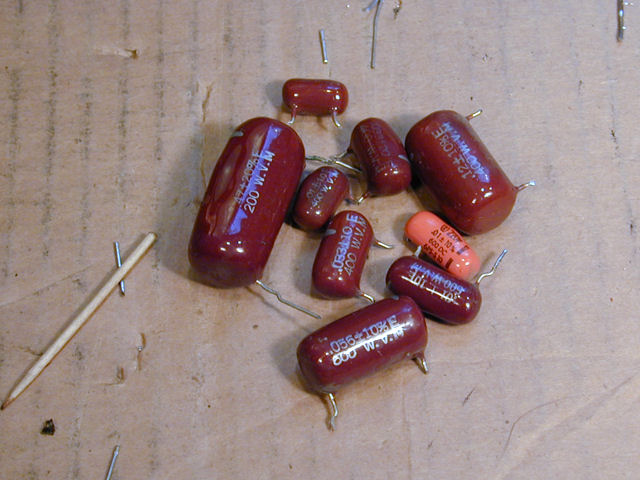
Recapping the Main Chassis
Although a number of the original "maroon drop" capacitors seem to be holding
up, I decided to replace the rest of them. Those on the sweep boards had suffered
a non-trivial failure rate, and there's nothing I hate more than "fixing"
a TV, only to haul it back into the shop a week or two later because some marginal
component finally gave out.
The remaining small capacitors were scattered around the chassis,
including a couple of boards that I hadn't visited, but the
majority were concentrated in the color sections. Here are before and
after photos:


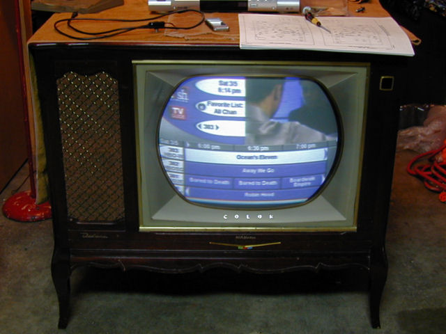
Mid-Course Status Check
My CTC-7 is shaping up! Here's a snapshot of the screen after I finished recapping:
The picture is pretty watchable and the audio is fantastic. (Why did so many
TV companies skimp on audio?) The television is stable and the voltages
at key points are normal.
Click the icon below to view a six-second video clip. Unfortunately,
the pinhead-size microphone in my camera can't do justice to the audio.
It's a testament to RCA engineering that this 53-year old TV looks as good as it does, given
that I haven't yet done any of the setup procedures that are standard for every
vintage color set. Those include degaussing, purity, grayscale, and—my nemesis in
other "roundie" restorations—static and dynamic convergence.
In fact, apart from taking a quick stab at vertical height and linearity, I haven't
even gotten around to the screen geometry adjustments that
normally precede color setup.
Some performance adjustments remain, too. In an early check, I found the high
voltage somewhat low, around 18 KV rather than the 20+ KV given in the manual.
This may explain why the picture brightness isn't outstanding, even though
the CRT's emission looks strong on the tester.
Getting the high voltage right is a multi-step procedure that includes viewing
the horizontal waveform on an oscilloscope and adjusting the horizontal output
tube's cathode current to the minimum level that produces adequate HV.
Setting the HOT cathode current is important to avoid overloading the flyback
transformer, which could cause an expensive meltdown.
Other adjustments include the color killer, AGC . . . and the list goes on.
Tuner cleaning and lubrication is also on my list. The tuner works, but with
scratchiness that typically indicates oxidation on its contacts. DeOxit
and Q-tips should clear that up.
To Be Continued . . .
That's as far as I've gotten at this writing (March, 2011). I'll
update this article after I've made more progress.
|