|

Ground-Up Radio Restoration
Have you ever fantasized about finding a "new in the box" vintage radio?
Think of it—a brand-new set, with zero miles on the
odometer and peerless performance!
Finding a factory-fresh vintage radio is pretty far-fetched, unfortunately,
but there's a practical way to get much the same result.
This article chronicles the "ground-up restoration"
of a classic tube radio, performed by our resident engineer, Walter Heskes.
Although it's a painstaking process, the result is a set that works as well as new—or possibly better.
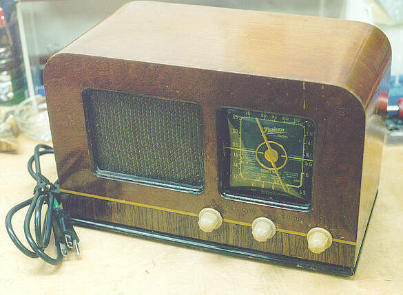
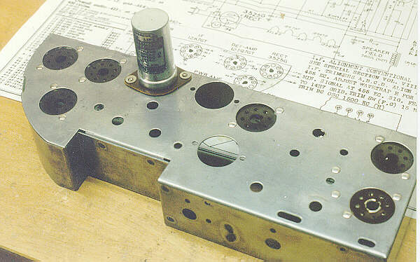
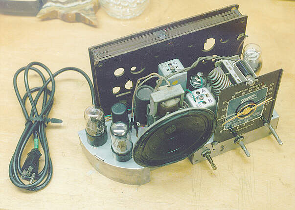
First, let's get a view of the patient. This Zenith is
a classic "black dial" set from the early 1940s. It receives
shortwave as well as AM broadcasts, using six tubes: 35Z5,
12SQ7, 35L6, 14H7, 12SA7, and 12K7. Walter thinks this is
a Model 6D512, but isn't positive. If anybody can confirm
the model number, please shoot us an email.
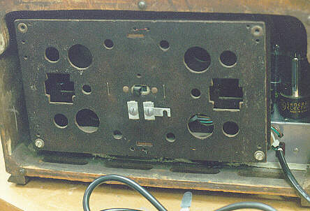
From the back, you can see the radio's loop antenna, wound around a rectangular
form. As part of the restoration, Walter installed a
three-wire grounded cord, using the third wire for the antenna
ground. The original cord probably had a spade lug at the plug
end to connect to the switchplate's securing screw.
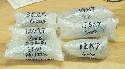
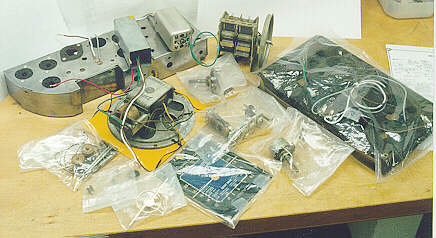
So, how do you start a total rebuild? Label, label, label. The first
law of restoration is to document every step of disassembly, and
label every part, so you can't possibly get confused when things go
back together. Here are the Zenith's six tubes, tested, packaged,
and labeled for reassembly.
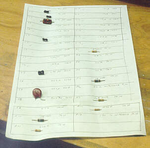
Below are some smaller components—capacitors and resistors—labeled
and attached to Walter's hand-drawn inventory sheet. Every
component is tested to confirm that it's still working
within the original manufacturer's specifications. The chart uses
the same component numbers (R1, R2, C1, C2, etc.) given on the manufacturer's parts list and schematic diagram.
This is what some call a "functional" or "practical" restoration.
New parts are used wherever needed, and no attempt is made to
disguise their newness.
If you want greater authenticity, there are things
you can do to preserve more of the set's original appearance
inside. Cloth-covered power cords are available from
Antique Electronic Supply, for instance,
and some suppliers may happen to have "new old stock" (NOS) parts.
Or, if original stock isn't available, you can hide new
components inside the cases of the old
ones.
That's the approach Walter used when remanufacturing his
prized Zenith 7G605 TransOceanic "Clipper" (here is a link to
my Clipper). He reused the
old electrolytic capacitor cases, taking out the old wax-impregnated
innards, inserting a fresh new unit inside each case, then refilling
each one with melted wax so that it looks just like the original.
You can read more about that technique in our recapping article,
Replacing Capacitors in Old Radios.
All of the original hookup wires were saved and reused, as well.
The next photo shows the chassis, stripped of most components and
meticulously cleaned of all grime and corrosion.
The photo also shows the schematic diagram,
essential for this kind of restoration. The schematic serves as a
guide to reassembly, and it also lets you doublecheck all
component values.
Many old radios have been repaired in the
past, and occasionally a repairer would use a component of the wrong value,
either by mistake or because the correct part wasn't available.
During World War II, American radio manufacturers had to divert all their
resources to wartime needs, and repairers had to use a lot of
ingenuity to keep some old radios going.
When all of the rewiring is done, the radio will need to be
aligned, just as at the factory. If you have never aligned a radio
before, you may want to practice on another set before
undertaking this kind of restoration.
Expect to spend a number of hours disassembling, cleaning, labeling, and
bagging up all the parts of your radio. As you disassemble the set, take
this opportunity to compare its actual construction to the more theoretical
view afforded by the schematic. Tracing the various circuits on the schematic
with colored markers can help you decipher it. When you're
finished with this stage, you'll have a collection of neatly labeled
parts, ready for remanufacture.
While everything is out on the workbench, now is the time to
recondition parts such as tuning capacitors and variable
potentiometers. Clean and lubricate every one as needed.
If you don't have the manufacturer's stringing diagram,
make a careful sketch of how to restring the cords on the
tuner pulleys. Don't trust your memory!
Some stringing setups are almost impossible
to figure out without instructions.
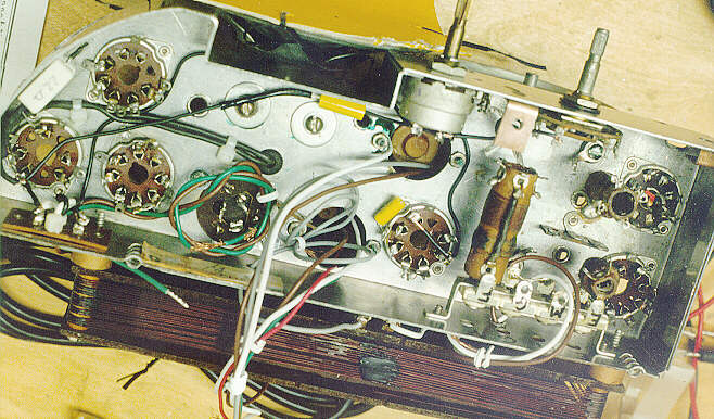
In the following picture, Walter has begun rewiring. Note the care
taken to route wires neatly and secure them with plastic ties.
There's no reason why a remanufactured radio shouldn't be as neat as
the original.
Another thing you'll want to do before taking the
radio apart is to take closeup photos and draw diagrams, if needed,
to guide you in rewiring. The actual layout of circuitry is often
quite different than the schematic, which is organized from a
theoretical viewpoint. Components that look close together
on the schematic may be far apart in the actual radio, and vice versa.
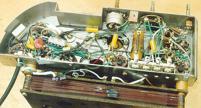
In the next interior shot, all rewiring is complete. Notice the roomy
layout—modern components are typically smaller than their older
counterparts. Your remanufactured radio will have a little
more elbow room inside,
and its components (capacitors, in particular) will be more reliable
than the originals.
Our final picture shows the completed project, just before
installing the remanufactured radio back in its cabinet.
You can see a couple of the new wires peeking up through
the chassis. On top of the transformers, which Walter also
rewired, you can see letters (A, B, etc.) which were written
on the cans to ensure correct rewiring.
A total restoration can be lots of work, but
there's no better way to learn how tube radios are put
together. And you'll end up with a radio that works reliably for many
years to come.
This radio construction project, including all descriptions, diagrams, photos, and the underlying electronic design, is published here for the noncommercial use of radio hobbyists. You may print and reproduce these project instructions for your personal use. Commercial use of this material is strictly forbidden.
|