Zenith Model 12-A-58 Console Radio (1936)


The regal Zenith 12-A-58 console was produced in 1936, during what many
consider Zenith's golden years. With a breathtaking cabinet design,
twelve tubes, and dual speakers, this model is eagerly sought after by collectors.
The 12-A-58 is sometimes called the "Baby Stratosphere,"
after the mighty Stratosphere, arguably the finest consumer radio
that Zenith ever produced. Stratospheres are as scarce as hen's teeth
and they sell for tens of thousands of dollars—if you can find one.
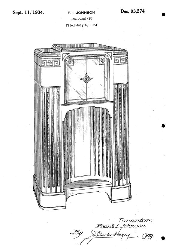
The 12-A-58 is quite similar in appearance and offers excellent performance
at a much lower price. Compare the 12-A-58 cabinet with the design patent
drawing for the 1000Z Stratosphere.
Notice the distinctive fluted side columns and
concave speaker opening. The Stratosphere cabinet has sliding doors to
conceal the dial, but both radios share the same bezel and
multicolored dial printed in blue, green, red, yellow,
and white. Lit from the edges, the tuning scale is truly a dramatic sight.
The 12-A-58's speaker grille has a graceful torch design. I have been told
that the torch commemorates the 1936 Olympic Games. A strip of inlaid
wood accents the cabinet's shoulders. My cabinet only has typical scratches
and scuffs, so I will touch up the boo-boos rather than strip and refinish it.
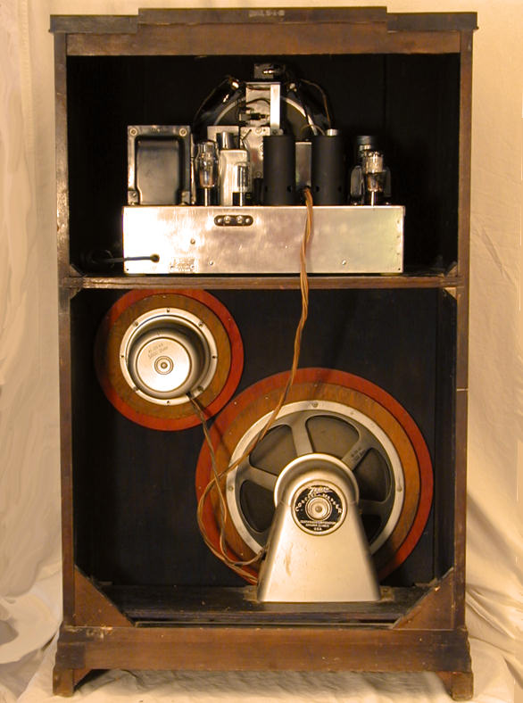
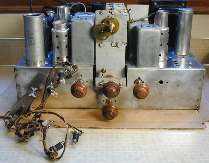
In the rear view, you can see the radio's two large speakers: a twelve-inch
speaker for bass tones and a smaller one for higher tones.
The speakers are connected to the chassis by a multi-wire cable. Since
the speaker field coils form part of the power supply, the speakers
must be connected when testing the radio.
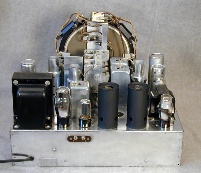
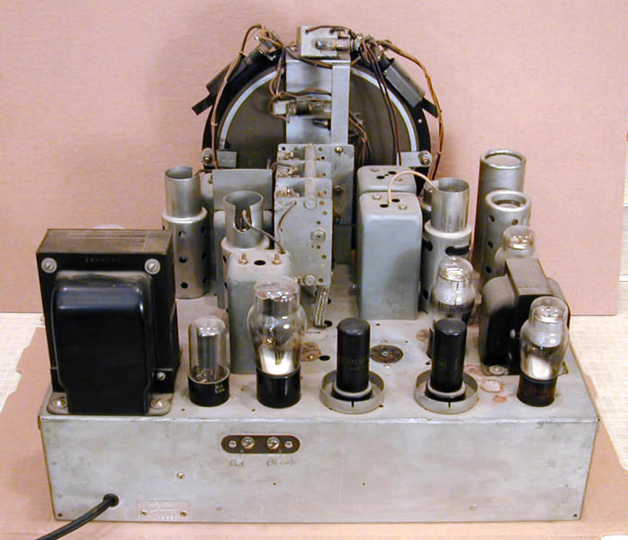
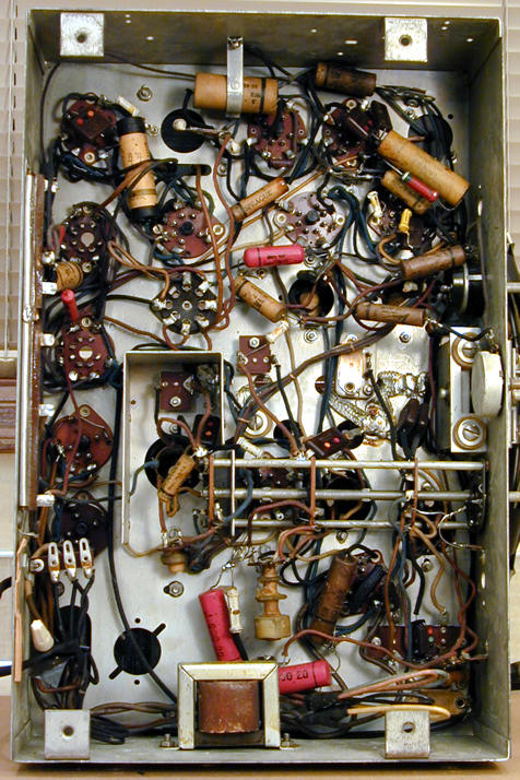
Here are front and back views of the chassis
before and after restoration.


Three minor things were wrong with the chassis as found.
The two audio output tubes were black metal rather than glass.
The radio was missing two black
metal chimneys that slip onto the output tubes. And, barely visible
behind the big power transformer, a newer can capacitor had been
installed during previous service.
I later found glass tubes, as well as chimneys and an
original capacitor case, to complete the authentic appearance.
I also cleaned up the chassis using metal polish.
I have seen a little debate about the black tube chimneys.
Output tubes don't need radio-frequency shielding, so the purpose
is presumably cooling, through ventilation and/or
heat radiation. Cooling is why metal tubes are painted black,
after all.
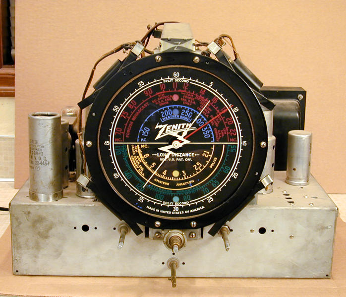
Dial Design
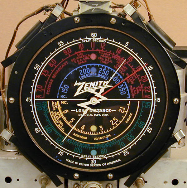
The 12-A-58 receives four frequency bands. A colored letter (A, B, C, D)
is lit from behind to indicate which band you have chosen.
The blue band covers 145-370 kilohertz, also known as "longwave"
(Weather in Zenith's labeling). This band is little used today.
The green band is BC (standard broadcast) from 550-1740 kilohertz.
The yellow band covers low shortwave frequencies from 2.0-7.0 megahertz
and the red band covers international shortwave broadcasts from
7.0-22.5 megahertz.
The white scale numbered 0-60 around the perimeter is a logging
scale for the red "split second" pointer. By recording a
shortwave station's log number in addition to its frequency, you
can more easily return to that exact spot, using the split second
pointer and fine tuning knob.
The dial is lit by four pilot lamps around the edges. If you restore a
12-A-58, carefully clean the edges of the dial glass where
this illumination enters.
There is an earlier version
of this dial with three layers of glass and eight edge lamps.
The lamps shine through colored filters to illuminate the selected band.
The colors on this dial are white, green, and purple.
I have been told that the earlier dial is rather dim. Perhaps Zenith moved
to the four-lamp design because it was brighter, as well as simpler
to manufacture.
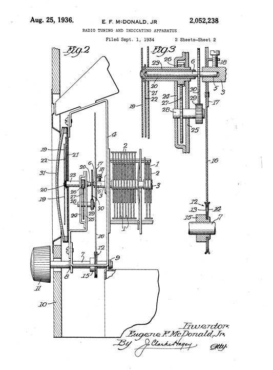
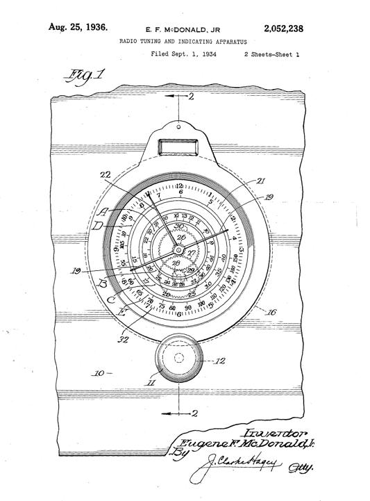
Dial Patent
Below are the engineering drawings for US Patent No. 2,052,238, granted
to Eugene F. McDonald, Jr., founder and head of the Zenith company.
This patent includes the split second pointer technology that
was employed in the 12-A-58 and other Zenith radios. You can read the
full patent,
with its description and claims, at Google's archive.
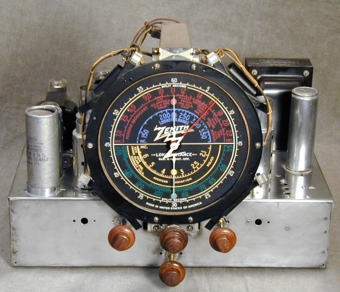
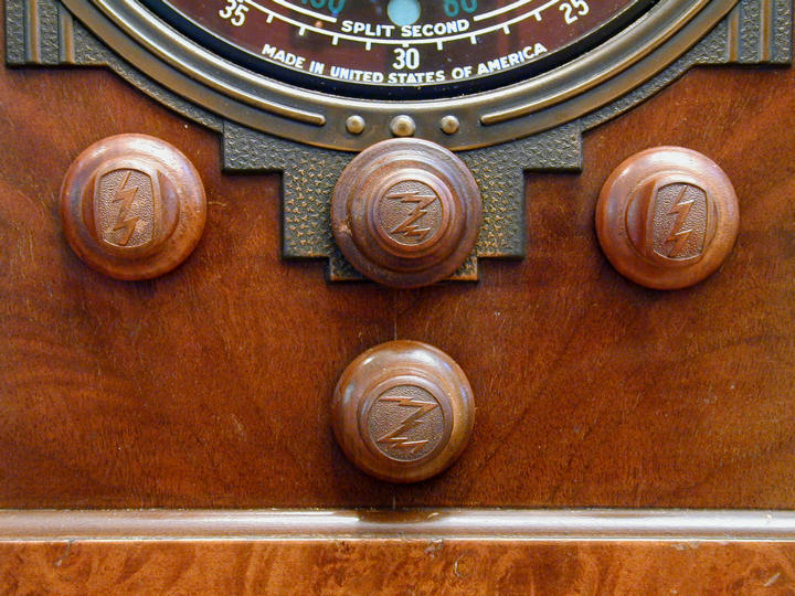
Controls
Here are the radio's controls. My 12-A-58 came with all of its
original wooden "Z" knobs.

The radio has concentric tuning knobs mounted on a double center shaft.
The larger knob turns the dial pointers quickly, while the inner
fine-tuning knob turns them more slowly.
To the left of the tuner knob is the bandswitch, which selects among
the four frequency bands. To the right is the power/volume control.
The tone control is located in the lower center.
Shadowgraph Tuning Indicator
Atop the dial in previous photos you'll
see a mysterious gizmo with the letter Z in the middle of two tapering
light bands. This is Zenith's Shadowgraph Tuner.

The visible face is a plastic piece with the Z logo
and the two tapered bands. A pilot lamp shines through a slot
in back of the metal case.
Inside is a thin metal vane which rotates based
on the strength of the signal being received. As signal
strength increases, the vane moves edge-on to the pilot lamp's rays, creating a thin
shadow at the center of the Z. If you tune to a weaker signal, or between stations,
the vane presents more of its surface to the lamp, creating
dark shadows equidistant from the center.
The Shadowgraph is quite sensitive, but it contains a delicate moving
part and demands a separate tube (type 6C5) to drive its circuit.
By 1939, Zenith had adopted the all-electric magic eye
tube, which performs the same function without the associated gizmo.
Philco and Atwater Kent also offered shadow tuning during the
years 1933-1938.
Another interesting tuning indicator is the ""Tunalite,"
used in my 18-tube Midwest DD-18 radio.
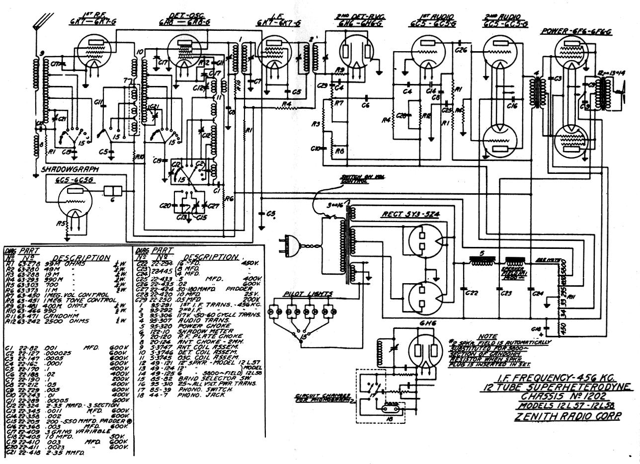
Tube Lineup and Schematic
Here are the 12-A-58's tubes and their functions.
|
Tube |
Type |
Function |
|
V1 |
6K7G |
RF amplifier |
|
V2 |
6A8G |
Detector/Oscillator |
|
V3 |
6K7G |
IF Amplifier |
|
V4 |
6H6 |
2nd Detector/AVC |
|
V5 |
6C5G |
1st Audio Amplifier |
|
V6 |
6C5G |
2nd Audio Amplifier |
|
V7 |
6C5G |
2nd Audio Amplifier |
|
V8 |
6F6G |
Power Amplifier |
|
V9 |
6F6G |
Power Amplifier |
|
V10 |
6C5G |
Shadowgraph |
|
V11 |
5Y3 |
Power Rectifier |
|
V12 |
5Y3 |
Power Rectifier |
The schematic diagram appears below.

If you are searching for the schematic in Riders, look up model 12-L-57.
Both models use chassis 1202.
Restoration
Here is what it took to restore this radio, beginning with
the electronics.
Electronic Restoration
This radio was excellent condition, so most of the
electronic restoration was straightforward, beginning with
capacitor replacement and cleaning of tubes and controls.
Replacing Capacitors
Since this website contains a detailed article on
capacitor replacement, I
won't repeat that material here. To make this radio
safe and reliable for regular service, I replaced all
of its electrolytic and paper capacitors with new ones.
In some special cases, I "restuff" all of the
old capacitors by hiding new ones in the original cases.
Since this radio had been partially recapped in the past,
probably in the 1960s, not all of the original cases
were available. Furthermore, I bought this radio to keep
and use, not to market as a museum piece, so
I simply installed new capacitors in place of the old.
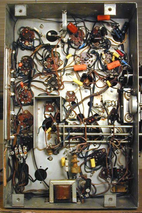
The next photos show the chassis before
and after recapping.
In the "before" photo, notice the two pink capacitors
near the bottom. These are plastic-coated paper caps from
the 1950s or 1960s, just as unreliable as the brown paper capacitors from
the 1930s. The rightmost pink one wasn't connected to anything.
Perhaps the previous restorer dropped it while working, and it
just sat loose in the chassis for the last four or five decades.
I mounted most of the new electrolytics on terminal strips under
the chassis after disconnecting the originals. A couple of smaller
ones were connected by their leads, as the originals had been.
I obtained an original electrolytic case to replace the non-authentic can
that was installed above the chassis in the 1960s; it is only for
appearance, not connected to any circuitry.
New capacitors are typically much smaller than the originals.
It's easy to find room for them!

After recapping, the radio played nicely, receiving on
all bands. There was still more work to do, but this was very
encouraging progress.
Cleaning Tubes and Controls
Cleaning is an important early step in every restoration.
I cleaned all of the tube pins and sockets as well as the
bandswitch, tone control, and volume control.
Prior to this, I had tested all of the tubes. All of them were
good, which is not uncommon in my experience.
Cleaning tube pins and sockets is easy. One tube at a time
(so you don't mix them up),
remove the tube and shine up the pins with very fine sandpaper.
Then plug and unplug the tube in the socket several times.
If the tube has a glass envelope, grasp it by the base
rather than the glass.
To clean the bandswitch, spray a small amount of DeOxit or
similar electronic cleaner on the
contacts, then work the bandswitch through all bands several
times. Don't splatter cleaner all over the chassis, and
carefully wipe up any excess.
Next comes the tone control, which is easily removed without disconnecting
its leads.
Like many controls of this vintage, this one is well sealed
in its case. You loosen the case by gently bending up a few
flat tabs on the shaft side, then pulling the case off. I had
previously removed the mounting nut from the front of the chassis,
allowing the control to be slid back to hang by its leads.

Once the control was open, I applied DeOxit inside, then turned
the control back and forth all the way several times before wiping off
the excess and reassembling the control.
The volume control changed the volume acceptably, but it was very stiff
to move, due to dried lubricant inside, so off it comes.
As the next photo
shows, this control was blocked from behind by a small terminal strip and required the
unsoldering of six leads before it could be slipped out. In addition
to three leads on the top, you need to unsolder two leads on the
integrated power switch and one lead connected to a tab on the
very front of the control.

In the next photo, all six leads have been carefully unsoldered.
I also loosened the screw holding the terminal strip and rotated
the strip aside to make room for the control to slide backward
out of the chassis.

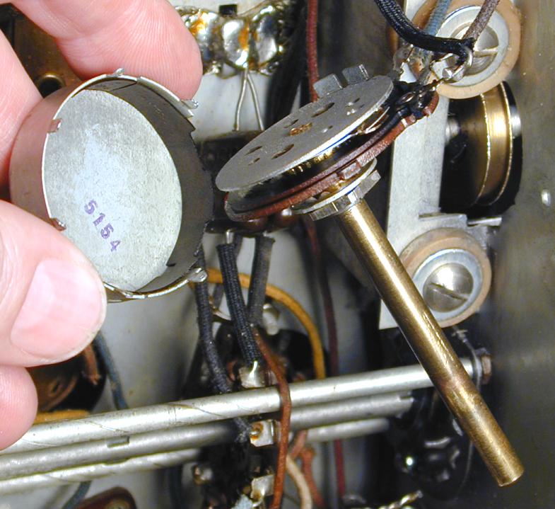
This case is secured by tabs on the front (shaft) side, but
you don't bend these tabs straight up as with the tone
control. Instead, each tab is gently moved sideways, using a thin
screwdriver or knife blade to free the control from its case. When
you reassemble the control, these tabs will snap back into their
slots. Here is the disassembled control.

These innards of this control are different than what we saw before.
The tone control had a simple metal wiper moving on a
track of resistive material, a design still used to this day.
In this control, a moving nonconductive pad presses a flexible metal
strip against a stationary outer ring of resistive material.
You can see the brown pad in the previous photo.
Electrical contact is made only where the strip is pressed down.
As the flexible strip contacts the resistive track at different
points, the resistance of the potentiometer changes.
In order to move smoothly,
the pad needs a thin film of lubricant between it and the flexible strip.
Over time, the original grease had dried out and solidified. To cure
the stiffness, I cleaned the pad and strip and applied a small
amount of lube. Now the control turns like butter and
shouldn't need attention for years to come.
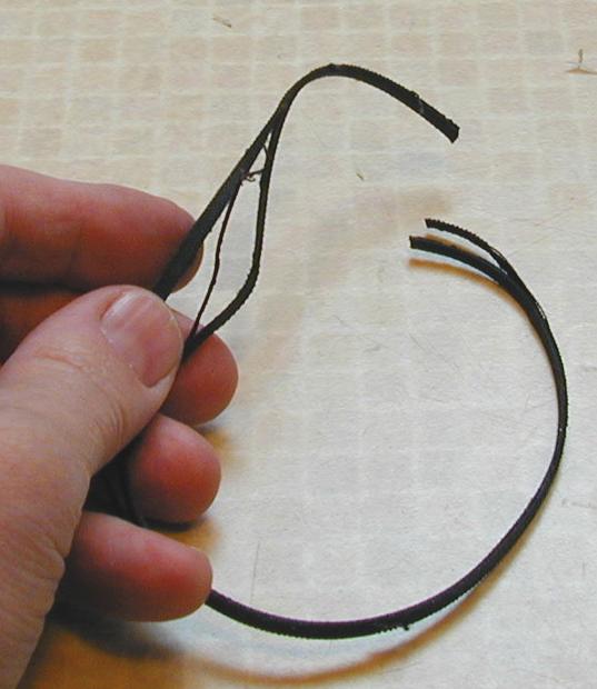
Replacing the Tuner Drive Belt With O-Ring Material
The 12-A-58, like many Zenith radios, used a flat, coated fabric belt running
over brass pulleys to drive the tuning mechanism. Over time, the belt frays
and delaminates, slipping on the pulleys and failing to move the
tuner. This photo shows the original damaged belt after I cut
it off the pulleys. It is frayed on the edges and its layers
are separating.

Original flat belts are no longer available. The usual solution
is to make a new belt using 1/8-inch round rubber O-ring material,
available from suppliers such as
McMaster-Carr. You cut the O-ring stock to the correct length
and super-glue the ends to make a circular belt.
What is the correct length, you might ask? Measure your old belt and
cut the rubber a bit shorter, perhaps 1/4 to 1/2 inch. Buy enough
O-ring material to allow for two or three tries, in case you don't
get the length right the first time or botch the super-glue joint.
Use fresh super glue (cyanoacrylate) and hold the ends of the
O-ring firmly together for one minute while the glue sets.
After an hour or so, any excess glue around the joint will
appear as hard white material, which you can smooth off using
a fine file.
A Tale of Two Pointers
Some radios provide enough access that you can replace the
belt without removing anything else. Not so with the 12-A-58.
There is scant space between the back of the dial and front
of the tuning capacitor, and other components such as pilot
lamp brackets make it impossible to reach the belt without
tools such as long forceps and tweezers.
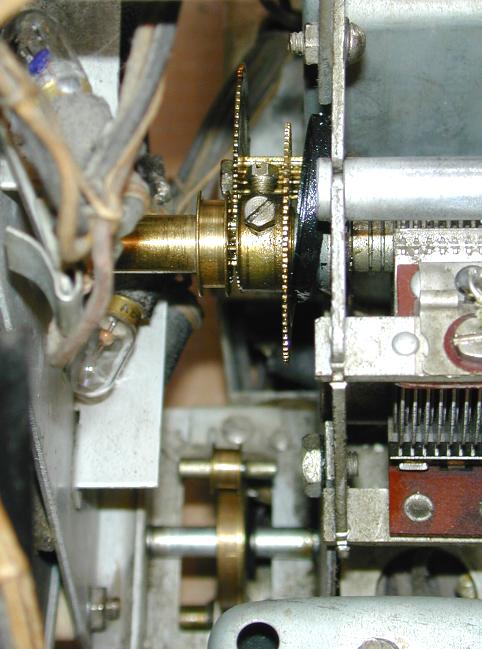
Here's a view of that space on the unrestored chassis. The ragged
old belt has been cut off, revealing the top pulley and associated
gears. Farther down in the murky depths are the two other pulleys.
To get reasonable access to the belt, you must remove the dial.
This also lets you clean and lubricate the tuning
mechanism, which is often stiffened up with dried lubricants.
The first step is to remove the dial pointers.
On my radio, the white main pointer with the Z emblem was
easily removed with a gentle twist and a pull.
The red split second pointer was more recalcitrant.
At first, I tried dripping some
oil down the pointer shafts, then levering it off.
The pointer refused to budge!
If I had applied more leverage, I might
have broken the dial face, deformed the tuning mechanism, or
both.
I then wasted a lot of time trying to replace the belt without
removing the dial. The cramped space made it fiendishly difficult
to place the belt and glue it. What's worse, the tuning mechanism
seemed to bind up in a couple of spots, even with a new belt that
should have worked. Three tries later, I threw in the towel.
After soliciting some advice from experts in the
rec.antiques.radio+phono newsgroup,
I tried again to remove the red pointer.
I first turned the tuning capacitor so that its vanes were completely
meshed. Then I applied some heat to the pointer collar with a soldering iron,
in hopes of expanding it on the shaft.
Reaching behind the dial with one hand, I firmly gripped
the main tuning shaft while twisting pulling the red pointer's
collar. It gradually came free!
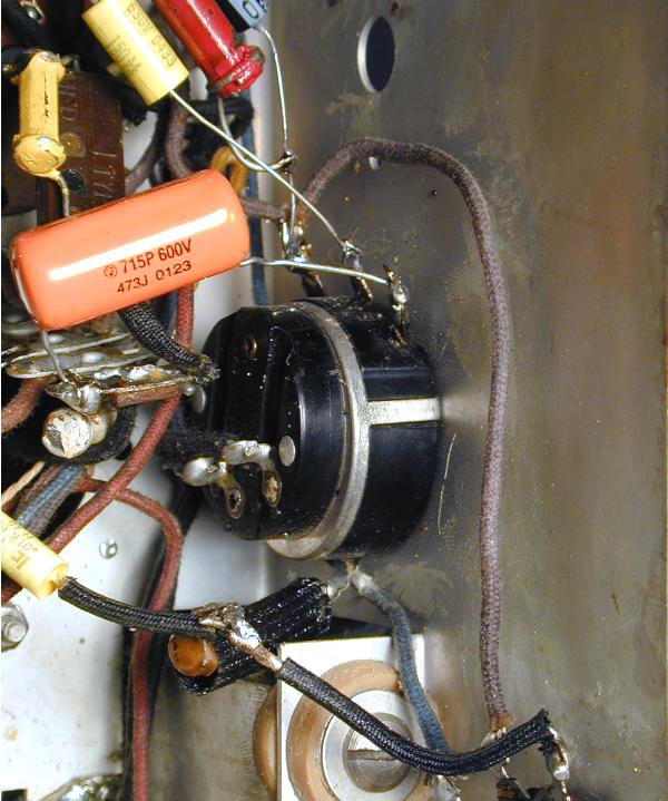
The next photo shows why this pointer is not easy to remove.

Notice the heavy split collar that extends down the tuner shaft.
This makes for a very tight friction fit! The black plastic washer
goes between the pointer and the dial, concealing the tuning shaft
hole in the dial.
Removing the Lamp Harness and Dial
With the pointers off, the next step is to pull the dial and
the pilot lamp harness.
My 12-A-58 has eight pilot lamps: four to illuminate the dial
and four more to light the band indicators. The lamps and
the Shadowgraph tuning indicator are connected
by a long wiring harness.
Start by removing the two mounting screws from the Shadowgraph case.
As soon as you have slid the case aside, put the mounting screws back
in their holes for safekeeping.
Now you can slide each pilot lamp off its mounting tab
and carefully pull out the entire harness.
The dial can be freed by removing three screws above the chassis
and a split washer under the chassis.
The next photo shows the chassis with the dial removed and the
pilot harness off to the left.

The three dial mounting screws are clearly visible in the previous
photo. A pair of screws goes into the chassis on either side of the
main tuning knob. A third, smaller screw is located up and to the
left of the topmost brass gears in this view. It passes through
the top of the tuning frame and is secured with a small nut.
The split washer under the chassis is shown in the next photos.
It secures the rear end of the tuning knob shaft.
If you compare the photos, you'll see that I did some minor surgery
on the chassis. The round O-ring belt is thicker than the original
belt and it will rub hard against the chassis unless you cut or file
a little notch, as I did. This may not be needed on other Zenith models,
but it's essential when using a round belt on the 12-A-58.
I removed the split washer by pressing its ends apart with two small
screwdrivers. This lets you slide the tuning knob assembly forward,
just far enough to clear a metal stud that projects from the front
of the chassis.
The stud has two purposes. It runs through a hole in the bottom of
the dial frame, aligning it so that the dial markings won't be cockeyed.
It also acts as a stop for the tuning knob mechanism. After the tuning
shaft is pulled past the stud, you can slide the bottom of the dial
frame forward, clearing the stud and allowing the entire dial to come off.
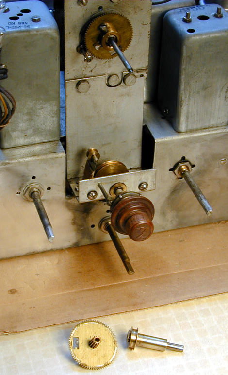
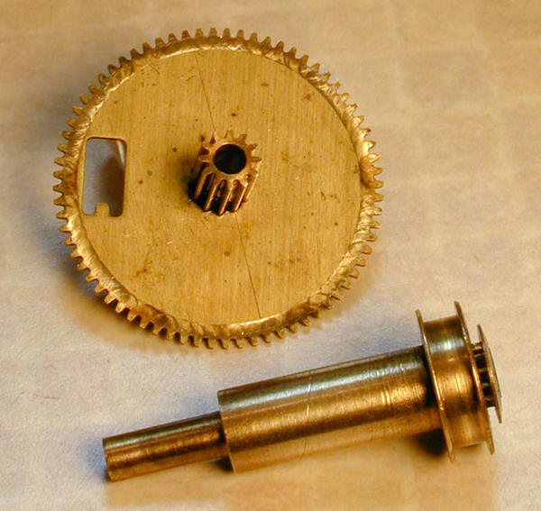
Freeing the Tuner and Replacing the Belt
With the dial out of the way, we have easy access to the tuning
mechanism. In this photo, I have removed two of the top tuning gears.
They come off as a pair after you remove a little nut from the
front of a chassis stud. This nut secures the large gear, which
is meshed with the rear of the smaller gear. The small gear, as you
can see, also includes the top drive belt pulley.

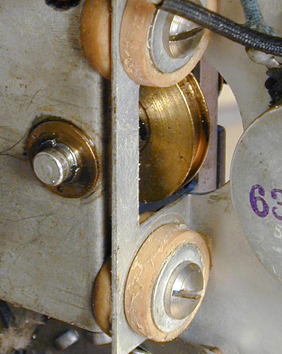
This photo also gives us a clear view of the three pulleys. The belt
goes around the large pulley at the bottom and the small one at the
top (the small one is removed in this view). To the left of the
big bottom pulley is a small tensioning pulley, mounted on a flat
spring; the belt passes inside this pulley.
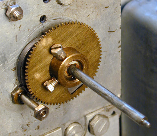
Looking more closely, it's obvious that the large gear was scuffing
badly against the rear lip of the smaller gear.

When I got this radio, the tuning mechanism was completely frozen.
Lubrication had freed it somewhat, as in many cases, but no
amount of lubrication will cure a problem like this. Fortunately,
it was easy to solved. Adding a little washer between the tuner
frame and the rear face of the large gear put it back into
alignment with the small gear.
This mechanism also includes a "return spring," which
tightens as you turn the tuner clockwise and unwinds as you
turn it counterclockwise, giving the mechanism a little help
on the way back down. I have been told that the spring helps maintain
correct tension in the mechanism, essential for fine tuning
in high shortwave frequencies.
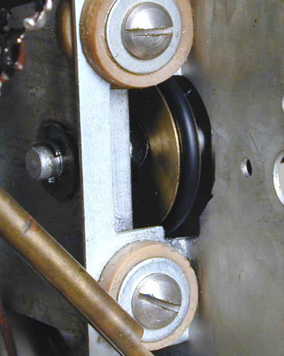
I noticed a couple of small spots where the rear edge of the spring
had been scraping on the tuner frame. The next photo shows
scrape marks on the tuner frame and the black spring peeking out from behind
a large gear.

I lightly polished away the scrapes with a Dremel tool, then sparingly lubricated
the spring and reassembled the mechanism. When all of this was done,
the tuning mechanism moved freely at last. If I manually cranked it all the
way counterclockwise and then let go, it spun back down like a top!
Now it was a simple matter to cut the O-ring material to length, thread it through
the pulleys, and glue it.
With the belt in place, the added drag from the tensioner pulley and the
lower tuner mechanism slowed things down, but the tuner still tended to creep
back down by itself when returning from the far counterclockwise position.
I solved this by very gently tightening the nut that holds the large upper gear on its stud
(this is the one to which I had previously added a washer to align it with
the small gear).
After replacing the dial and pilot lamps, I had a working
radio again—this time with a tuner that moved smoothly all the
way up and down.
Alignment
Aligning this radio took only about ten minutes. This photo shows the
setup, with my trusty old EICO 324 signal generator next to the
Zenith, along with a Grundig YB400 digital receiver which is used to check
the signal generator's settings.

The 12-A-58's IF (intermediate frequency) is 456 kilohertz.
My digital radio doesn't receive 456 KHz, but it does receive
912 KHz, a harmonic. After setting the signal generator's dial
to 456 KHz, I connected its output leads to small loop of
wire placed next to the digital radio, then tweaked the generator
until the signal appeared strongest on the digital set. This ensured
that the generator was right on the money. You won't have to double-check
the setting if you're using a modern digital generator, of course.
Using a similar procedure, I made all of the adjustments for the
radio's different bands. After I
was done, the radio played beautifully, with the
dial pointer tracking each station's frequency exactly.
Cabinet Restoration
I haven't started the cabinet restoration yet, so that will be
another story.
To be continued . . . .
|