Emerson Model 1232 Television-Radio (1956)


Emerson's Model 1232 was a charming entrant in the 1950s mini-TV race. General Electric launched the
competition in 1955 by marketing the first portable, metal-cased portable television. Other manufacturers
quickly followed suit, designing even smaller sets housed in colorful cabinets.
Many 1950s "portables" are hefty. My RCA 14-S-7070G weighs
nearly 30 pounds and measures about 12 inches by 14 by 16. With a 14-inch screen, it makes
a nice tabletop set, but it's too big and heavy to tote around without grunting.
The Emerson 1232 is considerably smaller. With an 8-inch screen, it weighs just over 20 pounds
and measures only 7.5 inches by 12 by 12. The carry handle can be swiveled down to serve as
a tilt stand, and its built-in telescoping antenna (broken on mine) can be popped up from
the rear of the case.
Another selling point is the Emerson's built-in AM radio. With a TV, radio, and phonograph
input, this set could serve as a real mini-entertainment center. There's no doubt about when
this set was made. A build tag on the chassis is stamped October 2, 1956.
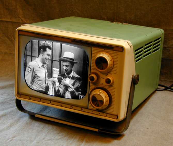
The first photo shows the set after restoration. The picture quality is excellent,
nice and sharp with good brightness.
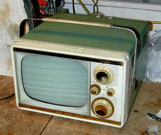
The second photo shows the set before restoration. The TV received all stations well and
had good sound with a strong raster, but it was unable to synchronize horizontally.
This set used only 15 tubes, including the CRT. That's a comparatively small number, especially
since two of those tubes were devoted to the radio. Many 1950s televisions used 20 or more tubes.
Electronic Restoration
I knew that this set would need significant cleanup even before I removed the case. Although the
cabinet exterior wasn't too dirty, the whole TV smelled strongly of cigar smoke and grease. The
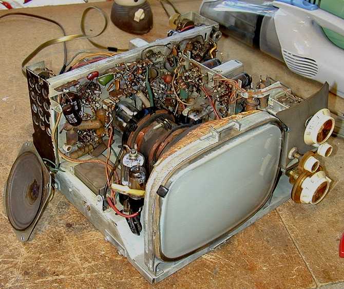
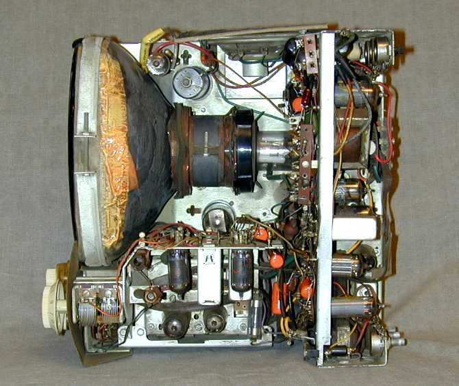
next photo shows the unrestored chassis, covered with a thick layer of stinking grime.
Cleaning up this mess took hours. I began by brushing off as much dust as I could, then
went to work with toothbrush, Q-tips, and paper towels. To loosen the grime, I used
"Goof-Off 2" and rubbing alcohol. I also cleaned all of the controls with DeOxit gold spray.
Now the chassis was ready for electronic restoration. As the next photo shows, someone had
previously replaced a few paper capacitors with more modern ones, but there were quite a few
of the old, unreliable paper capacitors still in place.
Routine capacitor replacement is covered in Replacing Capacitors
in Old Radios, so refer to that article for advice on recapping.
By the time I finished
replacing the paper caps, the TV was playing better than ever, but the horizontal hold
problem persisted. Lack of horizontal sync usually indicates that the horizontal oscillator
is running at the wrong frequency. A quick adjustment of the horizontal frequency coil
cured that problem for good.
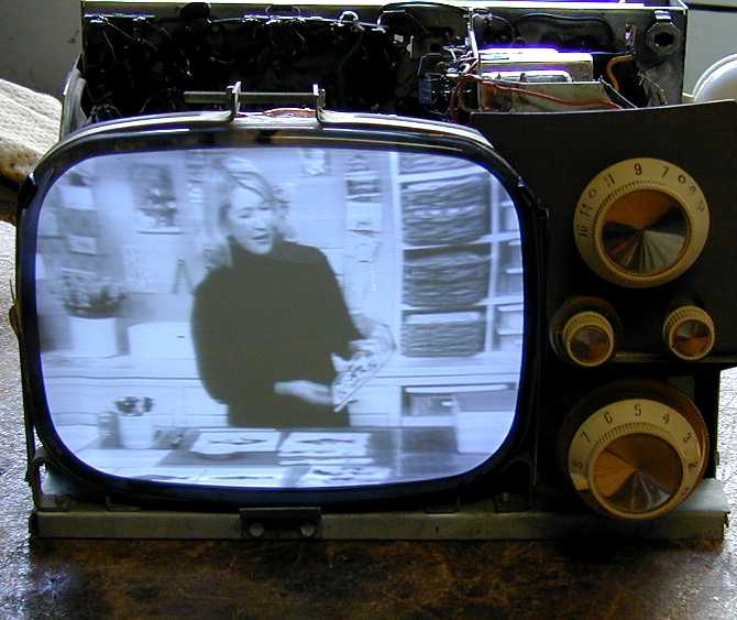
It's always an exciting moment to see the first good picture on an old tube TV. Here's a photo
of the TV at that point, showing a Martha Stewart episode.
After tweaking other adjustments such as vertical height and linearity, I declared victory.
This was the easiest TV restoration I had done up to that point. Of course, it helped that someone
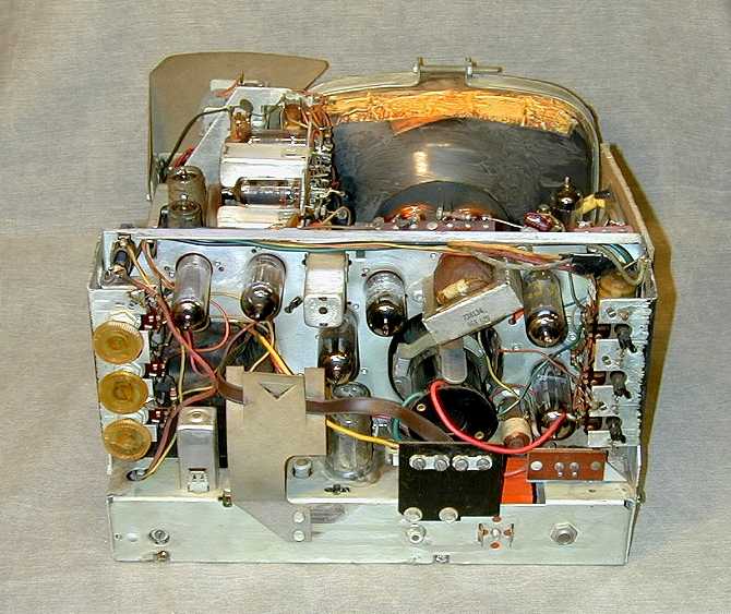
had previously replaced several components! The next photo shows the restored chassis
from above. The new capacitors are colored orange and yellow.
This view reveals how the designers incorporated a radio into a TV. The tuning
capacitor is at lower left. The radio tubes and transformer cans hang downward
from a small subchassis near the lower center of the photo. I'm not sure whether Emerson marketed
a version of this TV without the radio, but that could easily have been done, looking
at how the radio circuitry was neatly slipped into the TV chassis.
When you switch from TV to radio mode, the picture naturally goes dark. I believe that all
of the TV tube filaments remain heated during radio operation, however. If you power up
the set in radio mode, then switch to TV mode, the picture appears instantly, with no warmup time.
In later years, some manufacturers used this technique to make a tube TV with "instant on," just like
a solid-state set. When you turned the set "off," all of the tube filaments remained lit, so when
you turned it back "on," the picture appeared instantly.
Tube manufacturers must have loved those sets!
Keeping the tubes heated at all times certainly contributed to shorter tube life.
I owned such a TV in the 1970s. When I wanted to turn it off, I simply unplugged the power cord. That's not
such a big factor for this TV. When the radio is operating, the TV tubes are
heated. But when you turn off the set, everything is powered down.
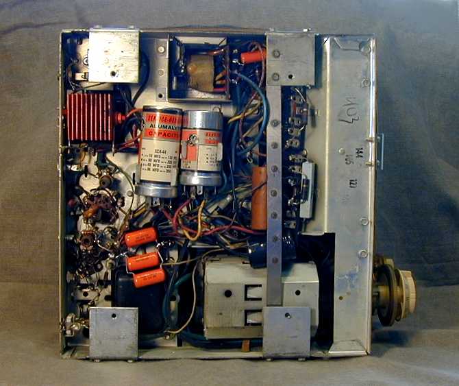
The next two photos show the restored chassis from the back and underside.
Three of the four
electrolytic capacitors had been replaced recently. Since the TV's voltages tested normal,
I left these in place, although I'd normally replace them as a
matter of course. The three orange drop capacitors
near the center of the photo
actually constitute one component. I didn't have a .15 mfd capacitor on hand, so I combined
three .05 mfd capacitors in parallel to equal .15 mfd.
The underside view also shows the selenium rectifier. It is the stack of orange metal plates
in the upper left corner. If I decide to use this set regularly, I will replace it with a modern
silicon diode and dropping resistor, to improve reliability.
Final Thoughts
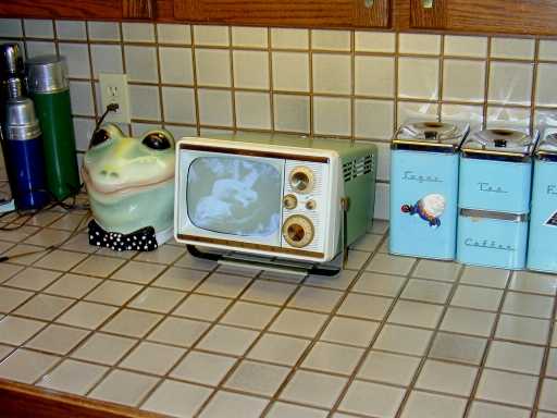
The final photo shows the little Emerson playing happily on our kitchen counter. (Don't ask me
what's in that picture. I think it was some kind of nature program.) Given the small
size and the combination of TV and radio, I bet that many of these were used as kitchen sets.
Small tube TVs in metal cabinets tend to run hot, and this one is no exception.
Some sets of this
type tend to work beautifully for an hour, then develop problems (often with
vertical or horizontal hold), after key resistors or other components change
value from the heat. If you don't feel like hauling the TV back onto the workbench,
you can try putting a small muffin fan next to the ventilation slots, to keep it cooler.
Some years after I restored this set, it was purchased by someone who presented it as
a gift to a retiring Emerson executive.
If you are looking for a tube TV to restore, I'd start with something a little less cramped as a first
project. The component layout is sensible, but it's necessary
to partially disassemble the chassis to reach a few of the paper capacitors. Most console TVs
and large tabletops are much easier to service.
Be sure to check out our TV Gallery and Restoration section for
other TV and radio restoration chronicles. An even smaller tube TV is the
RCA 8-PT-7012.
|