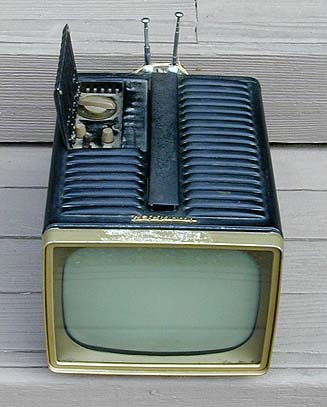
RCA 8-PT-7012 (8-PT-7030) Television (1956)


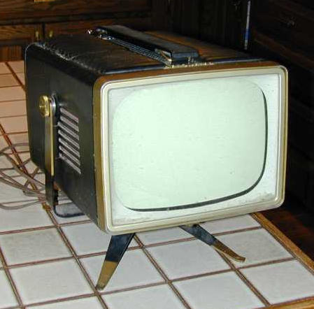
A delightful "mini portable" TV from the mid-1950s, the RCA
8-PT-7012 is about the size of a lunchbox, although it weighs
considerably more. The first photo shows the TV as found
at a flea market.
Although the top of the screen bezel was gummy from old tape,
the cabinet was in good shape, with no dents or paint scratches.
The television had no picture at all. The sound was excellent,
however, and the tuner seemed to bring in all stations quite clearly.
For the price of $17, I figured it was worth the risk.
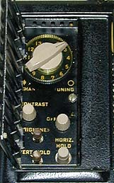
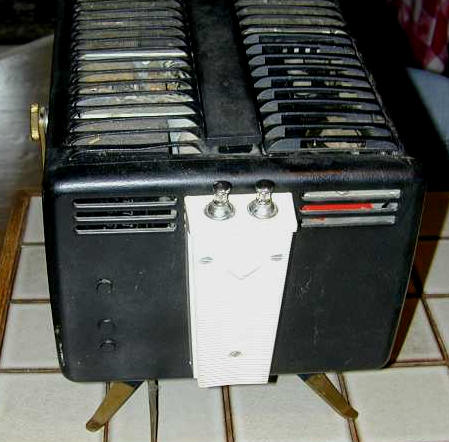
The next photo shows the tiny control panel, which hides under
a hinged door in the cabinet's deeply vented top.
With an 8-inch (diagonal) screen, the entire TV measures only 12 inches deep by 6
inches high by 9 inches. The designers showed incredible ingenuity in packing a
fully functional tube television inside such a small package!
Service Manual
I restored this TV using the SAMS service manual, which I obtained from
Antique Electronic Supply. Several
years later, a fellow collector sent me a copy of the original RCA factory
manual, covering models 8-PT-7010 through 8-PT-7034.
The factory manual is very thorough. I wish I'd had it when I restored
this set. It is scanned as an 8-megabyte PDF file, so you'll need a fast
connection to download it. Click the following image to view the manual.
To save it, right-click the image and choose Save Target As.
First Impressions
The first step, as always, was to remove the chassis from the case. This is done by
placing the TV screen down on a padded bench. Remove the small setscrew from the
bottom of the screen bezel. Remove both Philips screws from the handle on top.
Remove three screws from the antenna housing in back and carefully detach the antenna
leads. Remove both tuning knobs and the small knobs for contrast and power/volume. The other
knobs can stay on. Remove three screws inside the control panel; note that two of them
are hiding under the hinged cover to the left. Now you can gently slide the cabinet
upward.
The chassis is covered with four cardboard dust shields, as shown in the
next photo. These shields also prevent unwary fingers from touching bare leads inside.
The cardboard shields are held in place by the same screws that hold the
subchassis rails together. Loosen those screws just enough to slide out
the shields, then tighten them back up.
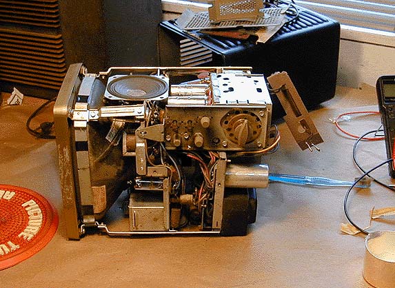
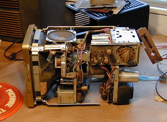
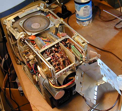
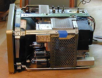
The next two photos show how the chassis cleverly slides apart along little
rails, providing access to every component while connecting the subchassis by extension cables.
There are two subchassis. The front one contains the sweep (horizontal and vertical)
circuitry and the rear one contains the RF/IF and power supply circuitry.
The first photo shows the chassis in its normal state. The second shows the RF/IF
subchassis loosened and slid backward for access.
The front subchassis also can be loosened from the rails and slid backward,
although I didn't find that necessary in this restoration.
As a result of the design, it's actually possible to operate the
TV in its "unfolded" state.
Caution! I must warn inexperienced restorers that operating a bare-chassis tube
TV can be dangerous if you poke your fingers or a tool in the wrong place. Use caution and
common sense at all times.
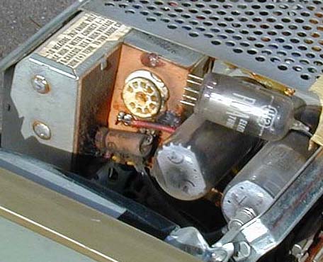
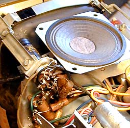
Not surprisingly, the inside of this cramped television gets hot during operation. When I opened
it for cleaning, I found melted wax from the flyback transformer running down one side of the
sweep chassis. The next photo shows how wax had not only run out the cracks of the flyback transformer
cage, but even seeped out through the pins of the 1V2 high-voltage rectifier tube socket.
In the previous view, the top of the TV is toward the left of the photo.
Directly below the flyback cage are the horizontal damper and output tubes, whose
heat played a part in liquifying the flyback's wax over time. Both of those tube
sockets were coated with a healthy amount of charred wax and crud.
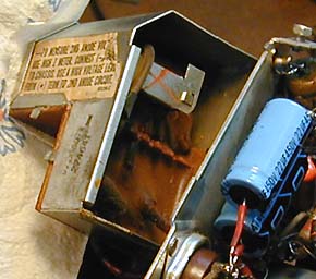
Later in the restoration, after I had replaced some electrolytic capacitors, I opened
the flyback cage and found wax filling the lower part of the
cage, which contains the high-voltage rectifier socket.
This looked a little ominous, so I queried the resident TV experts in the rec.antiques.radio+phono
USENET newsgroup, asking whether I should remove the wax or simply leave it alone. The consensus
seemed to be that the wax wasn't doing any harm, so I buttoned the cage back up and proceeded with other work.
Incidentally, I got loads of good advice from rec.antiques.radio+phono folks throughout
this project, particularly Bill Sheppard and Eric. Thanks, guys! I would not
have been able to finish this project without your help.
As soon as I got the schematic, I checked the placement of all tubes, in case
one had been mixed up in the past. More than once, I have been tripped up by
a radio that simply had the wrong tube in a socket.
Most tubes tested OK and were in the right place. One of the vertical
tubes, however, seemed to be wrong. Where the schematic called for
a 6CG7, my TV had a 6CM7.
Gosh, could it be this easy? Maybe with the right tube in place, the dead
screen would magically come to life! I quickly borrowed a 6CG7 from another working
TV and popped it into the socket.
Nope. The TV behaved exactly as before, with good sound and a dead screen.
Guess there's no such thing as a free lunch, after all. I proceeded with
cleanup and ignored the tube for the time being.
Capacitors, Capacitors, Everywhere
The "other work" consisted mainly of replacing capacitors,
as in all restorations. This TV used a lot of paper capacitors
and some of them were
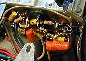
crammed pretty closely with other components. The next photo
gives a view under the 6CM7 vertical tube. Note how the components are
layered and even wrapped around each other, to keep things compact.
When you encounter a component cluster like this, some times it's
simpler to replace everything, rather than torture yourself trying
to preserve a few original resistors. Do yourself a favor: If you
have to disconnect one leg of a component, you may as well disconnect
the other leg and put in a fresh one.
The next view shows the interior of the RF cage, which is located at the
rear of the chassis. This TV uses wafer-type switches in its tuner,
a cheap solution compared to more expensive sets, but understandable
given the need to minimize cost and save space in a television of this
type.
Although the tuner mechanism looked clean as a whistle, I cleaned
it carefully with DeOxit, as long as I had it open.
Incidentally, you can
read all about recapping in the article Replacing
Capacitors in Old Radios and TVs. The basic techniques are the same for
radios and TVs.
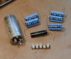
The next photos show how I replaced the big can capacitor, a multi-section
unit that contains four electrolytics of various values.
Sometimes, you can remove the innards from the old can and
hide the new electrolytics inside, to preserve authenticity.
In this case, I discarded the old can and mounted the new electrolytics in
its place, using a terminal strip to secure all of the leads. The TV won't
look exactly like before, but it will work fine, just the same.
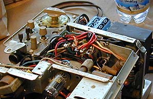
In the next view, you are looking at the new terminal strip under
the RF/IF chassis, holding the leads for the new capacitors, which
are strapped in a tight bundle occupying the space where the
can used to live.
After the electrolytics had all been replaced, I spent some time checking
voltages around the receiver, comparing them to the values given in
the schematic. The basic power supply seemed healthy, but the
TV did not show the indicated amount of "boost" voltage, producing
less than 300 volts where the schematic called for 480 volts. Since I
hadn't finished replacing capacitors, I made a note of this and
continued replacing things.
Here is another view of recapping work. I did my best to wrap the new components
exactly as the originals had been installed. Overly long leads can cause problems in some circuits, and there's no room for lazy-man's work in this TV, anyway.
Here is a view underneath the 6CM7 tube. We saw this cluster previously,
before recapping, but from a different angle.
About midway through the recapping process,
I was delighted to see the formerly-dead picture tube light up at last!
Seeing light on the CRT relieved my fears that the picture tube was
completely dead. Where there's light, there's hope!
The bad news was that it only showed a bright horizontal line, the
classic symptom of problems in the vertical circuits. Given that,
I went ahead and not only replaced all the capacitors on the sweep
chassis, but checked every resistor and replaced several whose
values were suspect. I believe that every component visible in the
previous photo is new.
The next photo shows part of the RF/IF chassis after recapping. Thank
Heavens for those tiny yellow capacitors, which are typically much
smaller than their original paper counterparts. This shot also gives
you a good idea of the component density in this chassis.
A Tale of Two Tubes
When I finished recapping the whole television (whew!), it still
showed the same symptoms: gorgeous sound and precise tuning,
but only a bright horizontal line on the picture tube.
Now began a long stint of testing voltages all around the chassis
and comparing them to the schematic. I also spent considerable time
checking my work, to make sure I had not miswired any components or
installed something of the wrong value.
In the course of this checking, I noted again several discrepancies between
the schematic and my set. When I ordered this schematic, I got a copy of
the Sams folder for model 7030/1/2/4, along with a copy of the Sams index
indicating that my model—7012—is also covered by that folder.
I had taken it on faith that my set should exactly match the schematic, but
that was not the case. Several capacitors and resistors differed in value.
Some of the differences were not large, such as a 3.9K resistor instead of a 5.6K.
Others were bigger, however, such as a .22 mfd capacitor instead of .047 mfd.
I began noting all these differences, in case they were important. All of the
differing components looked original, but who knows, perhaps they had been
replaced by a very neat worker who changed things for some reason.
More troubling were some discrepancies in voltages. At tube V6, the
vertical output tube, I tested 0 volts on pin 7 rather than -20 as
specified, and 175 (!) on pin 6 where 50v was specified.
Those are bigger variations than I would expect on a set that had
been completely recapped.
Looking more closely at the schematic, I discovered that my tube V6 was
not even connected in the same way as the schematic showed. What the heck
was going on here?!?
Slowly, a little light bulb went off in my head, as I remembered replacing
the 6CM7 tube with a 6CG7 at the beginning of this project. Could that be
the answer?
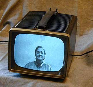
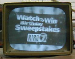
Sure enough, when I put the 6CM7 tube back in, the picture immediately
popped out and was easily adjusted to near normal. The next photo shows
the TV's reception at this stage.

The brightness was poor, the focus wasn't great, and the picture had
a wicked horizontal slant, but I had a viewable picture for the first
time in this project.
Adjusting the Ion Trap
All right, model 7012 is clearly not identical with the models
shown in my schematic. Cussing myself for working so long with a wrong tube in place, I proceeded
to try to improve the picture. Once again, the rec.antiques.radio+phono
folks came to the rescue.
Tests revealed no obviously bad components in the brightness and
contrast circuits, but I went ahead and replaced a couple of resistors
that were somewhat out of range. The brightness was still weak,
however. The picture was barely watchable even with the brightness
control turned up all the way.
Eric, who has worked on these sets before, suggested that I adjust the ion
trap magnet, a common cause of dim picture. An ion trap was a new concept to
my beginner's mind, so I pulled out one of my old TV books for an
explanation.
In a nutshell, the ion trap magnet prevents ions
from the picture tube gun from striking the screen's inner surface,
thus avoiding damage known as ion burn. The book said, as Eric had suggested,
that a misadjusted ion trap would make it impossible to obtain sufficient
brightness on the screen no matter how the brightness control was adjusted.
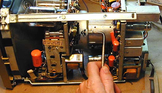
On this set, the ion trap is adjusted by manipulating a little metal collar
around the neck of the picture tube. A stiff paper sleeve is provided to
let you do this without poking instruments down into the narrow space
between the picture tube neck and its surrounding metal shield. The
paper immediately broke when I tried to move it, however, so I ended up
poking a long crooked-neck tweezers in far enough to reach the metal collar.
Sure enough, when I pushed the collar in, the picture immediately grew brighter.
Working a bit at a time, I adjusted the trap so that
the picture had normal brightness.
Adjusting the Picture
Now I needed to center the picture vertically and horizontally,
and adjust the height and width.
This is best done with a TV test pattern, but at this early stage in my
TV fixing career, I didn't have any equipment to provide such a signal.
As a substitute, I placed another working TV nearby for comparison and
tuned both sets to a news broadcast. (News and sports programs often
have horizontal information bars at the bottom or top of the
screen.)
I started by adjusting the vertical height, linearity, and width.
Those controls are on the bottom of the TV,
so you make the adjustments with the chassis lying on its side.
Then I turned the TV right side up to get access to the centering adjusters.
These are two toothed, flat metal circles that go around the picture
tube neck, right behind the yoke adjuster, which looks like a fat black plastic
gear. A slot in the top of the metal picture tube shield gives
access to all three adjusters.
With the picture centered, I finally tried adjusting the yoke to eliminate
the horizontal slant. To do this, you need to loosen a large
Philips head screw farther back on the CRT shield to free the yoke.
To access the Philips screw, I had to loosen and slide back the RF/IF
chassis and then use a small screwdriver with a right-angle tip.
After the yoke was free, I turned the TV upright and carefully
inserted a plastic adjustment tool into the access slot, gently rotating
the yoke adjuster to level the picture. Then
I put the TV back on its side, tightened the screw, and rechecked the
picture's leveling, which looked perfect.
Is It Finished, or . . .
Thinking that I was done with electronic work,
I prepared for the final reassembly. The clear CRT shield in the front was
scratched, and there was dust trapped behind the shield, so I took
it off for cleaning and polishing.

The shield is slightly tinted, as the photo shows, and it is made
of Lucite. If you work on one of these sets, take care to avoid
splashing any hot solder on this soft plastic shield,
which will make a melted blemish.
Then I resoldered the antenna connector wire, which was almost broken
off. I also resecured the built-in power cord to prevent flex that
might break it in the future.
Then it was time to replace the perforated cardboard dust shields.
You also need to replace the long metal strip on the
top of the chassis, which has two holes for the TV's carrying handle.
The next photo shows the chassis with its dust shields and handle mount in
place.
At long last, after many hours of work, I was able to put the
TV back into its cabinet. It's a tight fit! When I put the
control panel back in place, I discovered that the power/volume
control was binding so tightly against its hole that I couldn't
turn it.
Okay, let's do it again. Pulling the chassis back out, I loosened the
RF/IF chassis and retightened it, trying to nudge the controls over as
far as possible. I also cut a little circle from felt to go between
the channel knob and the fine tuner beneath it. As I had discovered
earlier, without a felt washer
the channel knob gets stuck against the fine tuner, making it
impossible to change channels.
When the TV was back in its cabinet, I called my wife out to the shop
to show it off. She watched it with approval for a couple of minutes,
then asked, "The picture looks great, but why is it slanted like that?"
. . . Perhaps Not!
Curses! Despite my careful centering with the cabinet off, the picture
now slanted down to the right, exactly as before.
Okay, let's do it a third time. The work goes faster when you have
removed and reinserted a chassis several times, but that still
doesn't make it fun.
This time, following more tips from the rec.antiques.radio+phono crew,
I didn't rely on my eyes to recognize when the picture was level.
I used a spirit level to confirm that the chassis itself was absolutely
level on the workbench. Then I collapsed the vertical hold until the
picture was only a bright line.
Carefully sliding back the RF/IF chassis and loosening the yoke screw,
I again adjusted the yoke to eliminate the slant. Then I stuck a long piece
of tape across the front of the CRT to match the horizontal line. I also
checked that piece of tape with the spirit level to confirm that it was
absolutely, positively, dead-level.
This time, I left just enough play in the yoke screw to allow fine
adjustment once the RF/IF subchassis was back in place.
I continued to check the level against the tape as I put things back
together, and found that I did have to tweak the horizontal a couple
more times.
Everything looked great just before the TV went back into its case.
But, to my dismay, the slant reappeared once the case was back on!
All right, maybe there's some voodoo going on here, but I know how to
fix it! I removed the chassis once again and adjusted the horizontal to
slant the same amount in the opposite direction. Then I put it back
in the case yet another time, and . . . the picture resumed its original
slant, down toward the right.
This was discouraging, to say the least. Since the opposite-slant trick
hadn't worked, I took the chassis out and repeated the entire leveling
rigamarole with tape and level.
The TV still has a slight horizontal slant, but it's not very noticeable
unless you are watching something like a news broadcast with bars going
horizontally across the bottom of the screen. The rest of the time, it
looks fine, so I'm going to simply use the set for a while and decide
later if it bothers.
One rec.antiques.radio+phono member suggested that
the metal cabinet might have become magnetized during years of operation.
This could happen if the vertical output transformer, for instance, is very
near the metal cabinet. Even a slight magnetic field can affect the picture,
as you know if you've ever held a magnet up to the screen while a TV is on.
In theory, you could demagnetize the cabinet by passing a degaussing coil or
a big soldering gun around it a number of times. Before I pull out the chassis again,
I'll try using my son's Cub Scout compass to determine whether the cabinet
really is magnetized.
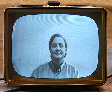
Final Thoughts
Here is the set in operation.
This little TV sat on my computer desk and got regular use for
quite a while. It's an ideal size for a desk or kitchen counter.
I'm proud of this project because it was the first time I
successfully fixed a television that had no hint of a picture
when I started. I certainly learned a lot in the process!
If you
have never worked on a TV before, this model is not a
good project to start on. The chassis is cramped and you must use
care to avoid damaging things when you are moving
the chassis or flipping it over in the course of service.
Given the amount of work involved, it may be a long time before I restore
another one of these little critters. It was gratifying to start out
with a dead $17 flea-market item and end up with a reliable working TV, though.
Why Stop At One?
2009 Update: Despite my vow to leave these sets alone, I ran across another one
at a price I couldn't resist. It's the same black color, but it includes
the metal stand and the rear antenna box is in nice shape. Although I won't get
to this project for a while, perhaps someday this will be my
"keeper" and I'll pass along the first one.


Why Stop At Two?
2010 update: Against my better judgement, I bought a third one. The second set
still hasn't been restored, but this one has a pristine red cabinet and the
price was too good to pass up. I swear I'll stop at three!
|