|

Powering Your Radio Safely With a Dim-bulb Tester


The moment you bring home a "new old" radio or TV, the temptation is to
plug it in and try it out. That's always a bad idea.
For all you know, the set may have a short circuit in the power cord,
failed electrolytic capacitors in the power supply, or
other serious problems not obvious to the naked eye. Turning it on
prematurely may damage expensive parts or even start a fire.
Many experienced restorers replace all the electrolytic capacitors
in a set before attempting to start it up. If your radio is valuable or it has great personal
value, that's the prudent course. Read Replacing Capacitors
in Old Radios and TVs for details.
There are other basic steps, such as inspecting for ruined parts, testing
tubes, and cleaning controls, which should also be performed before power-up.
These are detailed in the article, First
Steps in Restoration. If you haven't already done those steps, please
do them now. It's pointless to turn on a radio that has dead tubes.
What Is a Dim-bulb Tester?
A dim-bulb tester lets you try out a radio or TV under safe conditions and see
whether it has problems in its power supply. You can build one in an evening.
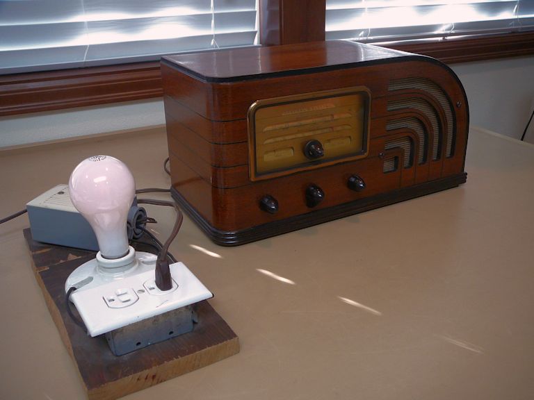
Here's my old dim-bulb tester, which I built about 25 years ago. It's a few spare
electrical parts mounted on a piece of scrap wood, and it includes a power switch,
although the switch is optional.
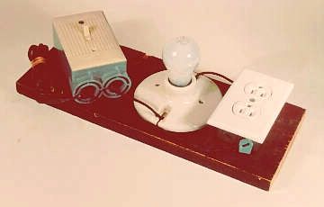
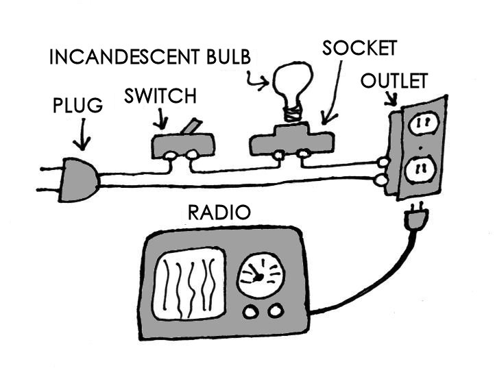
The sketch shows how I wired the tester.

As the diagram shows, the dim-bulb tester puts an incandescent light bulb between
your radio and the AC power in the wall. This way, if your radio has a short circuit, it will
simply light up the bulb instead of damaging itself.
Safety Note: the dim-bulb tester involves
high-voltage current. If you aren't experienced with household wiring,
or this diagram looks confusing, get assistance from someone
more experienced. If you don't know anyone like that, try contacting
an area collector club; you might find someone willing to help.
The ARC website has a list
of clubs in the USA and throughout the world.
Note Your Radio's Wattage!
You must choose an incandescent light bulb of the correct wattage when using this tester (more about the incandescent requirement later).
If your radio is a typical five-tube set, it probably uses about
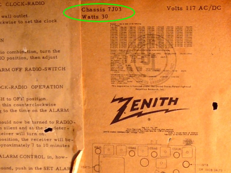
30 to 35 watts of power. The radio's wattage is often stated on a label on the back,
bottom, or inside. For example, here is the label from my Zenith Z-733
clock radio, showing that it consumes 30 watts:
More complicated radios have more tubes and thus draw more power. For example,
my Hallicrafters SX-88 shortwave radio has 20 tubes and it draws 138 watts.
Most vintage TVs draw even more. To use a dim-bulb tester with these, you'll need
to use higher wattage bulbs.
If the bulb's wattage is too low, it will light brightly even if your radio has no
problems, and your radio won't play at all. We'll demonstrate this in an example below.
Your radio should play normally without fully lighting
a bulb that is roughly 1.5 to 2 times the radio's stated wattage.
Using the Tester
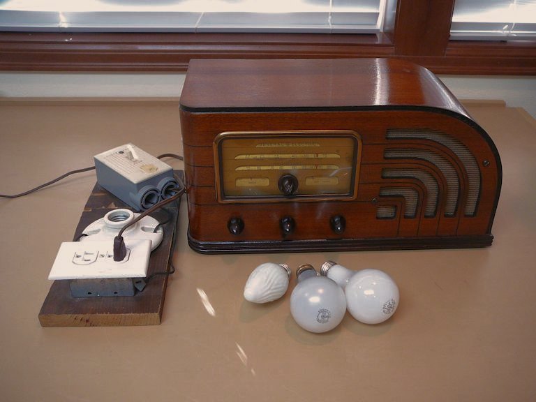
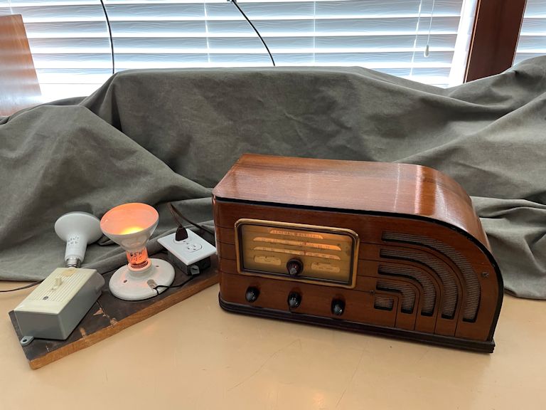
Let's look at a real-world example. The next photo shows my GE F-63.
This radio has been fully restored and it works like new. Next to it are my dim-bulb tester
and three bulbs, of 40, 75, and 150 watts. I have plugged the tester into the wall and
plugged the radio into the tester.
This six-tube GE radio draws 70 watts, according to its label. You would normally use a bulb equal to that or somewhat higher,
but let's see what happens when you put a 40-watt bulb in the tester and try to power the radio:
The 40-watt bulb glows very brightly and the radio doesn't play.
This is not a sign of trouble—the bulb is simply too small, only a little
over half the wattage drawn by the radio. This example shows
that there's no point in using a too-small bulb: it won't tell you anything useful.
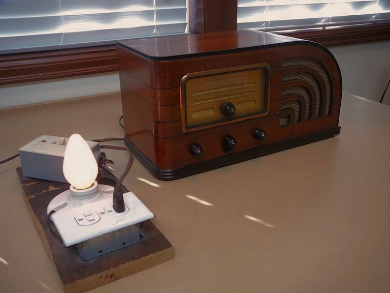
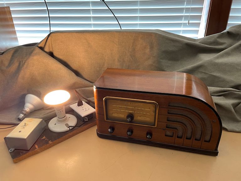
Now, let's substitute a 75-watt bulb, which approximates the radio's 70 watts.
The 75-watt bulb shines dimly—notice the faint pink-orange glow—and the radio plays
normally. It takes a few seconds longer than usual to warm up, and the bulb shines a little more
brightly during that warm-up period. This is normal behavior for a good radio when the wattage
of the bulb is roughly the same as the radio's wattage.
If this 75-watt bulb shone brightly, rather than dimly, that would indicate a problem such as
a short-circuit in the radio. You should not turn on the radio any more until you
investigate the problem.
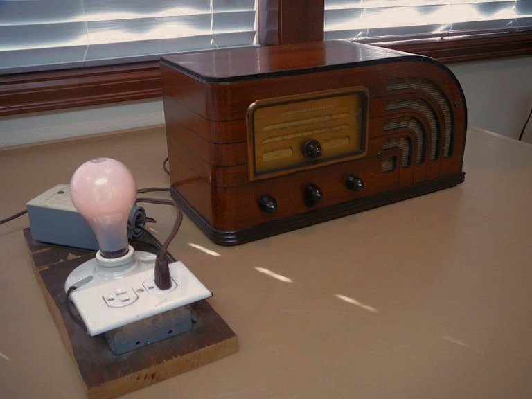
The final example uses a 150-watt bulb, slightly more than twice the radio's wattage.

The 150-watt bulb barely glows at all. The radio warms up quickly and it plays normally.
This is what you'd expect from a normally-functioning radio. If this large
bulb shone brightly, that would flag a problem.
Passing the dim-bulb test doesn't mean that your radio works perfectly, only
that it doesn't have a catastrophic short circuit in the power supply.
There are many other faults that can't be detected by this device. But it does
allow you a safe startup. If the radio contains a short circuit, the current load
is taken by the light bulb rather than your radio, preventing damage to the radio.
Use Incandescent Bulbs, not LED or Fluorescents
To get meaningful results, your tester must use "old fashioned"
incandescent light bulbs.
Do not use modern LED bulbs or fluorescent bulbs, which emit roughly the
same amount of light, but use far less power.
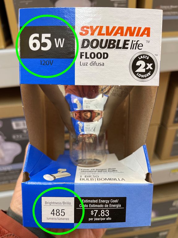
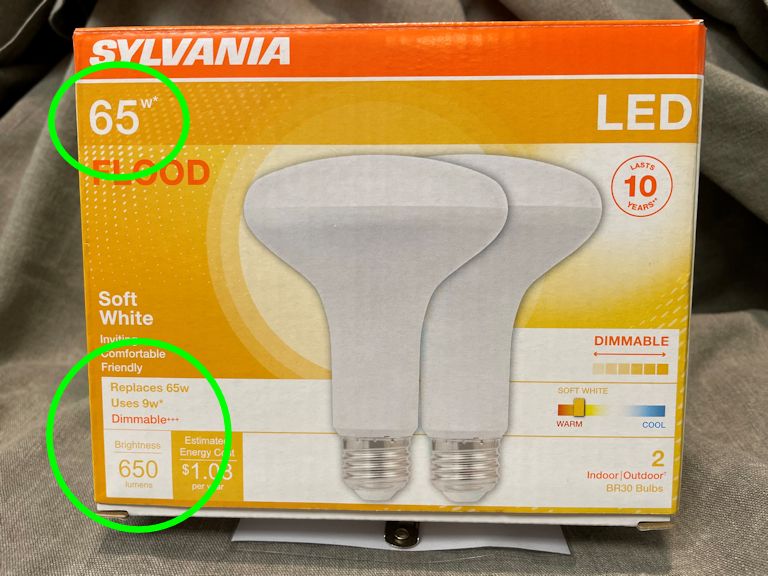
The first photo shows a traditional
incandescent bulb rated for 65 watts. The second shows
a modern LED bulb rated for "65W*," with a footnote stating it
replaces a traditional 65W bulb (in brightness), but it
uses only 9 watts of power.

Conserving energy is great for Mother Earth. But if you use this LED bulb
in a dim-bulb tester, the results will be false because its power consumption
is so low—about the same as a 10-watt night-light bulb.
Let's demonstrate, using the two bulbs pictured above.
First, we'll use the incandescent 65-watt bulb:

Great! The incandescent bulb lights dimly and the radio plays normally. (Notice the radio's
dial lamp is lit up.) That's exactly what we'd expect from a fully restored radio that
draws 70 watts.
Now let's substitute the "65-watt-equivalent" LED bulb:

Wrong! The light shines very brightly and the radio doesn't play at all.
This is a false result, caused because the LED bulb's power rating (in
watts) is too low.
With an incandescent 65-watt bulb, these signs (very bright
illumination, failure to play) might signal a power-supply problem
such as a bad power transformer. But we know this radio has no
such problem. We simply used the wrong type of light bulb.
Again, use only incandescent bulbs in your dim-bulb tester.
Checking the Power Transformer
Here is a handy procedure which I found in an old radio service book. It is used to
check the transformer and input filter capacitor in a transformer-type power supply.
(This will not work with an "AC/DC" type power supply, which lacks a power
transformer. Of the two radios mentioned earlier in this article, the Zenith Z-733
has an AC/DC type power supply and the GE F-63 has a transformer type supply.)
To check the power transformer:
-
Remove all tubes from the radio. Note where each tube belongs, so you can later replace it in the correct socket.
-
Place a 25-watt or 40-watt bulb in the dim-bulb tester and plug the
radio into the tester.
-
A good transformer will cause the lamp to glow dimly after a few moments.
If the lamp glows brightly, you have a short circuit; the transformer should
then be disconnected and checked.
-
If the transformer is OK, put in the rectifier tube, put a 100-watt bulb
in the dim-bulb tester, and try again. If the rectifier tube lights up and
the lamp glows brightly, you
have a short-circuit in the filter capacitor of the power supply.
When you replace the tubes in the radio,
be sure to put them back into the right sockets!
Although this method is quick and convenient, there are other ways to check the transformer and filter capacitors, of course.
Building a Dim-Bulb Tester
There are many ways to build this simple device. One variation would be to use a three-way light socket. Then
you could install a three-way bulb and simply turn the switch to change the bulb's wattage.
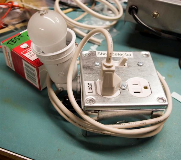
A couple of years ago, Kai Lydestad shared these photos of his dim-bulb tester:

As Kai explained:
I don't have a very large bench, so I made this compact version using
a floodlamp socket designed to fit a hole the size of a conduit punch-out.
The bulb socket, power output, and switch all share a single two-position
junction box. AC input is provided by a cut computer cord running into the
box through a cable relief collar.
I like Kai's compact design. If I didn't already have a dim-bulb tester, I'd
build one like this.
Several years after writing this article, I ran across a commercial tester built by the
Christy Electronics company in Chicago. It serves the same purpose as my simple dim-bulb
tester and it includes additional parts, such an ammeter, making it more versatile. See the
Christy Electronic Tester article for more information.
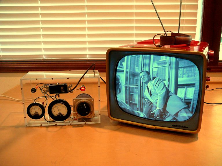
Dim-bulb Tester vs. Variac
In discussions of trying out unrestored radios or TVs, you'll sometimes hear mention
of a variac. A variac isn't equivalent to a dim-bulb tester, but each device has its uses,
when testing a vintage tube device. In this photo, I'm playing
a restored TV using a variac:

In a nutshell, a variac lets you vary the line voltage supplied to your radio or TV.
It's handy for powering a set at a specified voltage (say, 117 volts rather than
the usual 120), or for gradually increasing the line voltage while you try out an unrestored set.
For more details, see my Variacs article.
In contrast, a dim-bulb tester doesn't change the supply voltage. However, by putting a light
bulb in series with your device, it limits the amount of current supplied to your
device, thus reducing the risk of damage if there is a power supply problem, etc.
This radio construction project, including all descriptions, diagrams, photos, and the underlying electronic design, is published here for the noncommercial use of radio hobbyists. You may print and reproduce these project instructions for your personal use. Commercial use of this material is strictly forbidden.
|