|

First Steps in Restoration


This article explains basic preliminary tasks—cleaning and testing—that
are part of every restoration. I do these jobs before I replace any
parts, and usually before I try to power up an old radio or TV.
In my Restoration section, you'll find many articles
about restoring specific radios and TVs. I also explain
replacing capacitors, the major task in every restoration.
Those jobs take place after the first steps described here.
You should not power up an unrestored radio or TV before doing a
basic checkup. That may destroy expensive parts or start a fire, and
it won't tell you anything very useful.
Get the Schematic
The schematic diagram is your roadmap to a vintage radio or TV, identifying
all of the parts and showing the connections among them. My article about
replacing capacitors lists sources for schematics
I strongly recommend that you get the schematic before attempting any work on
your set. A repairman with decades of experience might be able to restore a
radio or TV without a schematic, but not a beginner. Although I have restored
dozens of radios and TVs, I always obtain a schematic and refer to it regularly
during the restoration.
Clean and Inspect the Chassis
Most old radios and TVs require a little cleaning, and some
need a lot. You don't need to make the chassis look brand new before
you begin restoration, but you should at least remove enough grime to
make a reasonable inspection.
Removing the Chassis
Removing the chassis is usually pretty self-explanatory. Before taking the chassis out,
you must remove the knobs and the back cover, if the set has one. You must also
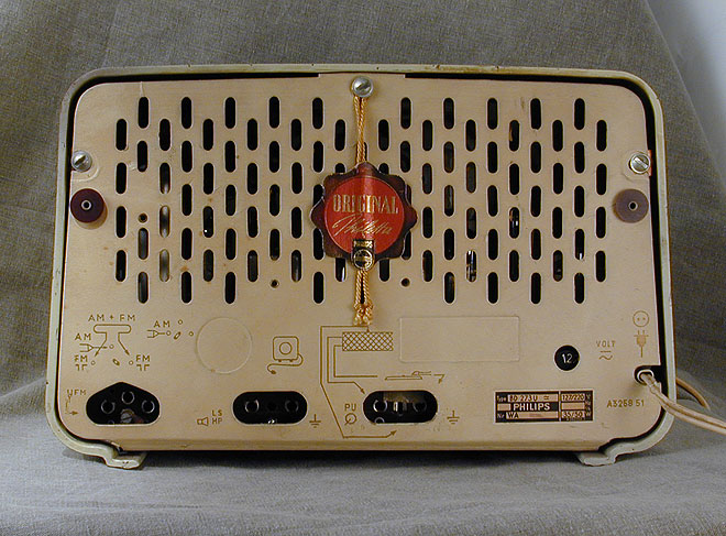
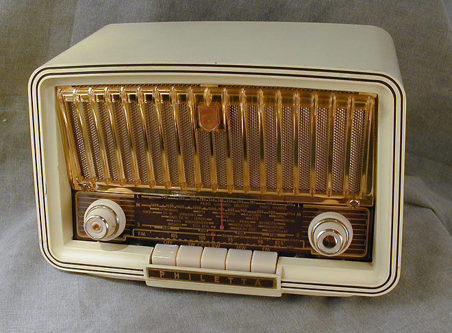
disconnect or remove the speaker. This Philips
Philetta is typical:

Many knobs simply pull off. Others have setscrews that must be loosened before removing the knob.
If a knob is stuck hard on the shaft, heat from a hair dryer may expand it enough to slip off.
You can also protect the cabinet with thin cardboard (try a cereal box) and gently lever off the knob
using a pair of thin blades, alternating from side to side. Another method is to loop a stiff cord
around the shaft behind the knob and pull it outward, again alternating force from side to side.
If rust is an issue, try soaking the shaft overnight with penetrating oil.
Back covers are held on with little screws or T-shaped fasteners that slide out.
Some tabletop radios have a loop antenna mounted on the back cover or the rear of the
chassis. The antenna is connected to the chassis with a couple of wires. Be careful not
to break those wires. Depending on construction, it may be more convenient to remove
the antenna first, or to leave it loosely connected and remove it along with the chassis.
The speaker is usually mounted on the cabinet, or sometimes on the chassis. If it is
mounted on the cabinet, look inside for wires connecting the speaker to the chassis.
These wires will need to be unplugged or unsoldered if you want to leave the speaker
attached to the cabinet. An alternative is to remove the screws holding the speaker
to the cabinet and remove it with the chassis.
The chassis is usually mounted in the cabinet with four bolts from underneath, or occasionally with a couple of bolts from the back.
Remove the mounting bolts and slide the chassis out. Most will come out from the back,
but a few will slide out from the front.
After the chassis is out, I usually replace the knobs on their shafts and screw
the mounting screws back into the holes where they came from, to avoid losing
these parts. If you don't want to do this for some reason, put them in a
ziploc bag and label the bag.
Cleaning the Chassis
Cleaning the chassis is not difficult and it will help you inspect for
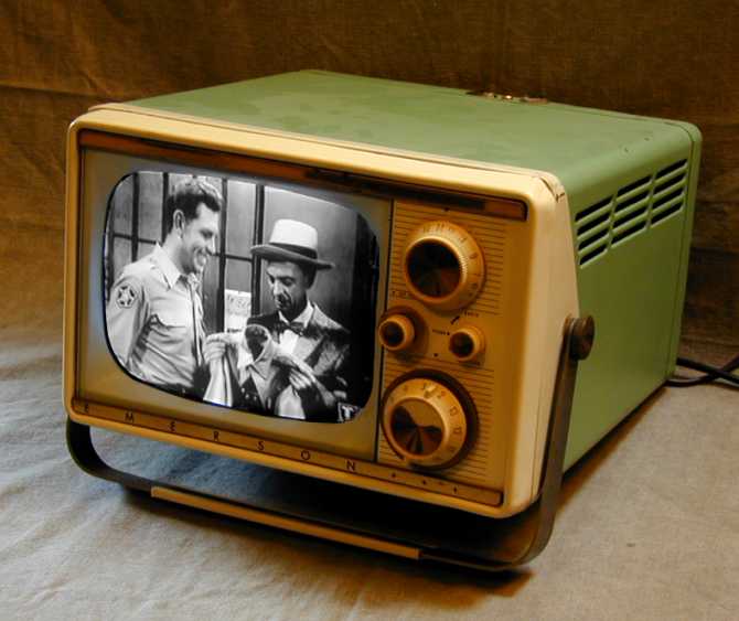
signs of problems to address in your restoration. Here are some before
and after photos of an Emerson model 1232 radio/TV:


Most sets are not this dirty, but this one had been used in a kitchen
and it was coated with a layer of greasy dust. Although ugly to look at,
this kind of gunk cleans up easily, and the grease actually protects against surface rust.
I begin by brushing off dust with a soft brush and blowing it away,
followed by a wipe-down with isopropyl alcohol ("rubbing alcohol") and paper towels.
Alcohol is an excellent cleaner for electronics because it cuts grease and leaves no residue.
Q-tip cotton swabs are handy for getting into corners. You can also use an old
toothbrush or even a small folded square of non-scratch household cleaning pad held in a
needle nose pliers or large tweezers.
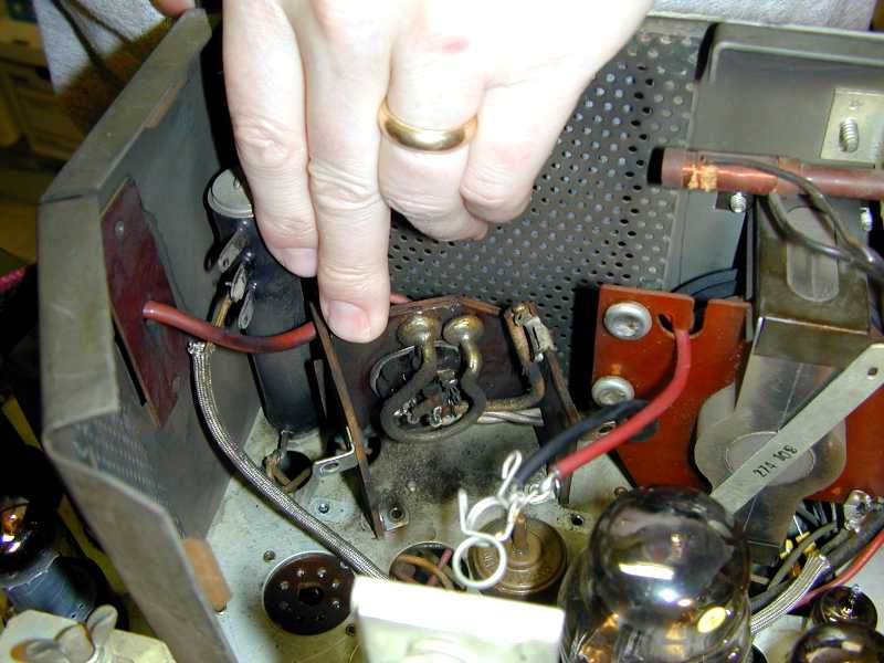
The high voltage compartment of a television deserves special attention, since dirt in there
can lead to destructive arcing. In some TVs, the high-voltage
rectifier tube is mounted on a little platform, which can be lifted up for cleaning.

Again, alcohol works well for cleaning the entire compartment.
At this early stage, my goal is to make the chassis
presentable, not a mirror-bright museum piece.
Some people spray a dirty chassis with a garden hose and then let it bake
in the hot sun or a low oven. I don't advocate this method. Components such
as coils, IF transformers, and tuning capacitors were not designed to be submerged in water.
After I finish restoring the electronics, then I'll decide whether
further cleaning is needed.
Managing the Chassis on the Workbench
A small chassis can often be laid sideways on your workbench to access the
underside. If it doesn't stand
securely on its own, a board or piece of styrofoam packing material may help
steady it.
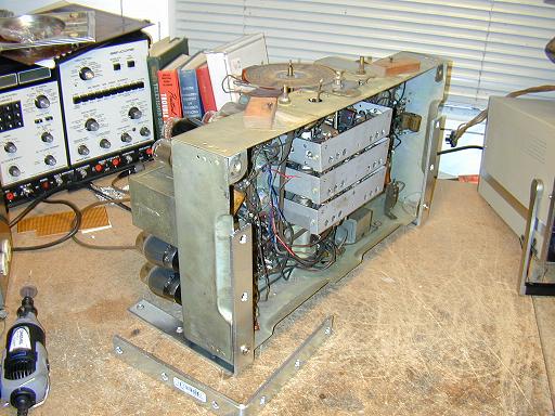
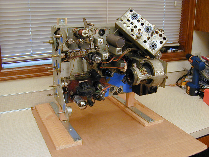
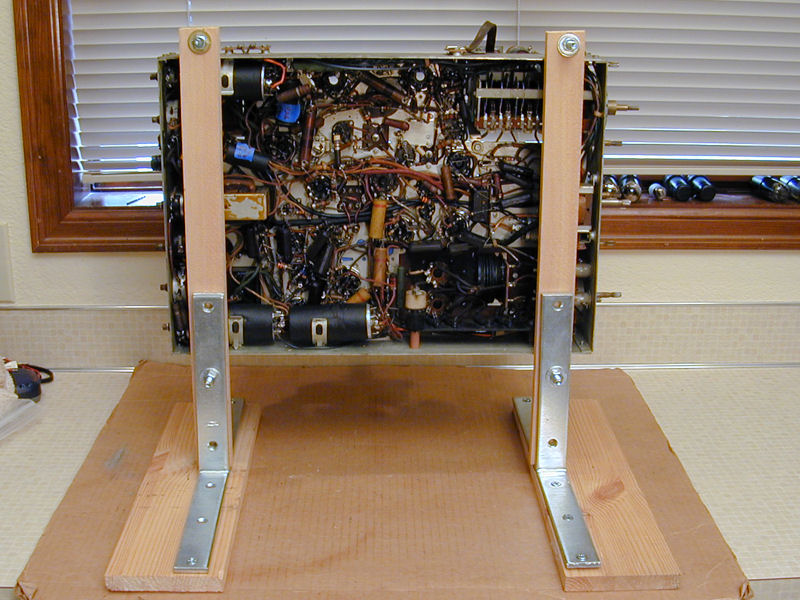
A large radio or television chassis may need more support. For very heavy chassis, I use
stout "L" braces to form an inexpensive chassis holder.

Screwing the braces into a couple of boards makes a heavy-duty
chassis stand with feet:


Inspecting for Obvious Problems
Although the internal condition of most electronic parts is hidden, you should
look under the chassis for obvious problems, such as missing parts, disconnected wires,
and burned or broken components.
Cracked or broken power cords are very common. If your power cord has either problem,
replace it before you try to power up the set.
If a resistor or capacitor suffers catastrophic failure, then it may crack, break in
half, or blow its end out. These obviously ruined parts must be replaced, of course.
If a component looks OK on the outside, then it might or might not be good.
Quick eyeballing can't identify parts that have failed internally, and most of
the electronic restorer's time is spent replacing parts that look fine
to the casual eye.
Paper capacitors are a good example. It's common to see melted wax on them,
primarily resulting from the heat of normal operation. The appearance of the wax
tells you nothing about the capacitor's internal condition. It can look melted
yet still be usable. Conversely, it might look perfect on the outside yet leak
electronically and be useless. The leakage is caused by water vapor that invisibly
penetrates the capacitor over time, damaging the interior.
If you notice an obviously ruined component, note its location and plan to replace
it later, when you will be spending a lot of time replacing capacitors.
(It does no harm to replace it now, but your set will probably not spring to life
merely from that action, since it will still be full of defective old capacitors.)
In a small number of old radios, the insulation on the wires under the chassis
degrades over time and becomes brittle, falling off in pieces. If your radio has
only one or two wires like this, it's easily cured by unsoldering one end of the
wire and slipping new insulation over it.
Replacing all of the wires in a set is an extreme measure, which I have never
needed to do in the course of restoring several dozen vintage radios and TVs.
If your set has suffered mass loss of insulation underneath, then reinsulating
the wiring is necessary. But removing and replacing every wire is an
invitation to make many wiring mistakes. Furthermore, in some circuits the
original "lead dress," or precise routing and length of
wires, may be critical. Rewiring your set willy-nilly
may cause it to work poorly, even if you don't make any obvious connection errors.
Clean and Test the Tubes
Every tube in your radio or TV should be removed for cleaning and testing. This elementary step
should be done sooner rather than later. Playing a radio or TV with untested
tubes is like finding a 50-year old car in a barn and trying to start it without
checking the gas gauge.
Novices sometimes replace every tube in an old set, but that's a foolish waste of money. Tubes
are vacuum sealed and they don't deteriorate from merely sitting around. Most of the time,
most of your tubes will still be usable, and replacing them with new ones
won't improve performance at all.
Clean and test one tube at a time to avoid mixing them up. At the same time, compare the
tube's type to the diagram given in your schematic diagram or in the label pasted
to the cabinet. Occasionally, you'll find that a previous owner mixed up
two tubes or simply plugged a random tube into an empty socket to fill it up.
After removing the tube, wipe off dust with a dry paper towel and write down its
type number (45, 12AT7, 50C5, whatever). The markings on some tubes may be
faint. Avoid harsh cleansers or too much scrubbing, which can erase all of the
tube's marking. Don't worry about making the tube look brand new at this stage.
If it's a dud, there's no point wasting time on it.
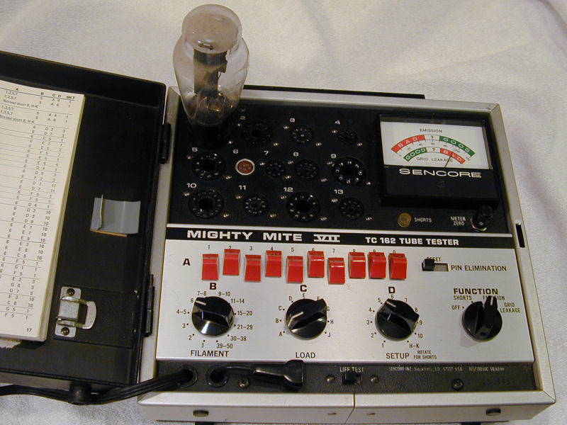
If you have a tube tester, pop in the tube and check it out. In this photo, I am
testing a rectifier tube with my trusty Sencore "Mighty Mite" tester.
If the tube is shorted
or has no emission, then it needs replacement. If it tests as "weak," don't
throw it out yet. In many cases, a so-called weak tube will work well enough
to let you proceed with the restoration.
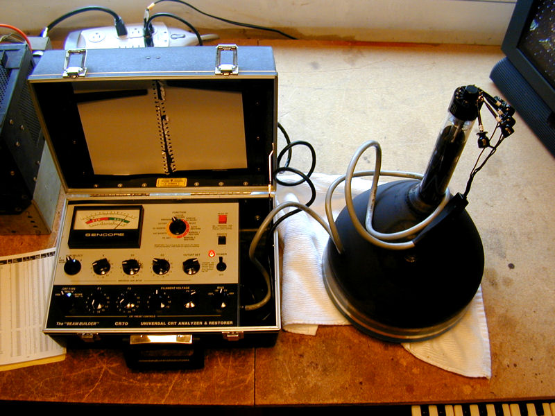
TV picture tubes are a bit of a special case. If the tube immediately shows
strong emission, then it's clearly good. In this photo, my Sencore CR70
tester gives the 10BP4 CRT a passing grade.

If a picture tube looks weak at first, don't write it off. Often,
a CRT that has been unused for a long time will initially show
low emission but perk up after a while. Try leaving it on the tester for a
few hours at normal or even slightly elevated filament voltage. As often
as not, the tube will perform much better after a little "cooking."
Checking Tubes Without a Tester
If you don't have a tube tester, you can still check the tube's filament (heater)
for continuity using an ohmmeter. This allows you to weed out the obvious duds.
A tube diagram will tell you which of the tube's pins connect internally to its filament.
If you don't have the schematic giving this information, you can look up the tube
online at Nostalgia Air or
Frank's Tube Data.
Let's look at the basing diagram for a 6SK7 tube. Next to the diagram is the tube itself:
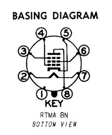
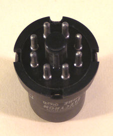
In schematics and tube diagrams, the tube pins are numbered clockwise as if you are looking at
the tube from its bottom. Numbering starts at the key (or gap between pins) in the tube's base.
The filament usually appears at the bottom of the diagram and its symbol is a
peaked chevron. In this diagram, the filament is connected between tube pins 2 and 7.
To test the filament of a 6SK7, put your ohmmeter probes on pins 2 and 7 and note the result.
If your ohmmeter shows infinite resistance, then the filament has
burned up and the tube is a dud. Order a replacement
(see our Parts page.)
If the meter shows continuity—usually a few ohms—then the filament
is intact and the tube should at least light up when powered.
This simple dead-or-alive
test can't measure a tube's emission, of course. The tube could
still be too weak for good performance, but it may be usable during restoration,
and if you're lucky, it's as strong as a new one.
Cleaning Tube Pins and Sockets
If your tube passes the dud test, clean its pins. Use very fine sandpaper to remove
corrosion from each pin and brighten it up. You don't need to go nuts with this; simply
make it clean enough for good electrical contact.
Now is also a good time to straighten any bent pins on all-glass miniature tubes.
A needle nose plier works well. Sometimes, you can simply push the pin back into
line with your finger.
It's also prudent to clean the holes in the tube socket.
Spritz a tiny amount of DeOxit electronic cleaner into
the socket holes and then plug and unplug the tube several times. Remove the
tube and wipe up excess cleaner with a paper towel. Blow out the socket holes with
compressed air or a plastic straw. Electronic cleaners can be conductive when
liquid, so make sure the cleaner has evaporated before you turn the set back on.
For a troublesome socket, I use DeOxit with a tiny
stainless steel brush,
available from CAIG Laboratories.
Clean the Controls and Switches
Next, clean all the set's controls and switches using DeOxit or an equivalent electronic
cleaner. These include volume controls, tone controls, band switches, and so on.
Cleaning eliminates common problems such as a scratchy sound when turning the volume
control, or failure to receive on some bands of a multi-band radio due to oxidized band switch contacts.
Cleaning Band Switches and Tuners
If your radio receives more than one band (for example, shortwave plus the standard broadcast
band), cleaning the band switch is essential. It is
common for grungy contacts to completely prevent reception on one or more bands.
Often, the radio sat unused for years, during which time it was switched to one band.
That band's switch contacts were somewhat protected, but the others were exposed to
dirt and oxidation. Removing the grunge may instantly bring those silent bands back to life.
Depending on the number of bands, your band switch may be simple or complex.
It's often a rotary wafer-type switch with multiple wafers. The next photo shows
a rather complex switch from my six-band Midwest DD-18
console:

In this view, the front of the chassis faces upward and the knob would be mounted
at the top. The band switch wafers are mounted on a long shaft that runs down
through three compartments.
Apply DeOxit sparingly to the contacts on each wafer and then switch the control through every
band several times.
Avoid spraying cleaner everywhere. It's a good idea to avoid soaking
the phenolic wafers with too much cleaner. A better method is to apply DeOxit with a wetted
Q-tip. However you apply it, clean up any excess and let everything dry before
powering the set back up.
Avoid rubbing switch contacts with anything abrasive. Some contacts are plated with
an extremely thin layer of precious metal. If you scrape off that layer, the switch
may work poorly or fail completely after a while.
Beginners are sometimes tempted to polish a switch's contacts with a Dremel Moto-Tool
or similar device so that everything looks shiny and brand new. This is unnecessary and
it can be very destructive. You want the switch parts to make good electrical
contact, not win a beauty contest. Save the power tools for polishing the chrome
bumper on your car.
Television tuners are another type of band switch and they also benefit from cleaning.
You can read about this more specialized topic in the articles about my
RCA CTC-11H (wafer tuner) and
Philco 49-1240 (turret tuner).
Cleaning Potentiometers
Your volume control is a potentiometer (variable resistor). Inside the case is a metal
wiper that moves along a curved resistive strip. Dirt on the wiper or strip can make
the potentiometer work poorly.
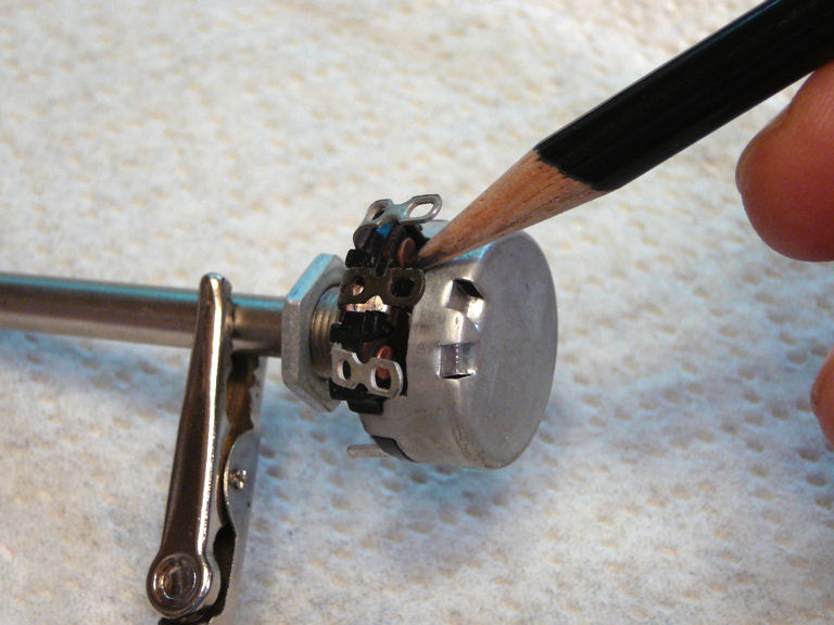
Many potentiometers have a small slot in the case below the three solder terminals.
This photo shows a pot of that type:
This new potentiometer had never been installed. In your radio, of course, the shaft
will be fastened to the chassis and wires will be soldered to the terminals. Often,
the slot will be exposed and you can clean the pot without removing it from
the chassis. In other cases, you can loosen the mounting nut and rotate the pot
enough to reach the opening with the cleaner nozzle.
Cleaning takes only a few seconds. Spritz a tiny amount of cleaner into the control and
then rotate the pot all the way back and forth a number of times. Blot up excess cleaner
with a paper towel and allow the cleaner to evaporate from inside the control before
turning the set back on.
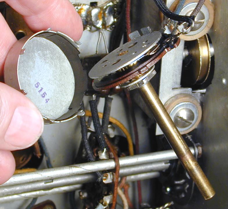
Some potentiometers have a sealed case. These can be cleaned after disassembly.
Bending up the thin metal tabs around the case allows you to slide out the control mechanism:

Sometimes, the connecting wires have enough slack that you can clean this type of pot without
unsoldering them. In the next photo, I have removed the case from the tone control in my
Zenith 12-A-58, leaving it connected by its wires.

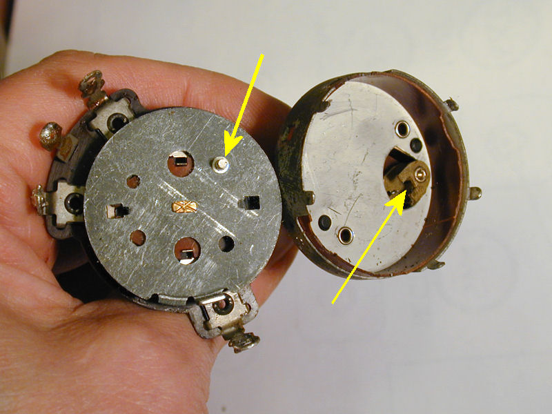
Pay attention to the control mechanism's orientation in the case so that you can reassemble
it the same way. A volume control will often have a power switch attached to its back.
The next photo shows a control from my
Stewart Warner 1865 console. The arrows point to
the little pin and cam for the power switch. These must be correctly engaged when
you reassemble the control.

Inside every potentiometer, you'll find a metal wiper that travels around a
resistive strip. Clean both parts with DeOxit and work the control back and forth.
After reassembling it, bend the metal tabs back down.
Occasionally, an old control grows "dendrites" internally or on its case. The next photo shows dendrites in the volume control of my Stewart Warner 1865.

Dendrites are easy to clean off, and if you do a thorough job it may be years before
they return, if ever. You can read
more about them in my Stewart Warner 1865 article.
Dendrites and "tin whiskers" can even form on the outside of a control, causing
a short circuit to the chassis. Normal cleaning under the chassis usually clears them up.
This is yet another reason to clean every chassis thoroughly!
A third type of potentiometer, the "wirewound," contains a curved coil of
resistive wire rather than a resistive strip. Most radios don't use this type, but you'll occasionally find one in a high-current application such as a television focus control. In
a parts list or schematic, it will be designated as wirewound, sometimes abbreviated WW.
This type of pot typically doesn't need cleaning—it either works or it doesn't—so
you can ignore it for the time being.
Test Other Components
This section will be short because, in many restorations, I don't test anything
except tubes before beginning to replace capacitors.
Many components such as coils and transformers are so reliable that testing
at this stage is premature.
Paper and electrolytic capacitors fall in the opposite category. Those types are so
unreliable that testing is also a waste of time. If 99.9% of them are defective,
why test? This is not true of all capacitors, only certain types. My
recapping article explains in detail
how to identify the different kinds of caps and tell which ones to replace.
Resistors fall somewhere in between. More reliable than the worst types of capacitors,
they still can change value with age, usually drifting upward to a higher value.
Often, however, the precise value of the resistor wasn't that critical in
the first place, and so your radio or TV will work the same even if, say,
a 39K resistor has drifted to 46K.
My usual practice is to replace capacitors first
and then see how well the set works. If it still has problems after recapping,
and it will often have a few minor issues, those will be easier to identify
and fix after I establish a baseline of performance.
Occasionally, inspection will reveal a reason to test a particular part.
For example, if I see a large amount of melted wax under a TV's flyback
transformer, I will check the resistance of the transformer windings to
rule out an obvious short or open circuit.
Order New Parts
My Parts page lists popular sources for capacitors, resistors,
schematics, and restoration supplies.
Serious restorers keep a stock of commonly-used capacitors and resistors on hand,
so they can immediately start work after completing the initial cleanup and
testing. I try to keep my shop well supplied, but it's a rare project
when I don't end up ordering some doo-dad or another.
What's Next?
You needn't be idle while waiting for parts to arrive in the mail.
Now is an ideal time to work on your radio or TV's cosmetics. Clean those
grubby knobs, polish that dial cover, refinish the cabinet if that's
in the cards.
As soon as you have the needed parts, you can replace
capacitors. I always start with the electrolytic capacitors in the
power supply, since the rest of the set can't possibly work if those are defective.
Once the power supply is healthy, you can cautiously power up your set,
using a metered variac if you have one, or a dim-bulb tester
if you don't.
After that, you're off to the races. Have fun!
Phil Nelson
|